roll HONDA INTEGRA 1994 4.G Owner's Manual
[x] Cancel search | Manufacturer: HONDA, Model Year: 1994, Model line: INTEGRA, Model: HONDA INTEGRA 1994 4.GPages: 1413, PDF Size: 37.94 MB
Page 491 of 1413
Transmission
Removal
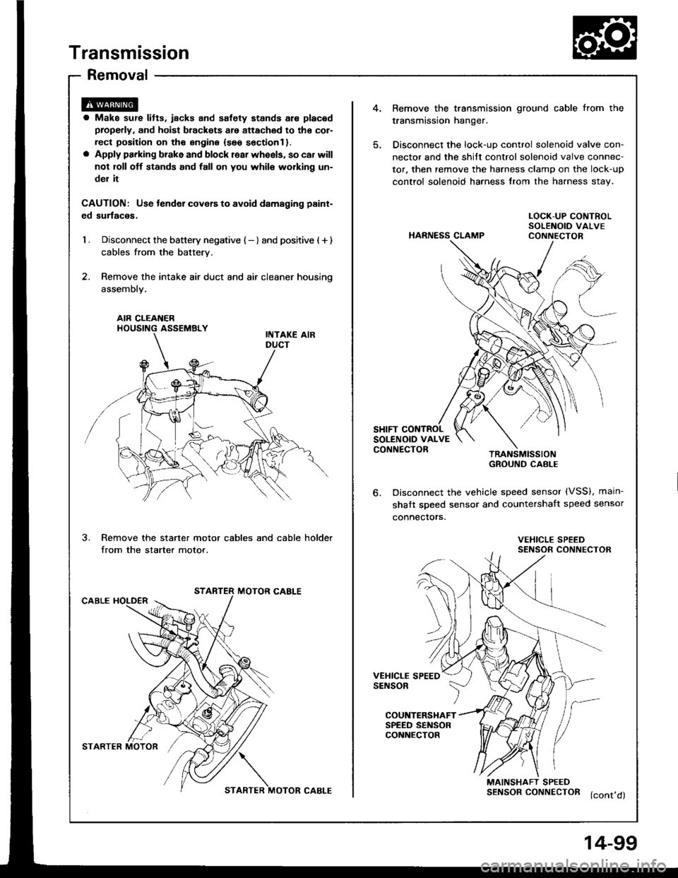
4.Bemove the t.ansmission ground cable from the
transmission hanger.
Disconnect the lock-uD control solenoid valve con-
nector and the shitt control solenoid valve connec-
tor, then remove the harness clamp on the lock-up
control solenoid harness from the harness stav.
a Make sur€ lifts. iacks and safety stands are placad
properly, and hoist brackots are attachod to tho cor-
rect position on ths sngine {seo sectionl }.o Apply parking brake and block rear wheels, so car will
not roll off stands and fall on you whil6 working un-
del it
CAUTION: Use tender covers to avoid damsging paint-
ed surlaces,
1 . Disconnect the battery negative { - } and positive ( + )
cables from the battery.
2. Remove the intake air duct and air cleaner housino
assembly.
HARNESS CLAMP
LOCK-UP CONTROLSOLENOID VALVECONNECTOR
AIR CLEAI{ERHOUSING ASSEMBLY
SHIFT CONTROLSOLENOID VALVECONNECTORTRANSMISSIONGROUND CABI-E
Disconnect the vehicle speed sensor (VSS), main-
shaft sDeed sensor and countershaft speed sensor
connectors.
3.Remove the starter motor cables and cable holder
from the starter motor.VEHICLE SPEEDSENSOR CONNECTOR
STARTER MOTOR CABLECABLE HOLDER
VEHICLE SPEEDSENSOR
COUNTERSHAFTSPEED SENSORCONNECTOR
MAINSHAFT SPEEDSENSORCONNECTOR (cont,d)
STARTER MOTOR?/\
STARTER MOTOR CABLE
4-99
Page 493 of 1413
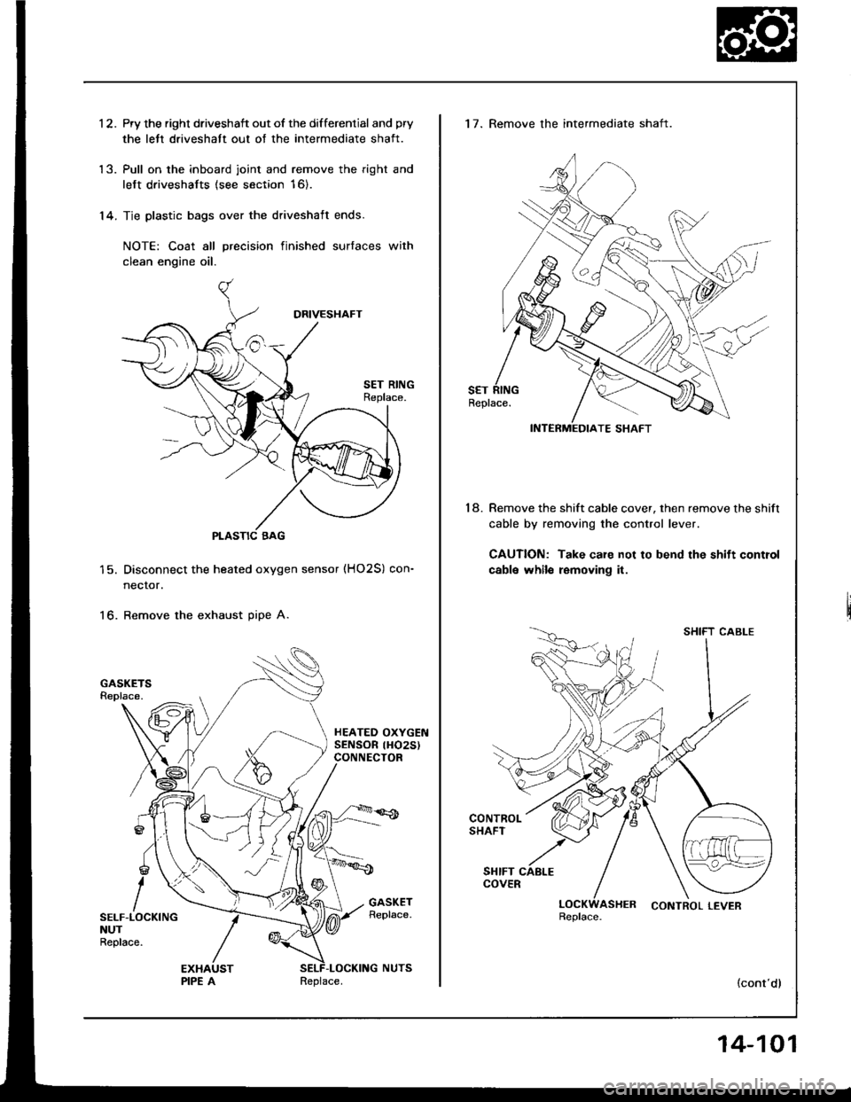
1 2. Pry the right driveshaft out of the differential and pry
the lett driveshatt out of the intermediate shaft.
'13. Pull on the inboard joint and remove the right and
left driveshafts (see section 16).
'14. Tie plastic bags over the driveshaft ends.
NOTE: Coat all precision finished surfaces with
clean engine oil.
PLASTIC BAG
Disconnect the heated oxygen sensor (HO2S) con-
necror.
Remove the exhaust pipe A.16.
SELF-LOCKINGNUTReplace.
Replace.
14-101
17. Remove the intermediate shaft.
Remove the shift cable cover, then remove the shift
cable by removing the control lever.
CAUTION: Take care not to bend the shift control
cabls whilo removing it.
18.
SHIFT CABLE
LOCKWASHER CONTROLLEVERReplace.
(cont'dl
Page 496 of 1413
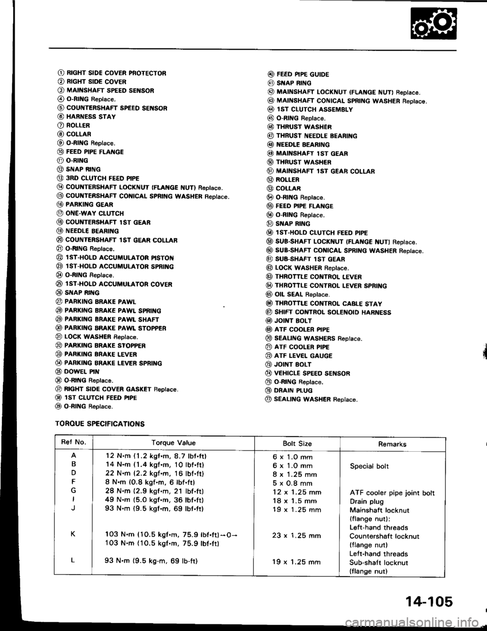
O RtcHT slDE covER pRoTEcToR
@ RrcHT stDE covER
O MAtt{sHAFr spEED sENsoR
@ o-RtNG Reptace.
@ cour{TERSHAFT SPEEO SENSOR
@ HARNESS STAY
O RoLLCR
@ COLLAR
O O-RING Reptace.
@ FEED PIPE FLAI{GE
@ o-RrNG
@ sIrlAP RING
@ 3RD CIUTCH FEED PIPE
@ COUNTERSHAFT LOCKNUT (FLAt{cE f{UTl Reptace.
@ coultTERsHAFf col{tCAL SpRtt{c WASHER Reotace.
@ PARKI G GEAR
@ oNE-waY cLUTcH
@ couNTERsHAFr lsr GEAR
@ NEEDLE BEARING
@ couNTERsHAFr tsr GEAR coLLAB
@ O-RING Reptace.
@ l sT-HoLD accuMuLAToR ptsToN
@ isT-HoLD ACCUMULAToR spBfi{c
@ o-RtNG Reptace.
@ rsT-HoLD ACGUMULAToR covER
@ SNAP Rrr{G
@ PAFKING BRAKE PAWL
@ PARKING BRAKE PAWL SPRII{G
@ PARKING BRAKE PAWL SHAFT
@ PARKING aRAKE PAWL SToPPER
@ LOCK wasHEn Reptace.
@ PARKI G BRAKE s?oPPER
@ PARKING BRAI(E LEVER
@ PARKI G BRAKE LEVER SPBING
@ DowEL PrN
@ O-RltIG Reptace.
@ RTGHT stoE covER GASKET Feptace.
@ isT ct-uTcH FEED ptpE
@ o-RtNG Reptace.
TOROUE SPECIFICATIONS
@ FEED PIPE GUIDE
@ SNAP RING
@ MAINSHAFT LocKNUT {FLANGE NUT) ReDIace.
@ MAfISHAFT CONTCAL SpRtNG WASHER Reotsce.
@ IsT cLUTcH ASSEMBLY
@ O-RING Reptace.
@ THRUST WASHER
@ THRUSI NEEDLE BEARI G
@ EEDLE BEARING
@ MAI'{SHAFT lsT GEAR
@ THRUST WASHER
@ MAINSHAFT lsT GEAR coLLAR
@ RoLLER
@ coLLAR
@ O-Rlt{c Reptace.
@ FEEo PIPE FLANGE
@ o-RING R€ptace.
@ SNAP RING
@ lsr-HoLD cLUTcH FEED ptpE
@ SUB-SHAFT LoCKNUT IFLAt{c€ NUTI Reptace.
@ suB-sHAFr cot{tcAl spRtNG WASHER Reptace.
@ SU8-SHAFT lST GEAR
@ LOCK WASHER f,eptace.
@ THRoTILE cor{TRoL LEVER
@ THRoTTLE coNTRoL I.EVER SPRING
@ oll sEAt Reptace.
@ THRoTTI"E coNTRoL CABLE STAY
@ sHtFT CONTROL SOLEI{O|O HARNESS
@ Jor T BoLT
@ ATF COOLER PIPE
@ SEAL|NG WASHERS Roptace.
@ ATF cooLER P|PE
@ ATF LEVEL GAUGE
@ JOINT EOLT
@ vEHtcLE spEED sEf{soR
@ o-RtNG Reptace.
@ DRAIN PLUG
@ SEALING WASHER Replace.
Ret No.Torque ValueBolt SizeRemarks
B
D
F
K
L
'12 N.m (1 .2 kgf .m, 8.7 lbJ.tt)
14 N.m (1.4 kgf.m, 10lbf.ft)
22 N.m 12.2 kgf.m, 16 lbf.ft)
8 N.m (O.8 kgf.m, 6 lbf.ftl
28 N'm (2.9 kgf .m, 21 lbf.ttl
49 N.m (5.O kgf.m, 36 lbf'ft)
93 N.m {9.5 kgf.m, 69 lbt.ft}
103 N.m {1O.5 kgf.m, 75.9 lbf.ftl-O-
1O3 N.m (10.5 kgf'm. 75.9 lbf.ft)
93 N.m (9.5 kg-m, 69 lb-ft)
6 x 1,O mm
6 x 1.O mm
I x 1.25 mm
5x0.8mm
12 x 1-25 mm
18 x '1.5 mm
tY x t.z5 mm
23 x 1.25 mm
'19 x 1.25 mm
Specialbolt
ATF cooler pipe joint bolt
Drain plug
Mainshaft locknut(flange nut):
Left-hand threads
Countershaft locknut(tlange nut)
Lett-hand threads
Sub-shatt locknut(flange nut)
14-105
Page 508 of 1413
Valve Body
Repair
NOTE: This repair is only necessary il one or more of
the valves in a valve body do not slide smoothly in their
bores. You may use this procedure to lree the valves in
the valve bodies.
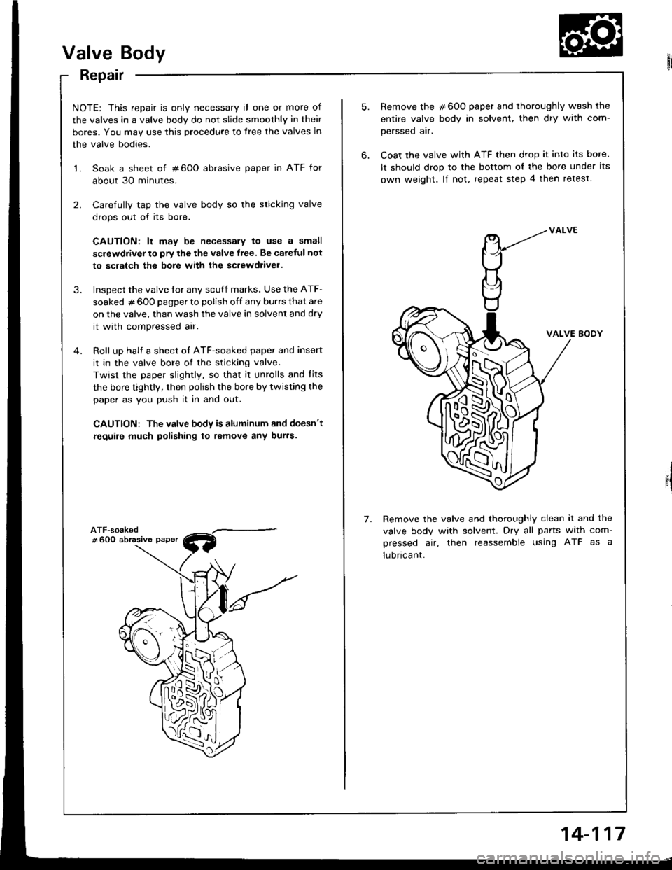
1. Soak a sheet of #600 abrasive paper in ATF for
about 30 minutes.
2. Carefully tap the valve body so the sticking valve
drops out of its bore.
CAUTION: lt may be necessary to use a small
screwdiiver to pry the the valve lree. Be carelul not
to sclatch the bore with ihe sc.ewdliver.
3. Inspect the valve tor any scuff marks. Use the ATF-
soaked # 600 pagper to polish off any burrs that are
on the valve, than wash the valve in solvent and dry
it with compressed air.
4. Roll up halt a sheet oI ATF-soaked paper and insert
it in the valve bore of the sticking valve.
Twist the paper slightly, so that it unrolls and fits
the bore tightly, then polish the bore by twisting the
paper as you push it in and out.
CAUTION: The valve body is aluminum and doesn't
require much polishing to remove any burs.
W
5.
6.
7.
Remove the #600 paper and thoroughly wash the
entire valve body in solvent, then dry with com-
perssed air.
Coat the valve with ATF then drop it into its bore.
It should drop to the bottom o{ the bore under its
own weight. lf not. repeat step 4 then retest.
VALVE BODY
Remove the valve and thoroughly clean it and the
valve body with solvent. Dry all parts with com
pressed air, then reassemble using ATF as a
lubricant.
14-117
Page 509 of 1413
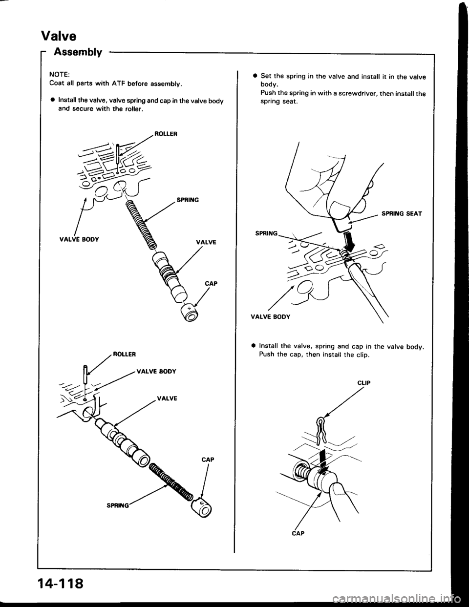
Valve
Assembly
NOTE:
Coat all parts with ATF belore assemblv.
a Install the valve, valve spring and cap in the valve bodyand secure with the 10116r.
ROLLER
VALVE BODY
ROLLER
VALVE EODY
VALVE
5-1-6^<
CAP
14-118
a Set the spring in the valve and install it in the valvebody.
Push the spring in with a screwdriver, then installthespring seat.
SPBING SEAT
VALVE BODY
Install the valve, spring and cap in the valve bodv.Push the cap, then install the cliD,
Page 513 of 1413
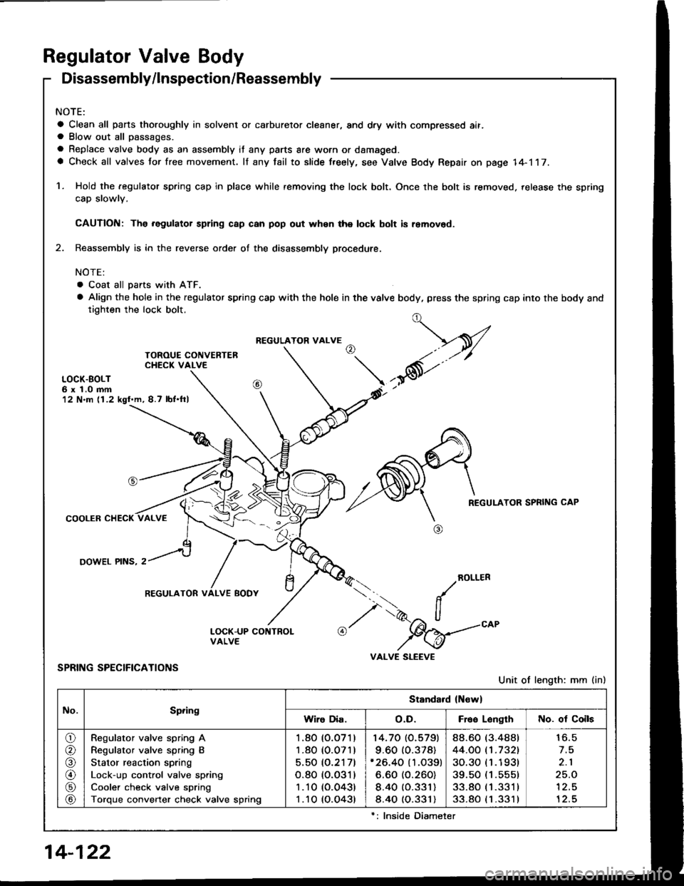
Regulator Valve Body
Disassembly/lnspection/Reassembly
NOTE:
a Clean all pans thoroughly in solvent or carburetor cleaner, and dry with compressed ait.a Blow out all passages.
a Replace valve body as an assembly it any parts are worn or damaged.a Check all valves for free movement. lf any fail to slide freely, see Valve Body Repair on page 14-117.
1. Hold the .egulator spring cap in place while removing the lock bolt. Once the bolt is removed. release the spring
cap slowlv.
CAUTION: The .egulator spring c8p can pop out whsn the lock bolt is removod.
2. Reassembly is in the reverse order of the disassembly procedute.
NOTE:
. Coat all pans with ATF.
a Align the hole in the regulator spring cap with the hole in the valve body, press the spring cap into the body andtighten the lock bolt.
LOCK.BOLT6 x 1.0 mm12 N.m (1.2 kgl.m, 8.7 lbf.ftl
REGULATOR SPRING CAP
COOLER CHECK
OOWEL PINS, 2
ROLLER
SPRING SPECIFICATIONS
Unit of length: mm (in)
../
I',.-2" ll"%=
VALVE SLEEVE
t,-V
,*6t'"
REGULATOR VALVE
REGULATOR VALVE BODY
No.Spring
Standard (New)
Wiro Dia.o.D.Free LonglhNo. of Coils
o/a
@
\9/
Regulator valve spring A
Regulator valve spring B
Stator reaction spring
Lock-up control valve spring
Cooler check valve spring
Torque converter check valve spring
1.80 (O.O71)
1.80 (0.071)
5.50 (O.2171
o.80 (o.o31)
1 .10 (0.043)
1 .10 (O.O43t
14.70 (O.5791
9.60 (0.378)'26.40 (1.O39)
6.60 (O.260)
8.40 (O.331)
8.40 (0.331)
88.60 (3.488t
44.OO t't.7321
30.30 (1 .1 93t
39.50 (1.555)
33.80 (1 .331 I
33.80 (1 .331 )
16.5
2.1
25.O'l2.5
12.5
14-122
lnside Diameter
Page 520 of 1413
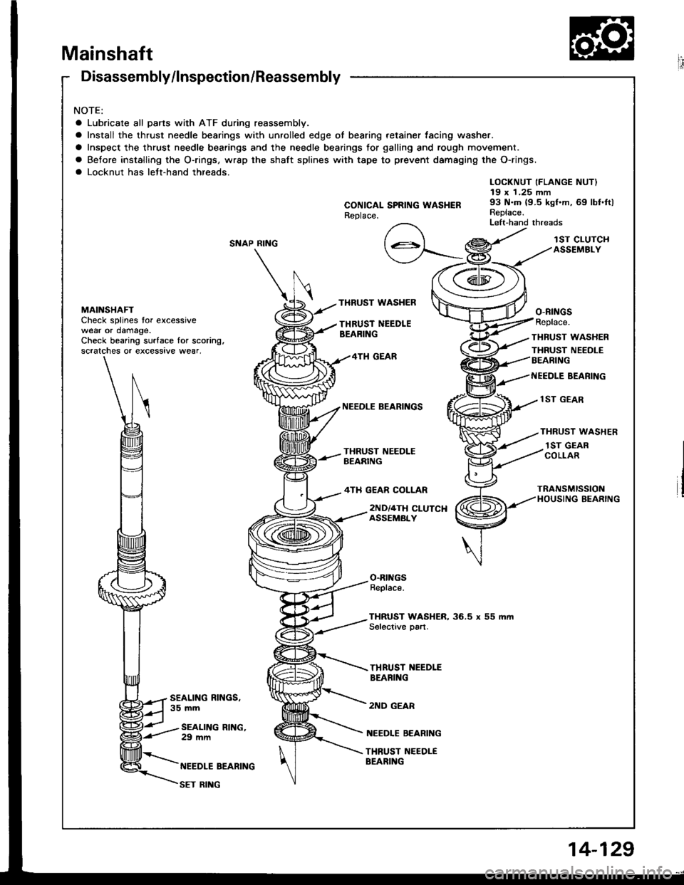
Mainshaft
Disassembly/lnspection/Reassembly
NOTE:
a Lubricate all pans with ATF during reassembly.
a Install the thrust needle bearings with unrolled edge of bearing retainer lacing washer.
a Inspect the thrust needle bearings and the needle bearings for galling and rough movement.
a Betore installing the O-rings, wrap the shaft splines with tape to prevent damaging the O-rings.
a Locknut has lett-hand threads.
RING
\
MAINSHAFTCheck splines tor excessivewear or damage.Check bearing surface for scoring,scralches or excessive wear,
CONICAL SPRING WASI{ERReplace.
LOCKNUT (FLANGE NUT)19 x 1.25 mm93 N.m {9.5 kgf.m, 69 lbf.ftlReplace.Left-hand threads
SNAP
THRUST WASHER
THRUST NEEDLEBEARING
lST CLUTCHASSEMBLY
o-ntNGsReplace.
THRUST WASHER
THRUST NEEDLEBEARING4TH GEAR
NEEOLE BEARIT{GS
4TH GEAR COLLAR
lST GEAR
THRUST WASHER
BEANING
1ST GEARCOLLAR
TRANSMISSIONHOUSING BEARING
SEALING RINGS,35 mm
2ND/4TH CLUTCHASSEMBLY
NEEDLE BEARING
THRUST NEEDLEBEARING
O.RINGSReplace.
THRUST WASHER, 36.5 x 55 mmSolective part.
THRUST NEEDLEBEAFING
2ND GEAR
SEALING RING.29 mm
NEEDLE BEARING
SET RII{G
Page 523 of 1413
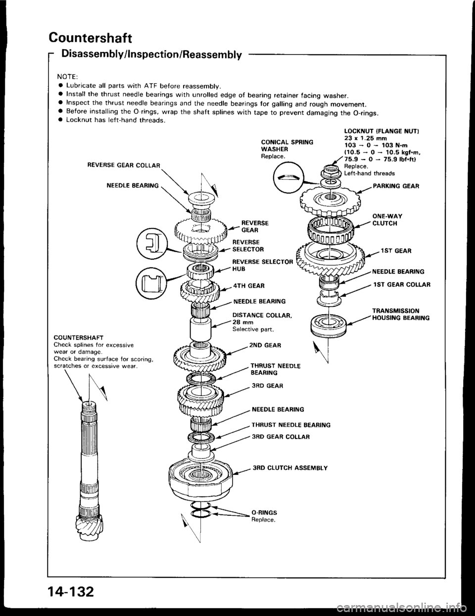
Countershaft
Disassembly/lnspection/Reassembly
NOTE:
a Lubricate all parts with ATF belore reassembly.a Install the thrust needle bearings with unrolled edge of bearing retainer facing washer.a Inspect the thrust needle bearings and the needle bearings tor galling and rough movement.a Before installing the O rings, wrap the shaft splines with tape to prevent damaging the O-rings.a Locknut has left-hand threads.
CONICAL SPRINGWASHERReplace.
LOCKNUT {FLANGE NUTI23 x 1.25 mm1O3-0-lO3N.m{10.5-O-'l0.5ksf.m,75.9*O-75.9tbf.fr)Replace.Left-hand threads
REVERSE GEAR COLLAR
NEEDLE EEARINGPARKING GEAR
ONE.WAYCLUTCHREVERSEGEAR
BEVERSESELECTOR
REVERSE SELECTORHUB
4TH GEAR
NEEDLE BEARING
DISTANCE COLLAR,28 mmSelective part.
.I ST GEAR
NEEDLE EEARING
lST GEAR COLLAR
TRANSMISSIONHOUSING BEARING
COUNTERSHAFTCheck splines for excessivewear or damage.Check bearing surface for scoring,scratches or excessive wear_
2ND GEAE
THRUST NEEDLEBEARING
3RD GEAR
NEEDLE BEARING
THRUST NEEDLE BEARING
3RD GEAR COLLAR
3RD CLUTCH ASSEMBLY
O-RINGSReplace.
Page 529 of 1413
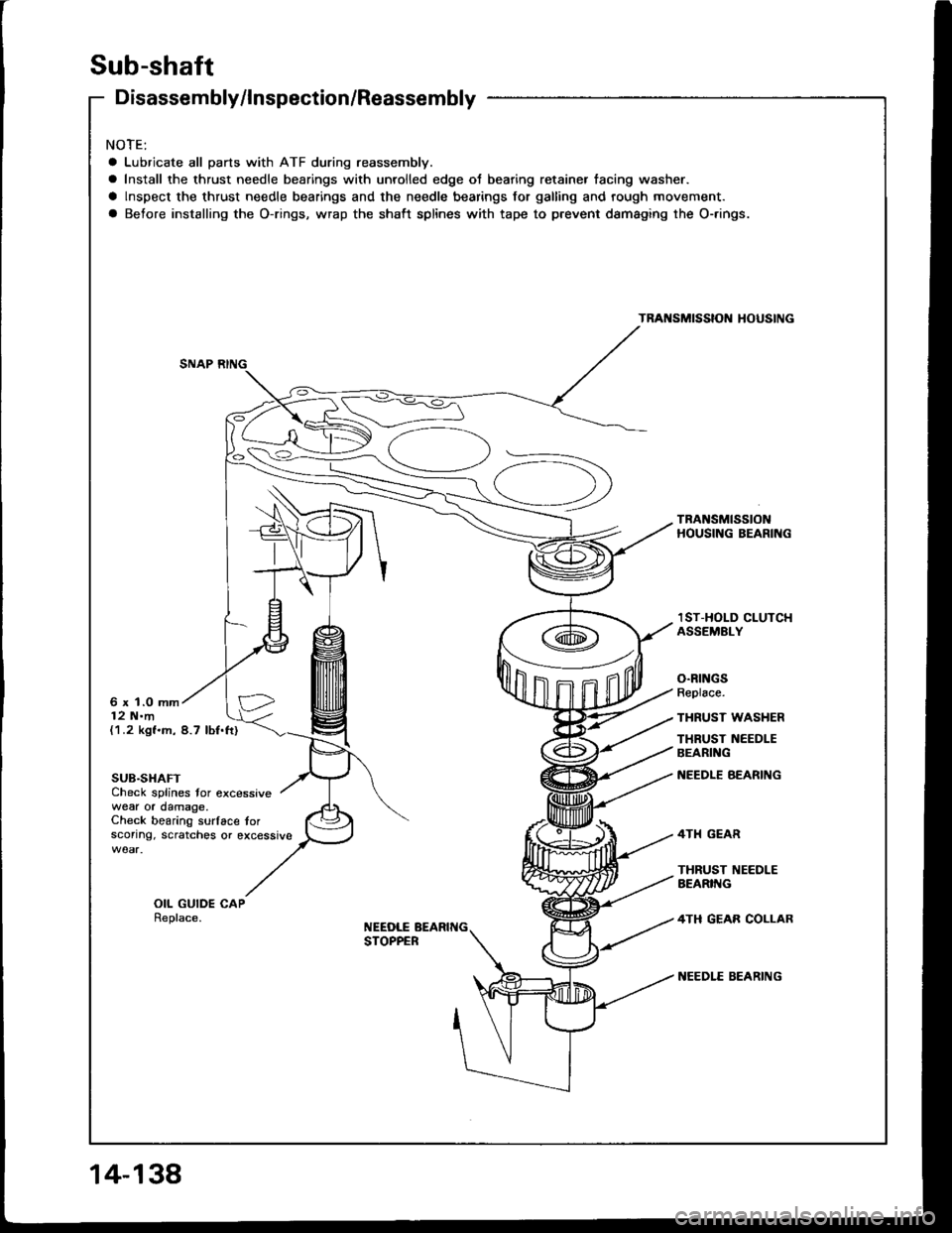
Sub-shaft
Disassembly/lnspection/Reassembly
NOTE:
a Lubricate all parts with ATF during reassembly.
a Install the thrust needle bearings with unrolled edge ot bearing retainer tacing washer.
a lnspect the thrust needle bearings and the needle bearings for galling and rough movement.
a Before installing the O-rings, wrap the shaft splines with tape to prevent dsmaging the O-.ings.
TRANSMISSIOI{ HOUSING
TRANSMISSIONHOUSING BEARING
6 x 1.0 mm12 N.m
lST-HOLD CLUTCHASSEMELY
O.RINGSReplace.
THRUST WASHER
THRUST NEEDLEBEARING
NEEDLE BEARING
4TH GEAR
THRUST I{EEDLEAEARIIIG
4TH GEAB COLLAR
NEEDLE EEARING
(1.2 kgf.m, 8.7 lbf.ft)
SUB.SHAFTCheck splines tor excessivewear or damage.Check bearing surlace torsconng. scratches or excessive
OIL GUIDE CAPReplace.NEEDLE BEARIT{GSTOPPER
Page 545 of 1413
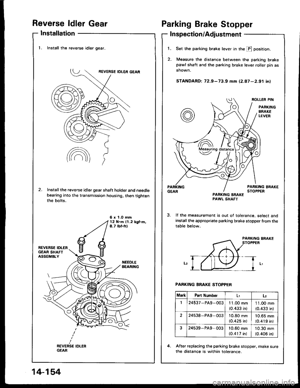
Reverse ldler Gear
Installation
Parking Brake Stopper
Inspection/Adjustment
1.
2.
Set the parking brake lever in the E position.
Measure the distance between the parking brakepawl shaft and the parking brake lever roller pin as
shown.
STANDARD: 72.9-73-g mm (2.87-2.91 in)
ROLLER PIN
PANKINGBRAKELEVER
PARKING BRAKESTOPPERPARKING BBAKEPAWL SHAFT
lf the measurement is out of tolerance, select andinstall the appropriate parking brake stopper from thetable below.
PARKING BRAKE STOPPER
After replacing the parking brake stopper, make su.e
the distance is within tolerance.
4.
7A\Meaauring\v
MarkPart NumbolLz
124537 - PA9- 0031 1.00 mm
{0.433 in}
11.00 mm
{0.433 in)
224538-PA9 -00310.80 mm(0.425 in)
10,65 mm(0.419 inl
24539- P49,00310.60 mm(0.417 in)
10.30 mm
{0.406 in)
1. Install the reverse idler gear.
Installthe reverse idle, gear shaft holder and needlebearing into the transmission housing, then tightenthe bolts.
6 x l.O mm12 N'm 11.2 kgt.m.4.7 lbf.ft)
14-154