roll HONDA INTEGRA 1994 4.G Repair Manual
[x] Cancel search | Manufacturer: HONDA, Model Year: 1994, Model line: INTEGRA, Model: HONDA INTEGRA 1994 4.GPages: 1413, PDF Size: 37.94 MB
Page 914 of 1413
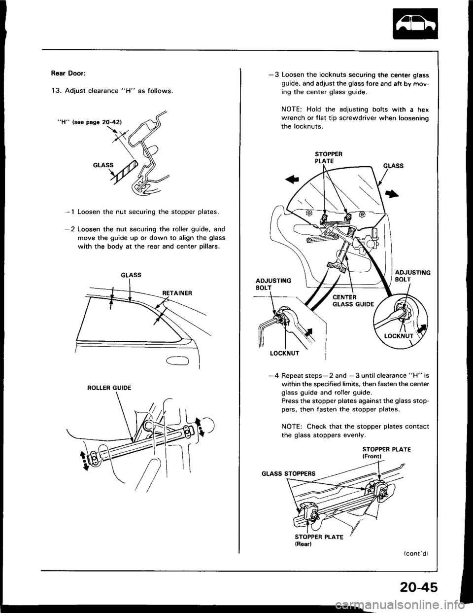
R6ar Door:
'13. Adjust clearance "H" as follows.
"H" lsos page 20-421
- 1 Loosen the nut securing the stopper plates.
2 Loosen the nut securing the roller guide, and
move the guide up or down to align the glass
with the body at the rear and center pillars.
GLASS
ROLLER GUIDE
-3 Loosen the locknuts securing the center glass
guide, and adjust the glass fore and aft by mov-
ing the center glass guide.
NOTE: Hold the adjusting bolts with a hex
wrench or tlat tip screwdriver when loosening
the locknuts.
I
-4 Repeat steps-2 and -3 until clearance "H" is
within the specified limits. then fasten the center
glass guide and roller guide.
Press the stopper plates against the glass stop-
pers, then fasten the stopper plates.
NOTE: Check that the stopper plates contact
the glass stoppers evenly.
STOPPER PLAYElF ontl
204s
Page 1039 of 1413
lllustrated Index
CAUTION:
a All SRS electrical wiling harnesses are covered with
y€llow insulation.
a Bafore disconnecting any pan of the SRS wile har-
ness. connect the sholt connectorlsl.
a Replace the sntire aflected SRS halness assembly if
it has an open circuit or damaged wiring.
NOTE: The original radio has a coded thelt protection
circuit. Be sure to get the customer's code number before- disconnecting the battery.- removing the No. 32 (7.5 Al fuse lrom the under-
hood fuse/relav box.- removing the radio.
After service, reconnect power to the radio and turn it
on. when the word "CODE" is displayed, enter the cus-
tomer's 5-digit code to restore radio operation.
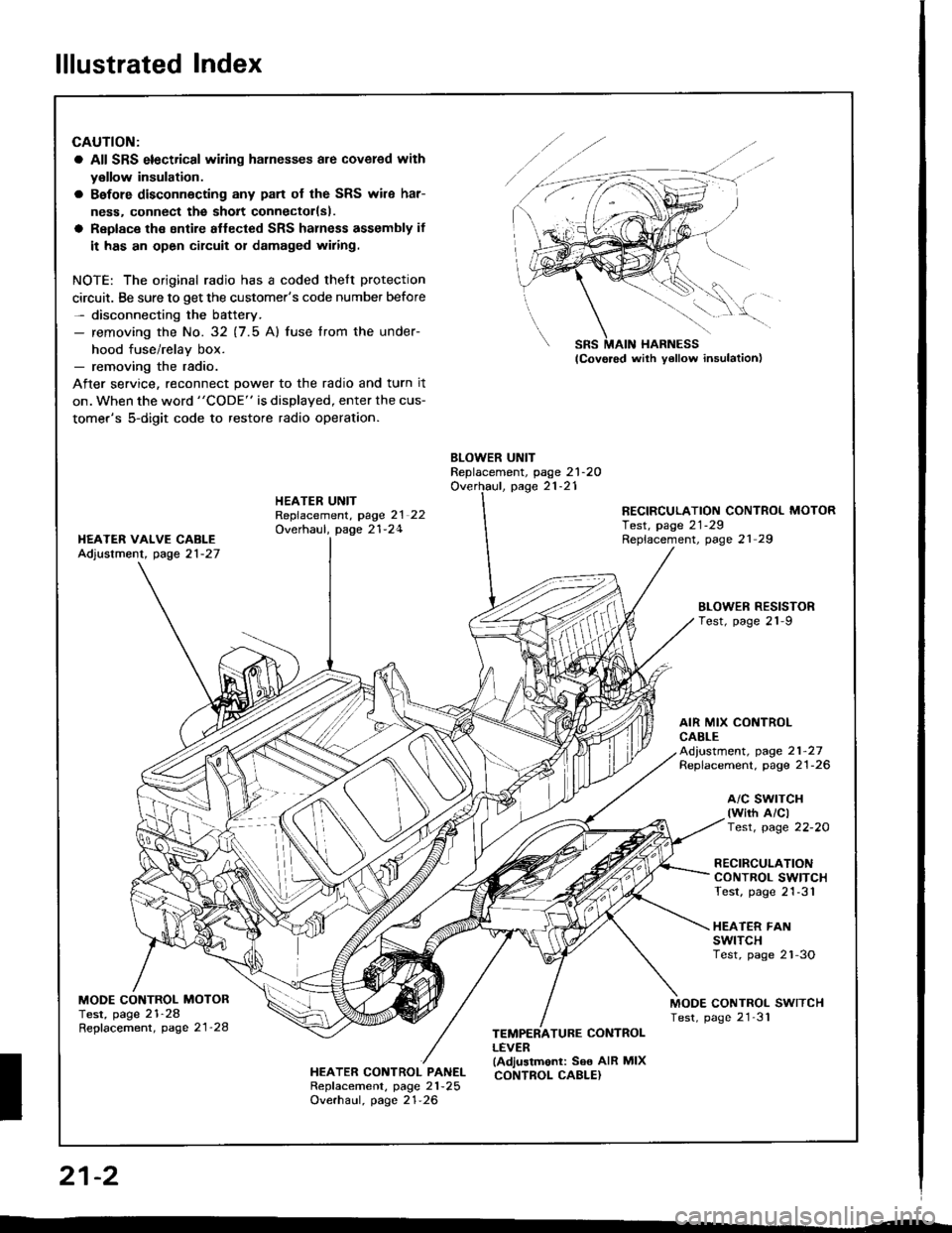
BLOWER UNITReplacement, page 21-2OOverhaul, page 21-21HEATER UNITRepfacement, page 2l 22Overhaul, page 21-24
RECIRCULATION CONTROL MOTORTest, page 21-29Replacement, page 21 29I{EATER VAIVE CABLEAdjustment, page 21-27
BLOWEN RESISTORTest, page 21-9
AIR MIX CONTROLCABLEAd,ustment, page 21-27Replacement. page 21-26
a/c swrTcH(wirh A/clTest, page 22-20
RECIRCULATIONCONTROL SWITCHTest, page 21-31
HEATER FANswtTcHTest, page 2'l-3O
MODE CONTROL MOTORTest, page 21-28Repfacement, page 21'28
MODE CONTROL SWITCHTest, page 21'31
HEATER CONTROL PANELRepf acement, page 21 -25
Overhaul, page 21-26
TEMPERATURE CONTROLLEVER(Adjustmonl: See AIR MIXCONTROL CABLE}
SRS MAIN HARNESS
W,
21-2
I
Page 1052 of 1413
From page 21-14
NO
To psg6 2'l - 16
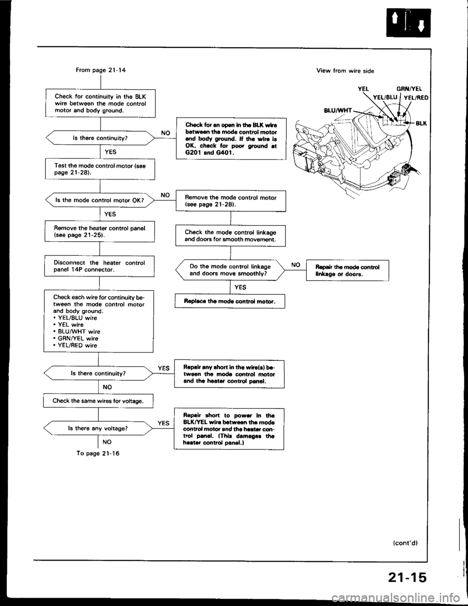
Check for continuity in the BLKwire betweon the mode controlmotor and body ground.
Chock lor an op6n In tho BLK wtbotwo€n tho modo control mototlnd body ground. It thr wlro i!OK, chock for poo. grouhd otG2O1 8nd G/tOl.
Test the modo control motor (seepage 21-281.
Romovo the mode control motor(soo pag6 21-281.ls the mode control motor OKI
Remove the heater control oanel{soe page 21-25).Ch€ck the modo control linkagoand doo.s tor smooth movoment.
Disconnect the heater controlDanel 14P connector.Do tho mode control linkageand doorc movs smoothlv?Ropair th6 mod6 controllinkago or doors.
Ch€ck each wire for continuity bo-twoon the mod6 control motorand body ground.. YEL/BLU wire. Y€L wire. 8LU,^/VHT wire. GRNI/EL wire. YEL/RED wire
Raplace thc modo control moto..
Roprir any .hort in th. wlrol!) b.-tworn tha moda control anototand tha holtar control pan6l.
Check the same wires lor vohage.
Roplir rho.t to powar In tha8LK^'EL wiro b.two.h lh. modoconlrol hotor rnd tha haat* con-trol p!rr.|. (Thi! damrg.. thahello. control p!nel.)
ls the.6 any voltage?
View lrom wi.e side
GRl{/YEL
lconl'dl
21-15
Page 1055 of 1413
Troubleshooting
Recirculation Control Motor (cont'd)
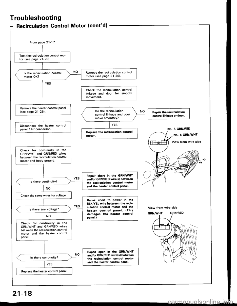
Test the recirculation control mo_
tor (see page 21-29).
Remove the recirculation control
motor (see pag. 21-291.ls the recirculation controlmotor OK?
Check the recirculation controllinkage and door for smoothmovement.
Remove the heater control pan€l
{see page 21-25).Do the recirculationcontrol linkage and doormove smoothly?
Ropalr tho ioclrculatiooconirol linkaga ot dool.
Disconnect the heater controlpanel 14P connector.
Check for continuity in the
GRNMHT and GRN/RED wires
between the recirculation controlmotor 6nd body ground.
RoDair shorl in rhs GRNMHT
and/or GRN/RED witols) botwoenthe rocirculation conl.ol motot
and tho hoster control Panol.
Check the same wircs for voltage.
Ropair 3hon lo Power in thoBLK/YEL wiro botwoon ths rocit-
culalion control motoi and lheho6tor control Panel' {Thirddmagos tho h€atot cont.ol
oanol.)
ls there any voltage?
Check for contin!ity in the
GRN/WHT and GRN/RED wires
between the recirculation controlmotor and the heater controlpanel.
Ropair opsn in the GRi|/WHTand/o. GRN/RED wiro{sl botwoonths rocirculstion conttol mototand tho hoator control Panol.
Reolace th€ heatsr control Panal.
From page 21- l7
No. 5 GRN/RED
o. 6 GRI{MHT
View from wire side
View from wire sid6
GRN/RED
ffii
21-18
Page 1056 of 1413
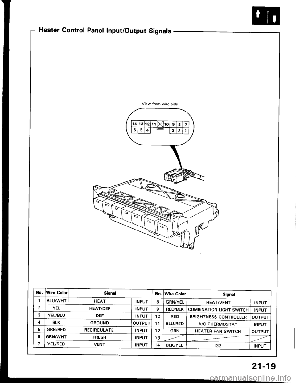
Heater Control Panel Input/Output Signals
No.Wire ColorSignslNo.Wire ColorSi9n8l
IBLU/WHTHEATINPUT8GRN/YELHEATA/ENTINPUT
2YELI{EAT/DEFINPUTqRED/BLKCOMBINATION LIGHT SWITCHINPUT
YEL/BLUDEFINPUT10REDBRIGHTNESS CONTROLLEROUTPUT
4BLKGROUNDOUTPUT11BLU/REDA/C THERMOSTATINPUT
5GRN/REDRECIRCULATEINPUT12GRNHEATER FAN SWITCHOUTPUT
oGRN/WHTFRESHINPUT1?
YEL/REDVENTINPUT't4BLK/YELtG2INPUT
21-19
Page 1138 of 1413
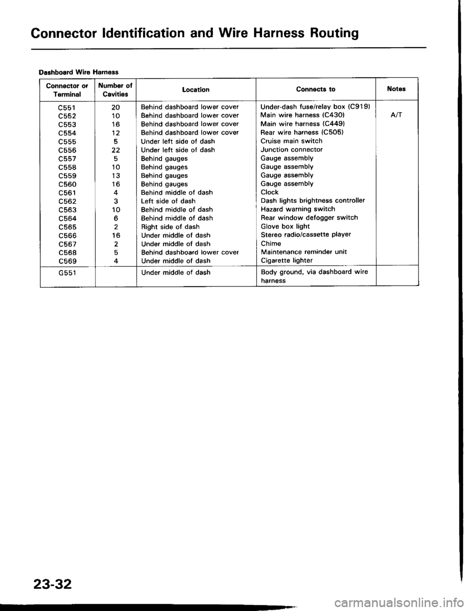
Connector ldentification and Wire Harness Routing
Dashboard wile Ha.n6ss
Connector ot
T€rminal
Number of
Caviti6sLocationConnects toNotes
c553
c554
L55b
c556
c557
c558
c560
LCO I
c563
c564
c565
c566
c567
c568a 6ACl
20
10
to
12
5
22
10
13
16
10
6
to
2
Behind dashboard lower cover
Behind dashboard lower cover
Behind dashboard lower cover
Behind dashboard lower cover
Under lett side oJ dash
Under left side of dash
Behind gauges
Behind gauges
Behind gauges
Behind gauges
Behind middle of dash
Left side of dash
Behind middle of dash
Behind middle of dash
Right side of dash
Under middle of dash
Under middle of dash
Behind dashboard lower cover
Under middle of dash
Under-dash fuse/relay box (C919)
Main wire harness (C43Ol
Main wire harness (C4491
Rear wire harness {C505)
Cruise main switch
Junction connector
Gauge assembly
Gauge assembly
Gauge assembly
Gauge assembly
Clock
Dash lights brightness controller
Hazard warning switch
Rear window defogger switch
Glov€ box light
Stereo radio/cassette PlaYer
Chime
Maintenance reminde. unit
Cigarette lighter
Afi
Under middle of dashBody ground, via dashboard wire
harness
23-32
Page 1168 of 1413
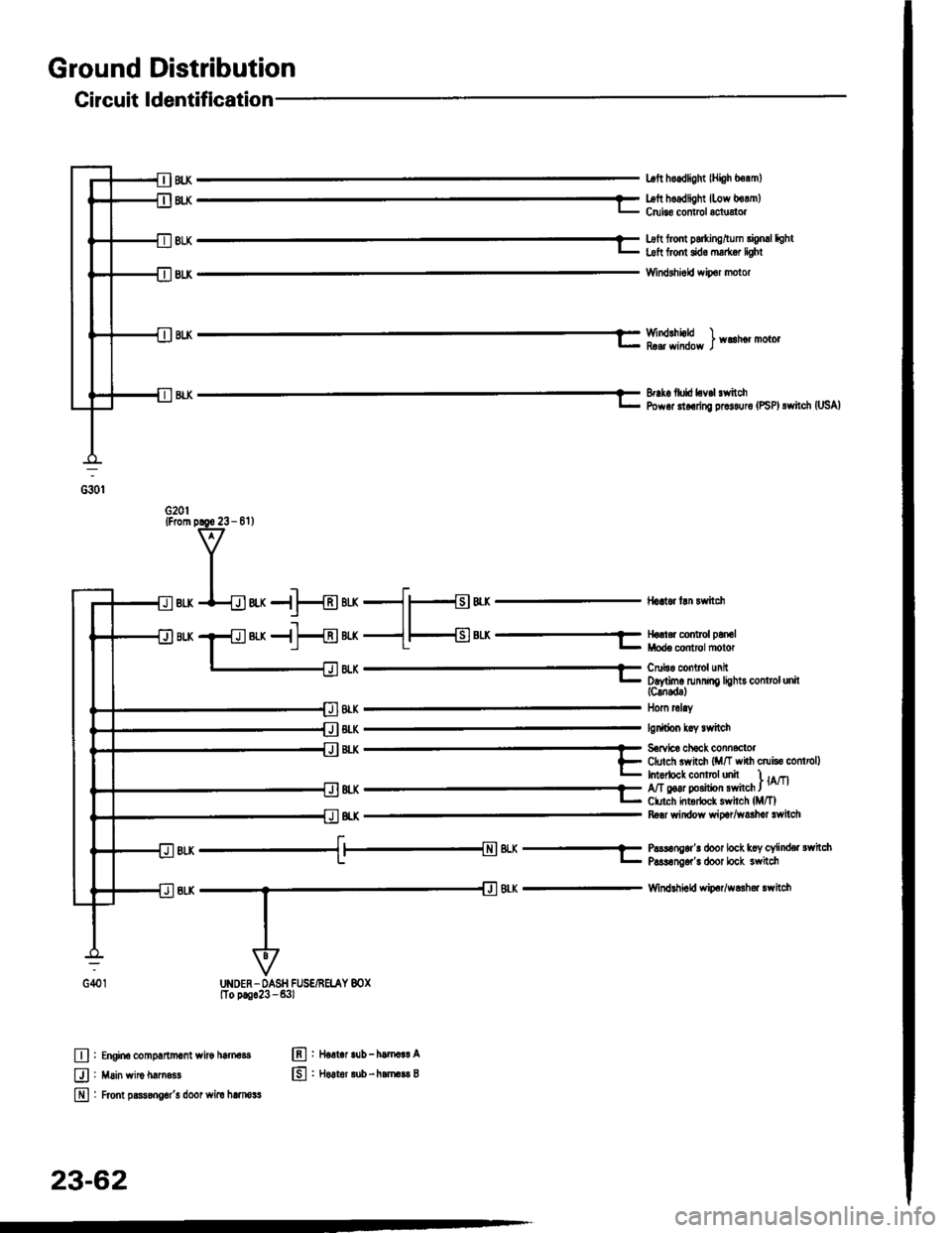
Ground Distribution
Circuit ldentification
lHi0h berm)
'LK H[l[llsf#"ff'"Jfl1"'o"
Hom rol.y
lgdtion koy lrvitch
8r -;€[email protected]*'*.,F Cftxch svynch {M/T whh cruisc controllL Intorlocl conlrclunit I lArtoq_r- Ct rch htodock swhch lM/TlRa'r window wioar/washot lwitdl
t.BIK -{ |-{N�| 4.X -7 P!.rsong.r'! doot loct kcy cylind€r sYritchl- - l- P!s!6n06r's door bck 3witch
Windlhiald wio.r/w$h6r rwhch
Engin6 comprrtmonl wiro htrnds
Main wiro hftn.ss
Frcnt prsongor'! door wim hlmosg
llort.| lub - hamar! A
H6!t6r lub - harara$ B
BIK
@:
tlt .tr
tr
E
23-62
Page 1186 of 1413
![HONDA INTEGRA 1994 4.G Repair Manual Starting
Startel
System
Overhaul
from clutch side.
-s@]
MOLYBDENUMDISULFIDE
CAUTION: Disconnecl th€ battery n€gative cable befole
lomoving the startet.
NOTE: The original radio has a coded theft p HONDA INTEGRA 1994 4.G Repair Manual Starting
Startel
System
Overhaul
from clutch side.
-s@]
MOLYBDENUMDISULFIDE
CAUTION: Disconnecl th€ battery n€gative cable befole
lomoving the startet.
NOTE: The original radio has a coded theft p](/img/13/6067/w960_6067-1185.png)
Starting
Startel
System
Overhaul
from clutch side.
-s@]
MOLYBDENUMDISULFIDE
CAUTION: Disconnecl th€ battery n€gative cable befole
lomoving the startet.
NOTE: The original radio has a coded theft protection
citcuit. Be sure to get the customer's code number before
- disconnecting the batterY.- removing the No.3 2 (7.5 A) fuse from the under-hood
fuse/relay box.- removing the tadio.
Atter service, reconnect power to the radio and turn at
on. When the word "CODE" is displayed, enter the cus-
tomer's 5-digit code to restore radio operation.
tr./.' BRUSH HOLDERTest, page 23-8'l
ERUSH
COVER
I
6
OVERRUNNING CLUTCH ASSEMBLYInspection, page 23_84
SOLENOIDPLUNGERInspection, page 23-85
BRUSH HOLOER
ARMATURE
STARTERSOLENOIDTest, page 23-78
PINION GEAR IDLER GEAR
Inspection, page 23-11
IDLER GEAR
I
@*
SOLENOID HOUSING
HARNESS BRACKET
STEEL BALL
install steel ball
lnspection and Test,page 23-82
ROLLER BEARINGSand CAGEPrevenl rollers trom being scattered and lost.
MOLYBDENUM DISULFIDE
_R1
MOLYADENUMDISULFIDE
23-80
ENO COVER
ARMATURE
GEAR HOUSING
Page 1242 of 1413
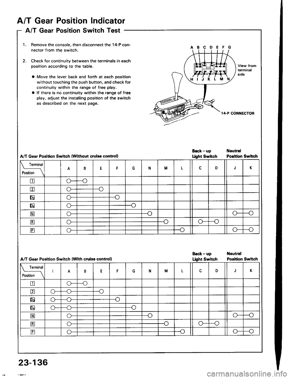
A/T GearPosition Indicator
A/T GeaPosition Switch Test
23-136
1.
2.
I I gear Fosluon Dwtrcn I esr -
Remove the console. then disconnect the 14-P con-
nector from the switch.
Check for continuitv between the terminals in each
position according to the table.
a Move the lever back and forth at each position
without touching the push button, and check tor
continuity within the range of free play.
a lf there is no continuity within the.ange of free
play, adjust the installing position ol the switch
as described on the next page.
A/T Goar Position Swhch (Without crulso contloll
A/T Goar Position Switch (With cruiss controll
tgrminal90e
14-P CONI{ECTOR
Back-up Noutrrl
Ught Swhch Polition Swhch
Back-up t{outral
Llght Swltch Potidon Swltch
Terminal
P*ii-_\BFNMDK
tro-
ao---o
Eo---o
Eo-
No--.oo-
tro--oo---o
tro---oo---o
Terminal
P*,i-
_\6NMDJK
tro---o
ao---.o
Eo---o
E--o
EG_o-
Eo-o---o
Eo---oo---o
Page 1261 of 1413
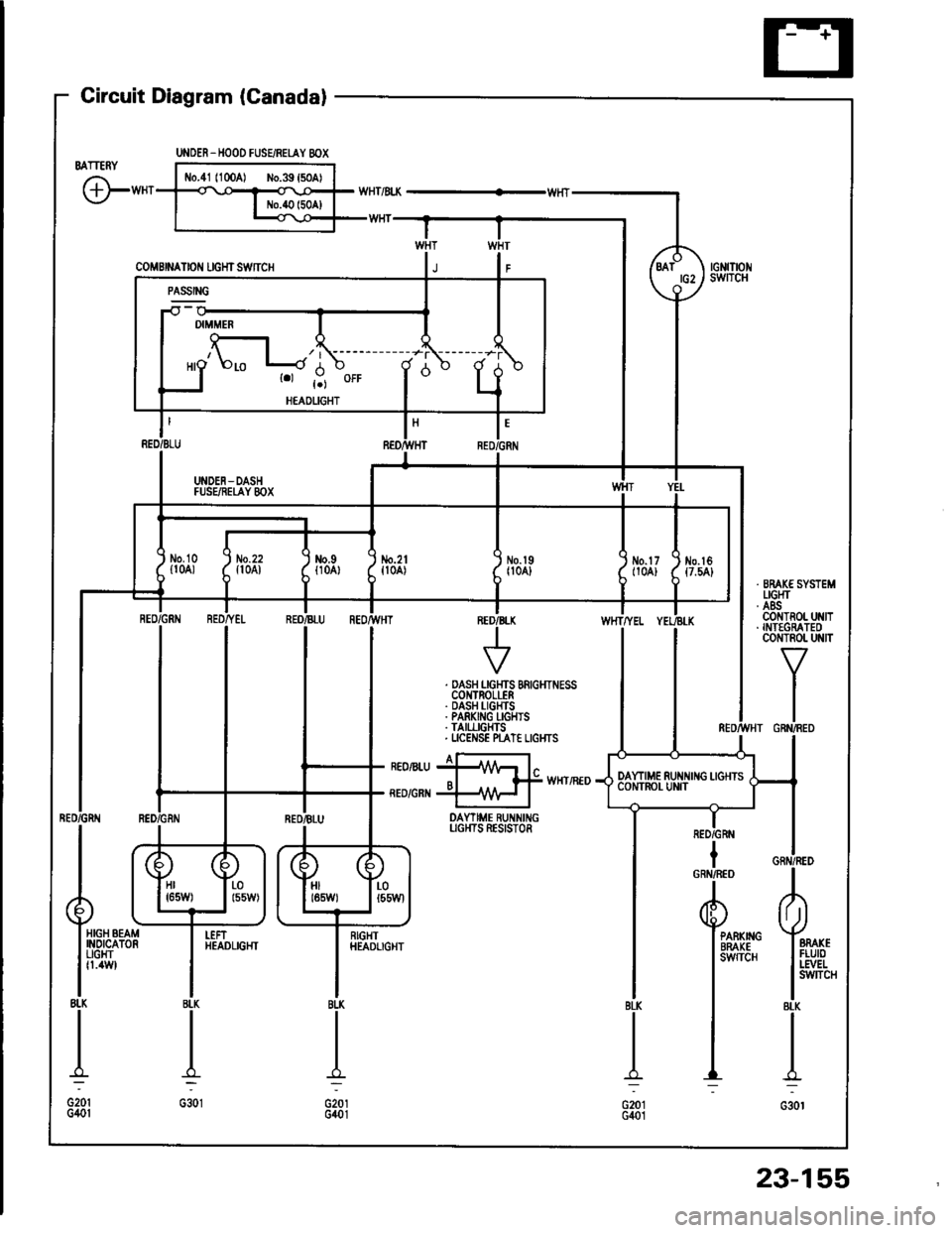
Gircuit Diagram (Canadal
BATTERY
G"*
UNOER_HOOD FUSEiRETAY 8OX
coMBrNAtor{ rcHrswnc
-il w
| '.=r" I
ll'L I I
I I *o\." l-'li' ;- ;j
I LI
"- r.r-,9 "orr
I
d "
L
RED/BLU REO/}VHT RED,ll
I UNDEN-DASH II FUSEiIEI,AY 8OX I
tl
L-J
t'GRN
/d\BATtG2\9-l
rGNrTrot{swITcH
No.2lfl0A)\I
No.l9|l04]Jm.tr (
t10A) ttt
I
No.l6{7.54}
tl
i,"#
llrrff li'rrt,
RED/GRtIIBLU REOr'TVHTINED/B
V
WHTTYEL
. DASH LGHTS BRIGHTNESSCOI{TROLLER. DASH I-IGHTS. PARKING I-GHIS. TAII,LIGHTS. UCENSE N"AT€ LIGI{TS
I a-rneonru jllA/Vr l"o I f# wxrintoRED/GRI{ +\{H I
DAYTIME RUNNINGUGI{TS RESISTOR
IRED/GRN
Hr I r-01651,1/) | l55W)HIt85W)LOt55Wl
HIGH BEAMINOICATORUGHTfl.4W
I
RIGHTHEADLIGHTPARKIIIGBRAKEsw{TcH
23-155