roll HONDA INTEGRA 1994 4.G Service Manual
[x] Cancel search | Manufacturer: HONDA, Model Year: 1994, Model line: INTEGRA, Model: HONDA INTEGRA 1994 4.GPages: 1413, PDF Size: 37.94 MB
Page 600 of 1413
Driveshafts
Reassembly (cont'dl
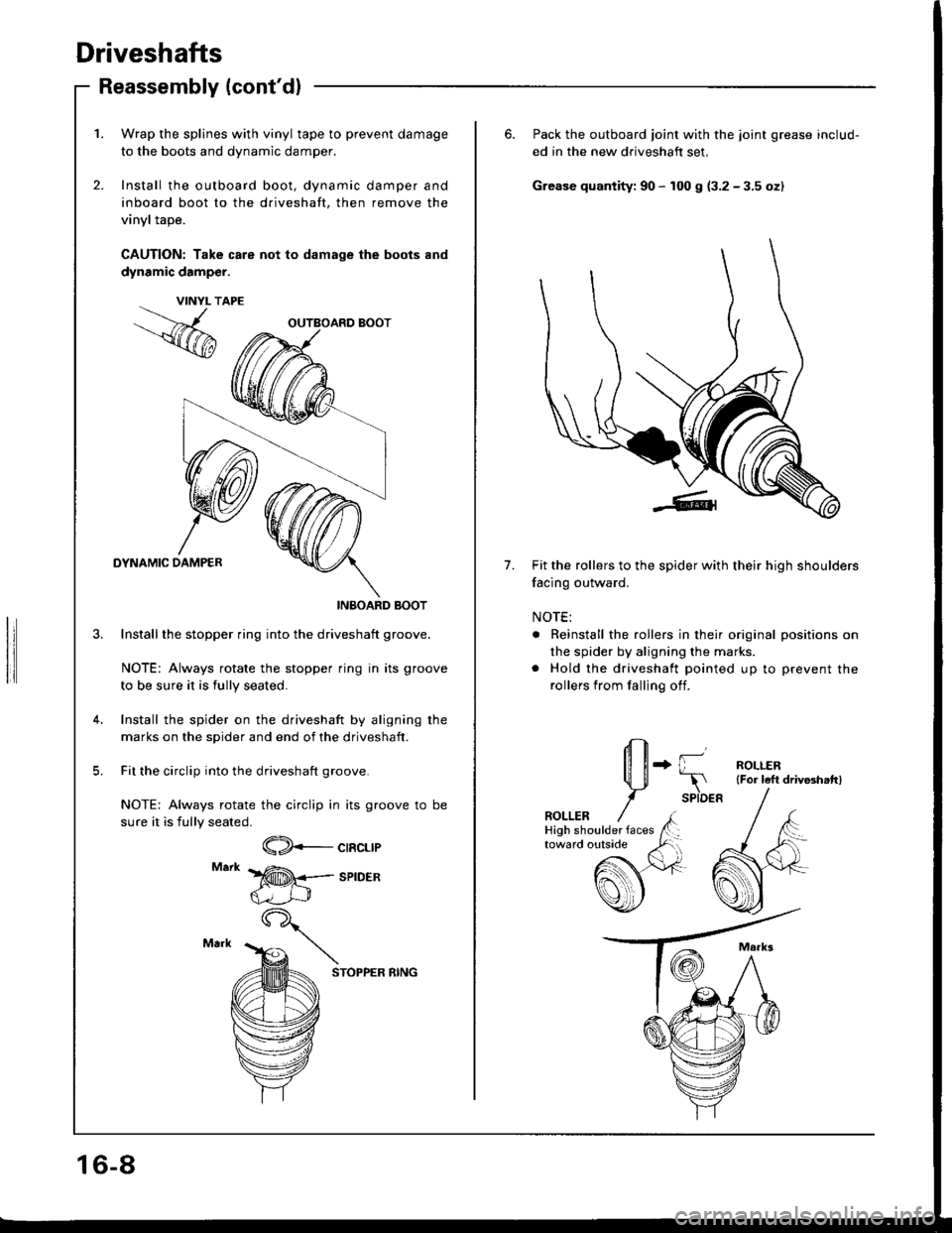
1. Wrap the splines with vinyl tape to prevent damage
to the boots and dynamic damper.
2. Install the outboard boot, dynamic damper and
inboard boot to the driveshaft, then remove the
vinyl tape.
CAUTION: Take care not to damage the boots and
dynamic damp€r.
DYNAMIC DAMPER
INBOARD BOOT
Installthe stopper ring into the driveshaft groove.
NOTE: Always rotate the stopper ring in its groove
to be sure it is fully seated.
Install the spider on the driveshaft by aligning rhe
marks on the spider and end of the driveshaft.
Fit the circlip into the driveshaft groove.
NOTE: Always rotate the circlip in its groove to be
sure it is fully seated.
VINYL T
,.%
CIRCLIP
SPIDER
STOPPER RING
OUTBOARD BOOT
16-8
6. Pack the outboard joint with the joint grease includ-
ed in the new driveshaft set,
Grease quantity: 90 - 100 g (3.2 - 3.5 oz)
7.Fit the rollers to the spider with their high shoulders
facing outward.
NOTE:
. Reinstall the rollers in their original positions on
the spider by aligning the marks.
. Hold the driveshaft pointed up to prevent the
rollers from falling off.
+ {l--r
SPIDER
ROLLER{For left driv8hattl
ROLLER
Page 601 of 1413
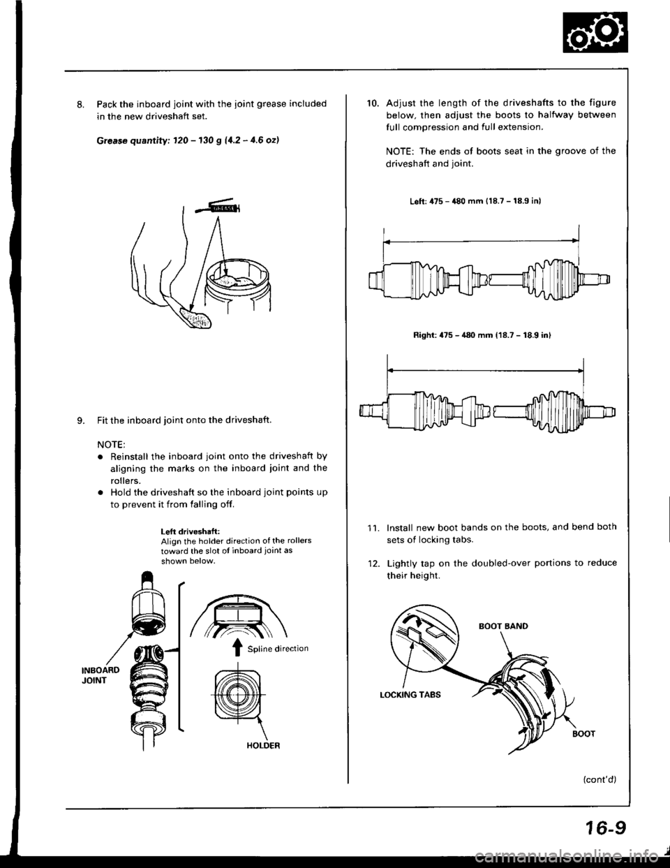
8.Pack the inboard joint with the ioint grease included
in the new driveshaft set.
Grease quantity; 120 - 130 g 11.2 - 4.6 ozl
9. Fit the inboard joint onto the driveshaft.
NOTE;
. Reinstall the inboard joint onto the driveshaft by
aligning the marks on the inboard ioint and the
rollers.
. Hold the driveshaft so the inboard joint points up
to prevent it from falling off.
Left drivoshaft:Align the holder direction of the rollers
toward the slot ot inboard joint as
INBOARDJOINT
/,.-:--\ \
I sotine di,ection
A\
{(@}
HOLDER
10.Adjust the length of the driveshafts to the figure
below. then adjust the boots to halfway between
full compression and full extension.
NOTE: The ends of boots seat in the groove of the
driveshaft and joint.
Left: 475 - 480 mm {18.7 - 18.9 inl
Right: 475 - 480 mm (18.7 - 18.9 inl
lnstall new boot bands on the boots, and bend both
sets of locking tabs.
Lightly rap on the doubled-over portions to reduce
their height.
{cont'd)
11.
16-9
Page 612 of 1413
Construetion
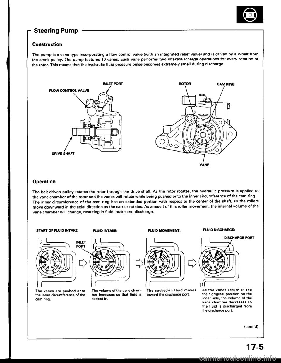
The pump is a vane-type incorporating a flow control valve (with an integrated relief valve) and is driven by a V-belt from
the crank pulley. The pump features 10 vanes, Each vane performs two intake/dischsrge operations for every rotation of
the rotor. This means that the hydraulic fluid pressure pulse becomes extremely small during discharge.
CAM RING
FLOW CONTBOL VALVE
DRIVE
Operation
The belt-driven pulley rotates the rotor through the drive shaft, As the rotor rotates, the hydraulic pressure is applied to
the vane chamber of the rotor and the vanes witl rotate while being pushed onto the inner circumference of the cam .ing.
The inner circumference of the cam ring has an extonded portion with respect to the center of the shaft. so the rollers
move downward in the axial direction as the carrier rotates. As a result of this roller movemsnt, the internal volume of the
vane chamber will change, resulting in fluid intake and discharge.
START OF FLUID INTAKE:FLUID INTAKE:FLUID MOVEMENT:FLUID DISCHABGE:
DISCHARGE P('BT
I
SHAF'
The vanes are pushed ontothe inner circumference of th6cam ring.
Th6 volums otth€ van€ cham-ber increasos so that lluid issuckod in.
Th6 sucked-in fluid moves
towsrd the discha196 pon.As the vanes return to th€their original position on theinner side, the volume of thevane chamber decreases sothe fiuid is discharg6d fromthe discharge port.
(cont'd)
INLET PORT
VANE
Page 645 of 1413
Power Steering Pump
Disassembly {cont'd}
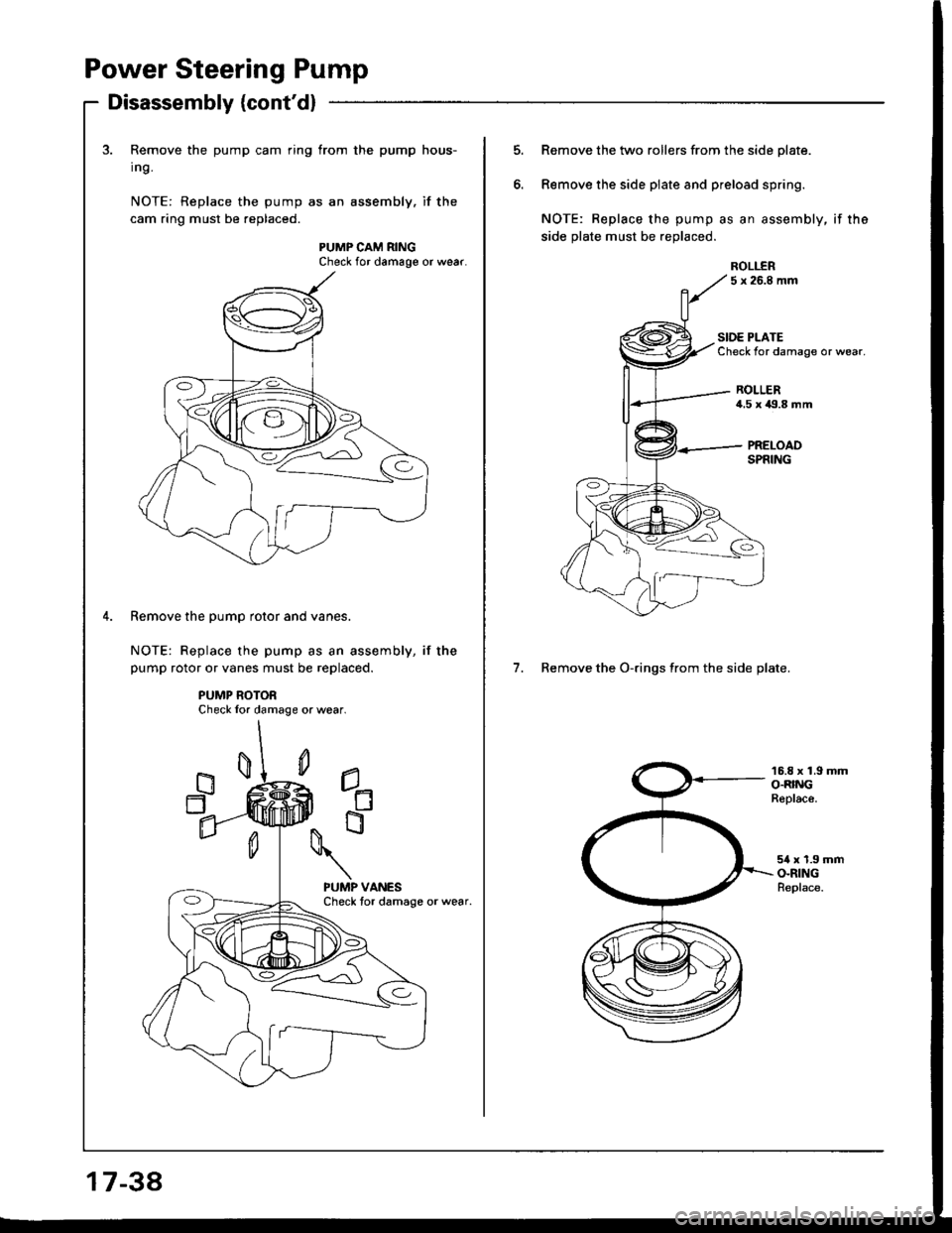
3. Remove the pump cam ring from the pump hous-
Ing.
NOTE: Replace the pump as an assembly. if the
cam ring must be replaced.
PUMP CAM RINGCheck for damage or wear.
Remove the pump rotor and vanes.
NOTE: Replace the pump as an assembly, if the
pump rotor or vanes must be replaced.
PUMP ROTORCheck lor damage or wear.
1734
Remove the two rollers from the side plate.
Remove the side piate and preload spring.
NOTE: Replace the pump as an assembly, if the
side plate must be replaced.
5 x 26.8 mm
7. Remove the O-rings from the side plate.
SIDE PLATECheck for damage or wear.
ROLLER4,5 x 119.8 mm
16.8 x 1.9 mmO.RINGReplace.
54 x 1.9 mmO-RINGReplace.
ROLI..ER
Page 647 of 1413
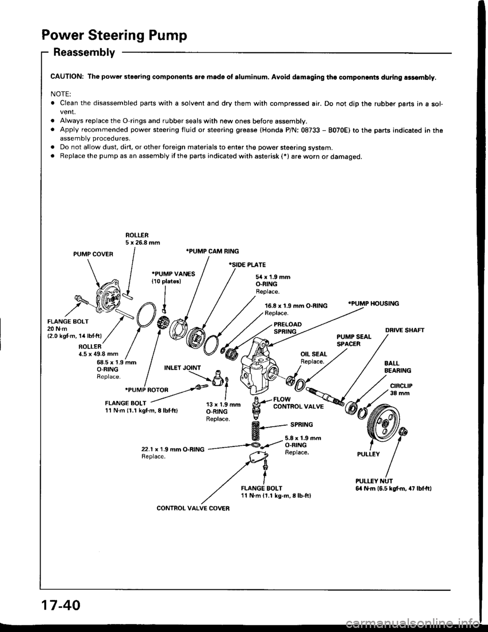
Power Steering Pump
Reassembly
CAUTION: The power steering componsnts are mado of sluminum. Avoid dsmaging th€ componcnts during assombly,
NOTE:
. Clean the disassembled pans with a solvent and dry them with compressed air. Do not dip the rubber parts in a sofvent.
. Always replace the O-rings and rubber seals with new ones before assembly.. Apply recommended power steering fluid or steering grease (Honda P/N: 08733 - B070E) to the parts indicated in theassemblv procedures.
. Do not allow dust, dirt, or other foreign materials to enter the power steering system.. Replacethe pump asan assembly ifthe parts indicated with asterisk (*) are worn or damaged.
ROLLER5 x 26.8 mm
PUMP covEn /
."'MP cAM RING
, / .",or r*r,
^ / -e^urrae vrues / / sirx1.smm
\Al {ro pratesl I / o_nrNc
dA-h1//EZil*l///'^ee'ace
o-ntNGReplace.
16.8 x 1.9 mm O-RING
\A I {ro Platesl
,h$;@:",n1
i'"otr
/-V#mtt.m,1a|t�t.fti// / / \E
RoLLER / |a.5 x ag.a mm / |68.5 x 1.9 mm Io-RING / INLET
Reptace.
I
.PUMP HOUSING
xf:.i'/pp@6{fr;ryDRIVE SHAFTPUMP SEALSPACERROLLER /1.5 x 49.8 mm /68.5 x 1.9 mmO-R|NG / INLET JO-INT
Replace.
I'PUMP ROTOR>ei
iiij:f:,ll-T;-,",,,, ll;il'- g--lblY""."*";
Replace. :
$+--- srntnc
E -5.8x1.9mm
22.r x r.9 mm o-RfNG ------t@-<'t o^::t:\-GReplace.Replace.
FLANGE BOLT'11 N.m 11.1 kg-m,8lb-ftI
17-40
CONTROL VALVE COVEN
Page 648 of 1413
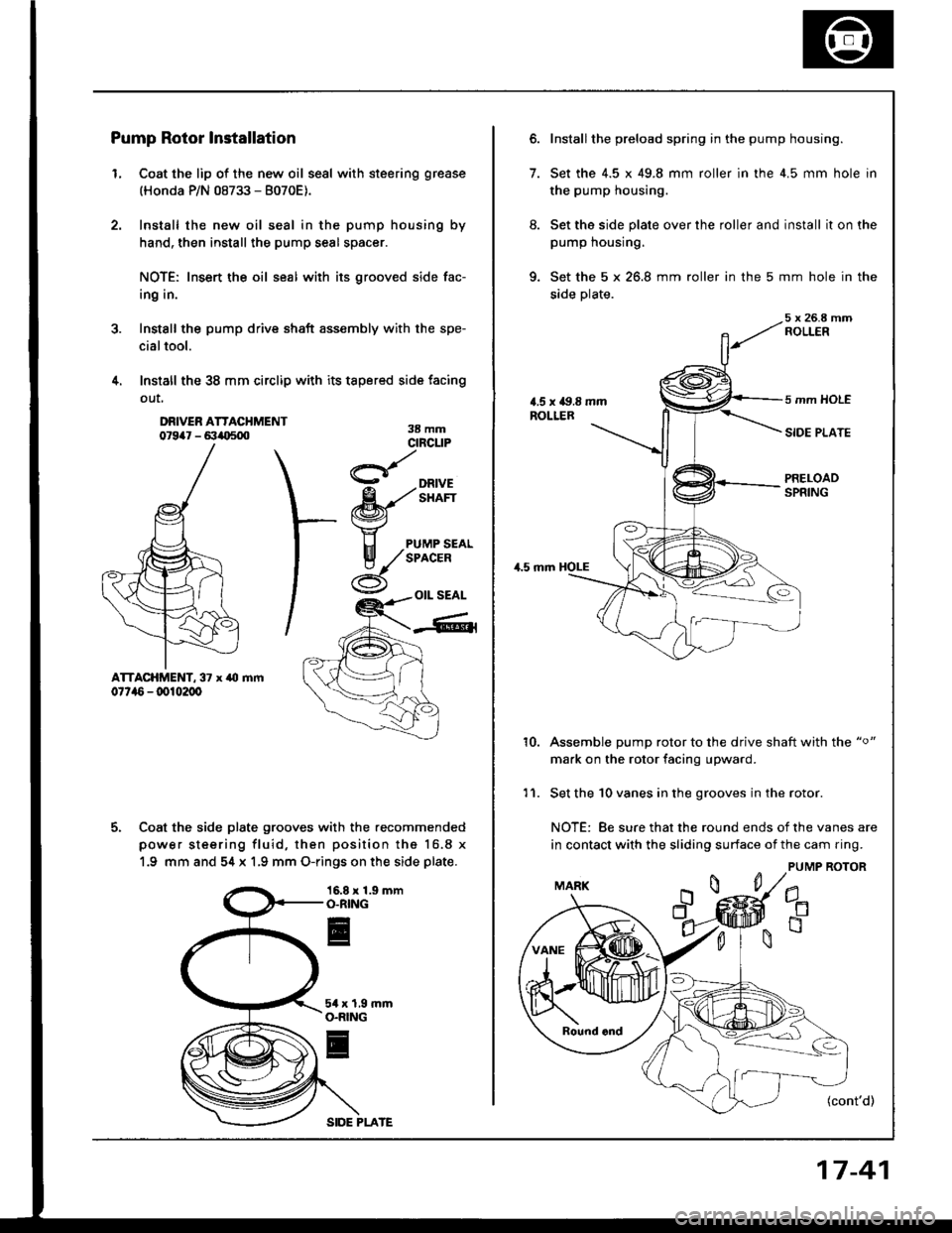
Pump Rotor Installation
L Coat the lip of the new oil seal with steering grease
(Honda P/N 08733 - 8070E).
Install the new oil seal in the pump housing by
hand, then install the pump seal spacer.
NOTE: Insert the oil seal with its grooved side fac-
ing in.
Install the pump drive shaft assembly with the spe-
cialtool.
Install the 38 mm circlip with its tapered side facing
out,
3.
4.
DRIVER ATTACHMENT07947 - 6:1io50038 mmcrncuP
- DRIVE
fu'/'i,Ert\=zl4
I"J PUMP SEALIf /sprcen
x,tY -ot seal
-Gll
ATTACHMENT, 37 x ,r0
07t,16 - dt102d,
5. Coat the side plate grooves with the recommended
power steering fluid, then position the 16.8 x
1.9 mm and 54 x 1,9 mm O-rings on the side plate.
16.8 x 1.9 mmO.RING
5a x 1,9O.RING
l
SIDE PLATE
17-41
6. Install the preload spring in the pump housing.
7. Set the 4.5 x 49.8 mm roller in the 4.5 mm hole in
the pump housing.
8. Set the side plate over the roller and install it on the
pump housrng.
9. Set the 5 x 26.8 mm roller in the 5 mm hole in the
side plate.
5 x 26.8 mmROLLER
5 mm HOLE
SIDE PLATE
PRELOADSPRING
,1.5 mm
10.Assemble pump rotor to the drive shaft with the "o"
mark on the rotor facing upward.
Set the 10 vanes in the grooves in the rotor.
NOTE: 8e sure that the round ends of the vanes are
in contact with the sliding surface of the cam ring.
PUMP ROTOR
(cont'd)
11.
Page 649 of 1413
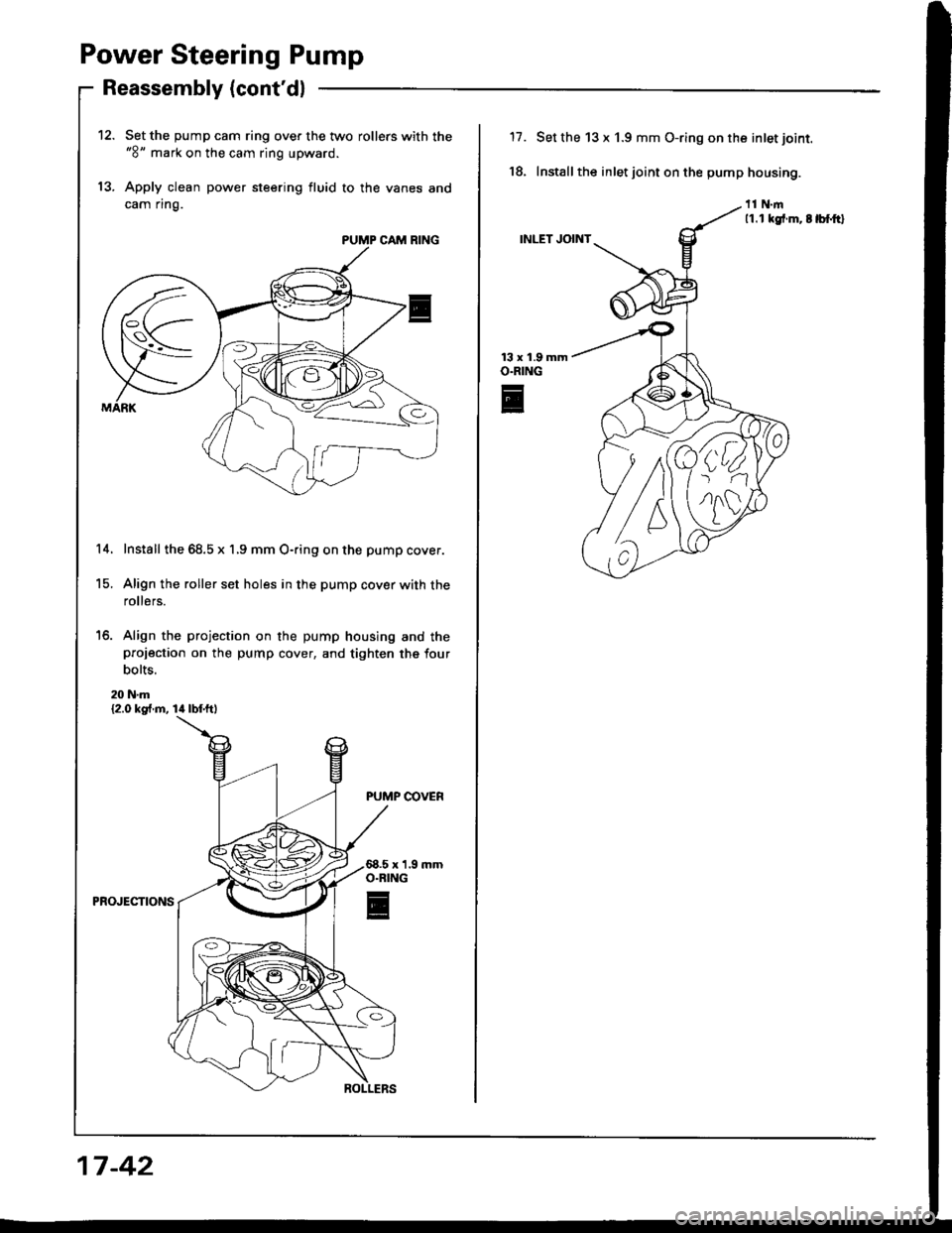
Power Steering Pump
Reassembly (cont'dl
Set the pump cam ring over the two rollers with the"8" mark on the cam ring upward.
Apply clean power steering fluid to the vanes and
cam ring.
Install the 68.5 x 1,9 mm O-ring on the pump cover.
Align the roller set holes in the pump cover with the
rollers.
'16. Align the projection on the pump housing and theprojection on the pump cover, and tighten the four
bolts.
20 N.m{2.0 kg .m, lil lbf.ftl
PUMP COVER
PROJECTIONS
13.
PUMP CAM RING
14.
15.
17 -42
17.
18.
13 x 1.9O.RING
E
Set the 13 x 1.9 mm O-ring on the inlet joint.
Install the inlet joint on the pump housing.
11.1 kgt.m. t lbf.ftl
INLET JOINT
T9
Page 659 of 1413
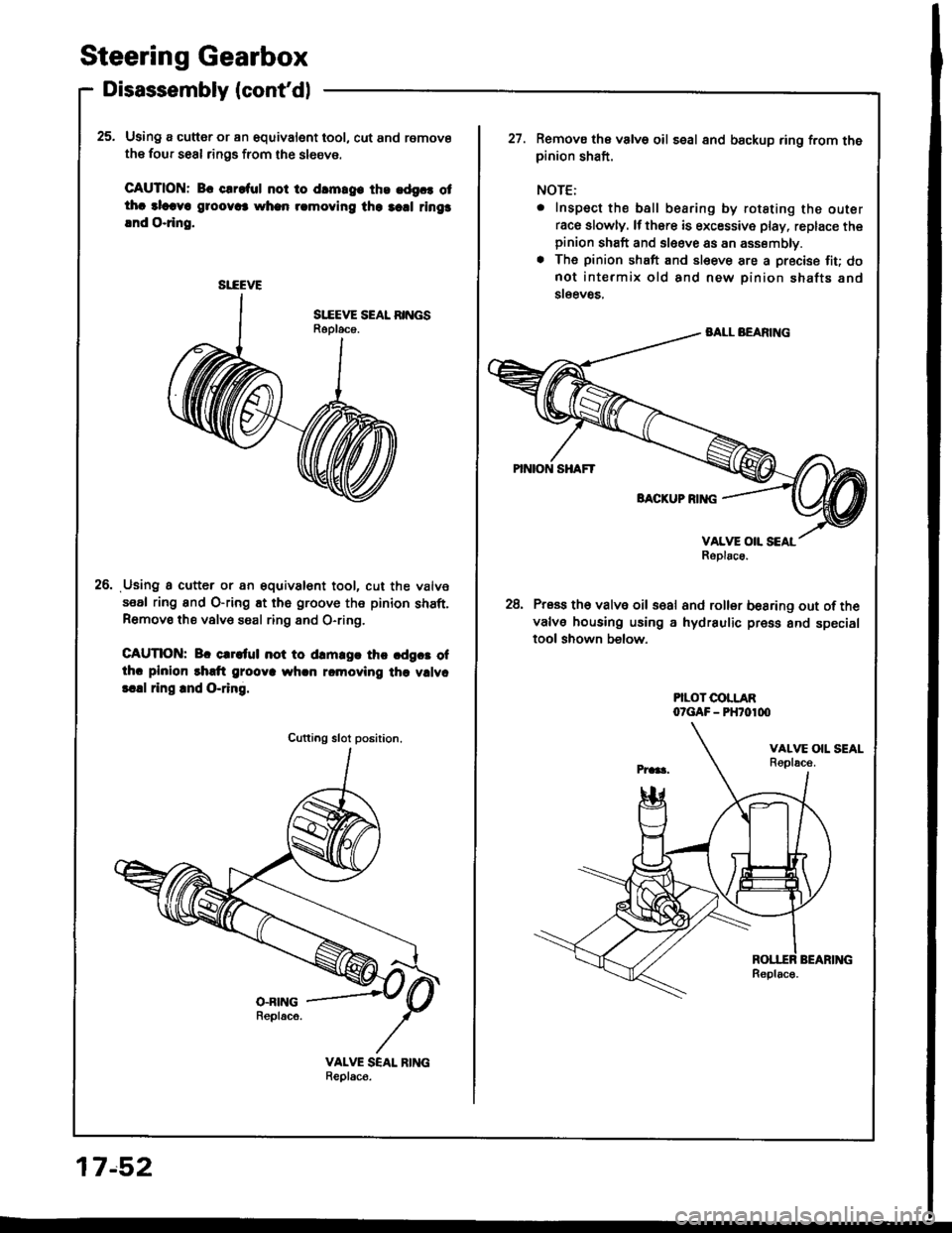
Steering Gearbox
Disassembly (cont'dl
25. Using a cutter or an equivalent tool, cut and remove
the four seal rings from the sl6eve.
CAUTION: Bc clroful not to drmrg. ths .dgc. otthc alcava g1oov6 whan rcmoving the 3cd rings
lnd O.ring.
Using a cutter or an gquivalent tool, cut the valve
seal ring and O-ring Et the groove the pinion shaft.Remove the valv€ saal ring 8nd O-ring,
CAUTION: Br crrltul not to drm.gr thc cdgct ofthc plnion rhdt grooya whcn rcmoving the vllvc
!.!l ring rnd O-ring.
26.
SI-EEVE
Cutting slot position.
17.52
Remova the valve oil seal 8nd backup ring from thepinion shaft.
NOTE:
. Inspect the ball bearing by rotating the outer
race slowly. lf thsre is excessive play, replace thepinion shaft and sleeve as an assembly.. The pinion shaft and sleeve are a precise fiu donot intermix old and new pinion shafts and
steev8s,
28, Press th6 valve oil s€al and roller besring out ofthe
valve housing using a hydraulic press and specialtool shown below.
PILOT COLLARO?GAF - PHTO1OO
Page 663 of 1413
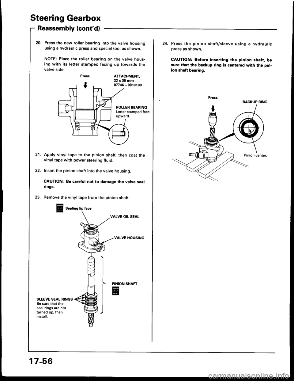
Steering Gearbox
Reassembly (cont'd)
SI,-EEVE SEAL RINGSBe sure that thesear ings are notturned up, theninstall.
Press the new roller bearing into the valve housing
using a hydraulic press and special tool as shown.
NOTE: Place ths roller bearing on the valve hous-
ing with its letter stamped facing up towards the
valve side.
Pr.33,
I
PINION
E
20.
ATTACHMENT,32x35mm077/aO - (x)1010O
ROLLER BEARINGLetter stamped face
21.Apply vinyl tape to the pinion shaft, then coat thevinyl tape with power steering fluid.
Insert the pinion shaft into the valve housing.
CAUTION: Be carotul not to damage tho valvs soalrings.
23. Remove the vinyltape from the pinion shaft.
Soaling lip frc..
VALVE OIL SEAL
VALVC HOUSING
17-56
24. Press the pinion shaft/sleeve using a hydraulic
Dress as shown.
CAUTION: Before irserting the pinion 3haft, bosuro that the backup ring is csntored with the pin.
ion shaft bearing,
BACKUP BING
Page 668 of 1413
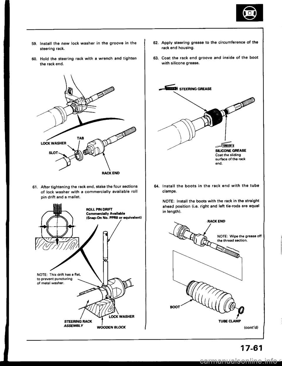
60.
Install the new lock washor in the groov€ in the
steering rack.
Hold the steering rack with I wrsnch and tighten
the rack end.
After tightening th€ rack end, stske the four sections
of lock washer with a commercially available roll
Din drift and a mallet.
ROLL PIN DRIFTComm.rcl.lly Av|il.bl.
lsnrp-On No. PPR8 or .rquiv.lenll
NOTE: This drift has a fl8t,
to prevent puncturing
of motal washer.
ol
62.Apply steering groass to the circumferenc6 of tho
rack end housing.
Coat the rack end groove and inside of the boot
with silicone greas€.
lnstsll the boots in ths rack end with the tube
clamos.
NOTE: Install the boots with the rack in the straight
ahsad position (i.6. right and l€ft tis-rods ar€ squal
in length).
(cont'dl
64.
NOTE: Wipe ths gro.se offthe thread s€ction.
TUEE CLAJTIP
17-61