roll HONDA INTEGRA 1994 4.G User Guide
[x] Cancel search | Manufacturer: HONDA, Model Year: 1994, Model line: INTEGRA, Model: HONDA INTEGRA 1994 4.GPages: 1413, PDF Size: 37.94 MB
Page 346 of 1413
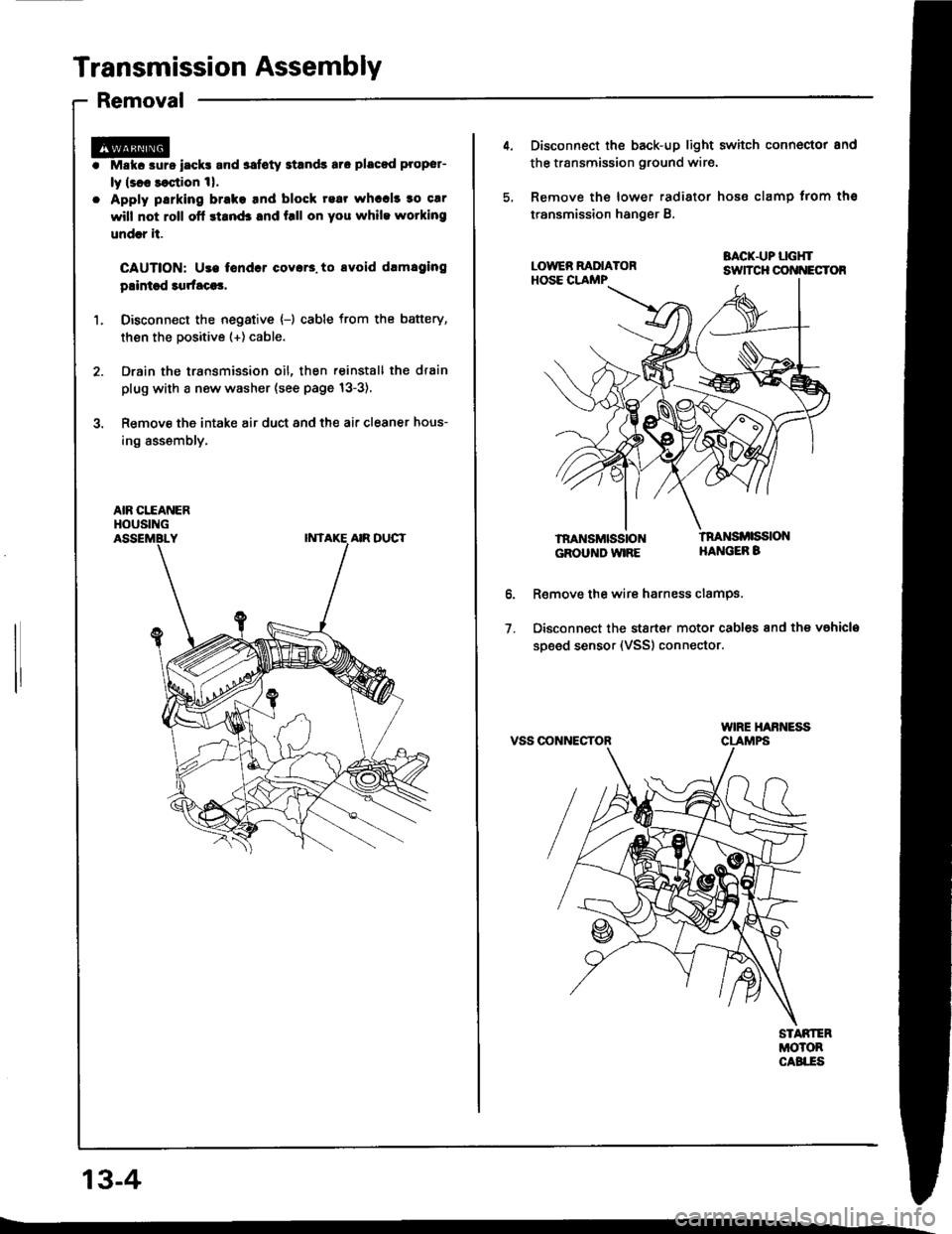
Transmission Assembly
Removal
Mskc aurs iack! and safoty Etands aro placod proper-
ly lsl8 saqtion 1|.
Apply parking brake tnd block rear whccl! to car
will not roll ofl stand3 and f.ll on you while wotking
undrr it.
CAUTION: Use tondcr coyar3. to avoid drmlging
plintsd 3qrfaca3,
Disconn€ct the negative {-) cable from the battery,
then the positive (+) cable.
Drain the transmission oil, then reinstall the drain
plug with a new washer (see page 13-3),
Remove the intake air duct and the air cleaner hous-
ing assembly,
AIR CITANERHOUSING
13-4
4. Disconnect the back-up light switch connoctor and
the transmission ground wir€.
5, Remove the lower radiator hose clamp trom ths
transmission hanger B.
BACK.UP LGHTsuTcH cot{t{EcToR
lnaNsMttistoNGROUND WIRE
tnaNsi ssloNHANGEB B
o.
1.
R€move the wire harness clamPs.
Disconnect the stsrt€r motor cables and the vahicla
soeed sensor (VSS) connector.
VSS OONNECTOR
Page 395 of 1413
The Automatic Transmission is a combination of a 3-e,ement torque convefter and triple-shaft electfonically controlled
automatic transmission which provides 4 speeds forward and 1 speed reverse. The entire unit is positioned in line with
the engine.
Torque Converter, Gears and Clutches
The torque converter consists of a pump, turbine and stator assembly in a single unit, The torque converter is connected
to the engine crankshaft so they turn together as a unit as the engine turns. Around the outside of the torque converter
is a ring gear which meshes with the starter pinion when the engine is being staned. The entire torque converter assem-
bly serves as a flywheel while transmitting power to the transmission mainshaft.
The transmission has three parallel shafts, the mainshaft. countershaft and sub-shaft. The mainshatt is in line with the
engine crankshaft.
The mainshaft includes the clutches for 1 st, and 2ndl4th, and gears for 3rd. 2nd, 4th, reverse and l st (3rd gear is in-
tegral with the mainshaft, while reverse gear is integral with the 4th gear).
The countershaft includes the 3rd clutch and gears Ior 3rd, 2nd,4th, reverse, lst and parking. Reverse and 4th gears
can be locked to the countershaft at its center, providing 4th gear or reverse, depending on which way the selector is moved.
The sub-shaft includes the lst-hold clutch and gears for 1st and 4th
The gears on the mainshait are in constant mesh with those on the countershaft and sub-shaft. When certain combina-
tions of gears in the transmission are engaged by the clutches, power is transmitted from the mainshaft to the counter-
shaft via the sub-shatt to provide @, E, tr. tr and @ position.
Electronic Control
The electronic control system consists of the Transmission Control Module {TCM), sensors, and 4 solenoid valves. Shift-
ing and lock-up are electronically controlled for comfortable driving under all conditions.
The TCM is located below the dashboard, behind the left side kick panel on the driver's side.
Hydraulic Control
The valve bodies include the main valve body, secondary valve body, regulator valve body. servo body, and lock-up valve
body throuqh the respective separator plates.
They are bolted on the torque converter housing.
The main valve body contains the manual valve, 1-2 shift valve, 2-3 shift valve, Clutch Pressure Cont.ol (CPC) valve,
4th exhaust valve, relief valve, and oil pump gears.
The secondary valve body contains the 4-3 kick-down valve,3-2 kick-down valve,2-3 orifice cont.ol valve, 3-4 shitt
valve, orifice control valve. modulator valve, and servo control valve
The regulator valve body contains the pressure regulator valve. lock-up control valve, torque converter check valve, and
cooler check valve.
The servo bodv contains the servo valve which is integrated with the reverse shift fork, throttle valve B, and accumulators.
The lock-ug valve bodv contains the lock-up shift valve and lock-up timing B valve. and is bolted on the secondary valve
body.
Fluid from the regulator passes through the manual valve to the various control valves.
Shitt Control Mochanism
Input to the TCM i.om various sensors located throughout the car determines which shift control solenoid valve should
be activated.
Activating a shift control solenoid valve changes modulator pressure, causing a shift valve to move. This pressurizes
a line to one of the clutches. engaging that clutch and its corresponding gear.
Lock-up Mechanism
In @ position. in 2nd, 3rd and 4th, and E position in 3rd, pressurized tluid can be drained from the back of the tor-
que converter through an oil passage, causing the lock-up piston to be held against the torque converter cover. As this
takes Dlace, the mainshaft rotates at the same speed as the engine crankshatt. Together with hydraulic control, the TCM
optimizes the timing ol the lock-up mechanism.
The lock-up valves control the range of lock-up according to lock-up control solenoid valves A and B, and throttle valve B
When lock-up control solenoid valves A and B activate, modulator pressure changes. Lock-up control solenoid valves
A and B are mounted on the torque converter housing, and are controlled by the TCM.
(cont'd)
14-3
Page 403 of 1413
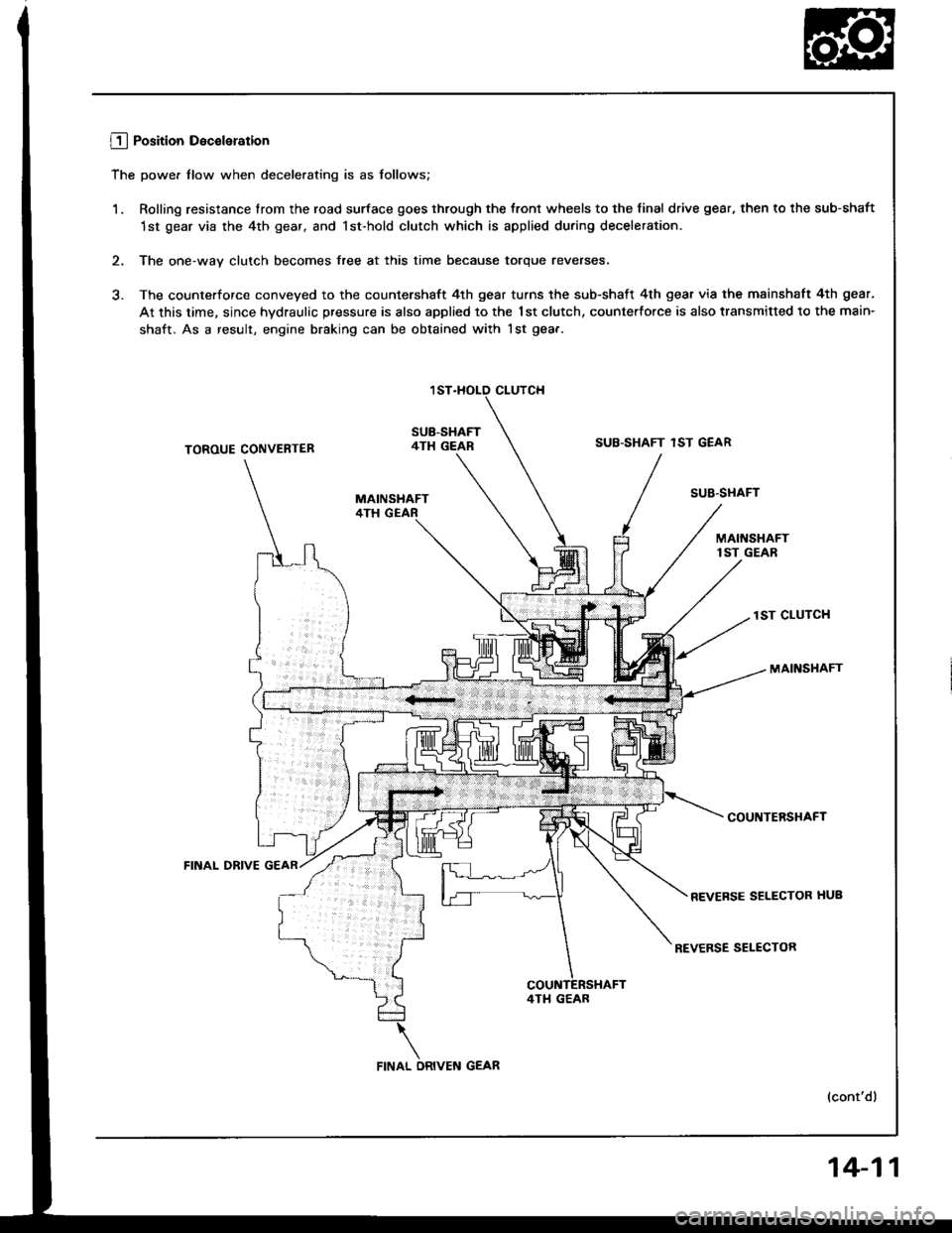
L!_j Position Deceleration
The power tlow when decelerating is as follows;
1. Rolling resistance lrom the road surface goes through the tront wheels to the final drive gear, then to the sub-shaft
1st gear via the 4th gear, and lst-hold clutch which is applied during deceleration.
2. The one-way clutch becomes free at this time because torque reverses.
3. The counterforce conveyed to the countershaft 4th gear turns the sub-shaft 4th gear via the mainshaft 4th gear.
At this time, since hydraulic pressure is also applied to the 1st clutch, counterfo.ce is also transmitted to the main-
shaft. As a result, engine braking can be obtained with lst gea.-
CLUTCH
SUB-SHAFT4TH GEARSUB-SHAFT 1ST GEARTOROUE CONVENTER
FINAL DRIVE
SUB'STIAFT
lST CLUTCH
MAINSHAFT
COUNTERSHAFT
REVEFSE SELECTOR HUB
REVERSE SELECTOR
(cont'dl
4TI1 GEAB
14-11
Page 410 of 1413
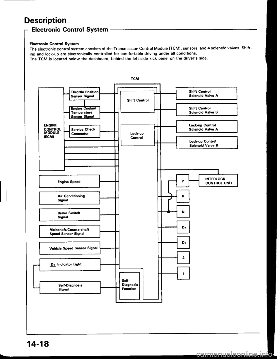
Description
Electronic Control System
Electronic Control System
The electronic control system consists of the Transmission Control Module (TCM), sensors. and 4 solenoid valves. Shift-
ing and lock-up are elect.onically controlled for comfortable driving under all conditions.
The TCM is located below the dashboard, behind the left side kick panel on the driver's side.
Lock-up ControlSolonoid Valvo A
14-18
Page 412 of 1413
Description
Electronic Control System (cont'd)
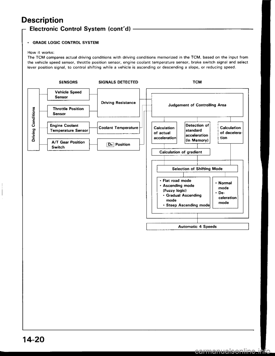
. GRADE LOGIC CONTROL SYSTEM
How it works:
The TCM compares actual driving conditions with driving conditions memorized in the TCM. based on the input trom
the vehicle speed sensor, throttle position sensor, engine coolant temperature sensor, brake switch signal and select
lever position signal, to control shifting while a vehicle is ascending or descending a slope. or reducing speed.
SIGNALS DETECTED
Dliving ResistanceJudgement of Controlling Area
Engine Coolant
TemDerature Sensor
. Flat road mode. Asconding mode
(Fuzzy logic). Gradual Ascending
mode. Steep Ascending
14-20
Page 418 of 1413
Description
Hydraulic Control (cont'dl
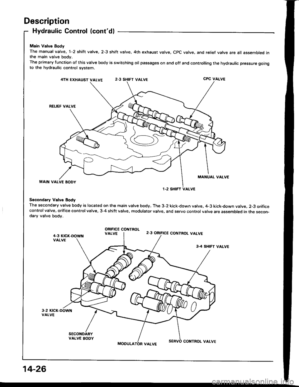
Main Valvo Body
The manual valve, 1-2 shift valve, 2-3 shift valve. 4th exhaust valve. CPC valve, and relief vatve are all assembled inthe main valve body,
The primary function of this valve body is switching oil passages on and off and controlling the hydraulic pressure gotngto the hydraulic control system.
4TH EXHAUST VALVECPC VALVE
RELIEF VALVE
MANUAL VALVEMAIN VALVE BODY
S€condary Vslve Body
The secondary valve body is located on the main valve body. The 3-2 kick-down valve, 4-3 kick-down valve. 2-3 orificecontrolvalve. orifice controlvalve, 3-4 shift valve, modulator valve, and servo control valve are assembled in the secon-da.y valve body.
ORIFICE COIITROLVALVE2-3 ORIFICE CONTBOL VALVE
3.4 SHIFT VALVE
VALVE BODY
MOOULACOITTROL VALVE
1.2 SHIFT VALVE
14-26
Page 421 of 1413
E Position
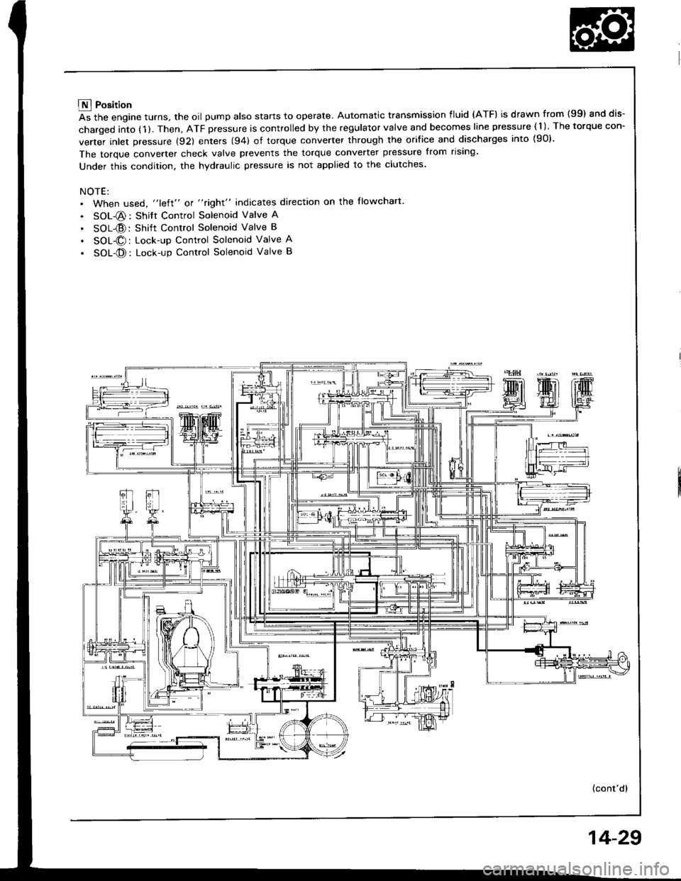
As the engine turns, the oil pump also starts to operate. Automatic transmission fluid (ATF) is drawn from (99) and dis-
charged into (1 ). Then, ATF pressure is controlled by the regulator valve and becomes line pressure ( 1 ). The torque con-
verter inlet pressure (92) enters (94) of torque converter through the orifice and discharges into {90}.
The torque converter check valve prevents the torque converter pressure from rising'
Under this condition, the hydraulic pressure is not applied to the clutches.
NOTE:. When used, "left" or "right" indicates direction on the llowchart
. SOL-@: Shift Control Solenoid Valve A
' SOL{D:Shift Control Solenoid Valve B
. SOL@: Lock-up Control Solenoid Valve A
. SOL-@: Lock-up Control Solenoid Valve B
(cont'd)
14-29
Page 426 of 1413
Description
Hydraulic Flow (cont'd)
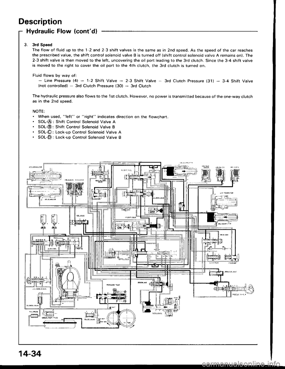
3rd Speed
The tlow of fluid up to the 1-2 and 2 3 shift valves is the same as in 2nd speed. As the speed of the car reaches
the prescribed value, the shift control solenoid valve B is turned off {shilt control solenoid valve A remains on). The
2-3 shift valve is then moved to the left, uncovering the oil port leading to the 3rd clutch. Since the 3-4 shitt valve
is moved to the right to cover the oil port to the 4th clutch, the 3rd clutch is turned on.
Fluid tlows by way of:- Line pressure l4l - 1-2 shift valve - 23 Shift Valve * 3rd ctutch pressure (31) - 3-4 shift valve(not controlled) 3rd Clutch Pressure (3O) - 3rd Clutch
The hydraulic pressure also flows to the l st clutch. However, no power is transmitted because of the one-way clutchas in the 2nd speed.
NOTE:. When used, "lett" o( " tight" indicates direction on the flowcharl.. SOL-@: Shift Control Solenoid Valve A. SOL-@:Shift Control Solenoid Valve B. SOL-O: Lock-up Control Solenoid Valve A. SOL-@: Lock-up Control Solenoid Valve B
14-34
Page 431 of 1413
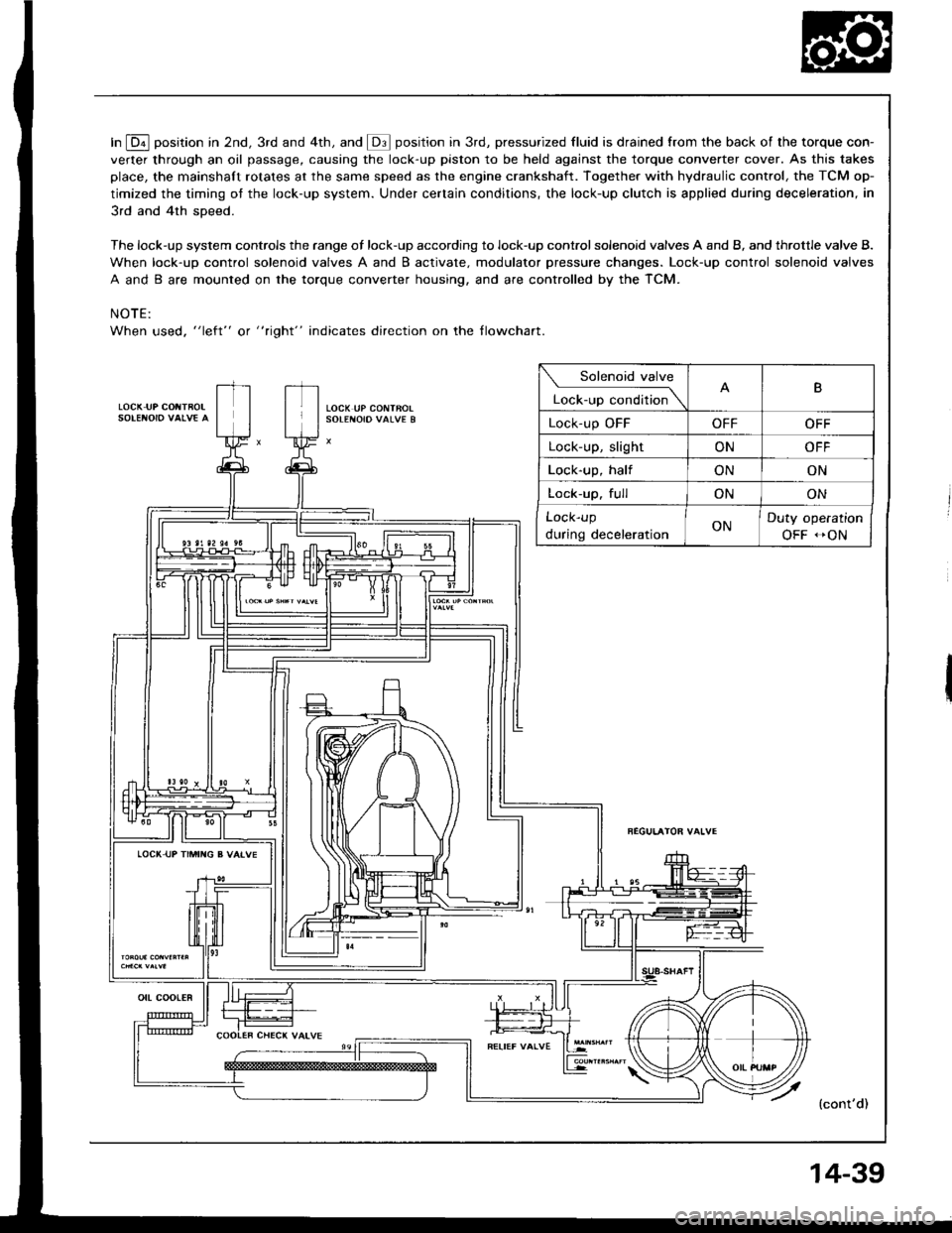
In E position in 2nd, 3rd and 4th, and @ position in 3rd, pressurized fluid is drained from the back of the torque con-
verter through an oil passage, causing the lock-up piston to be held against the torque converter cover. As this takes
place, the mainshaft rotates at the same speed as the engine crankshaft. Together with hydraulic control, the TCM op-
timized the timing ot the lock-up system. Under certain conditions, the lock-up clutch is applied during deceleration, in
3rd and 4th sDeed.
The lock-up system controls the range of lock-up according to lock-up control solenoid valves A and B, and throttle valve B.
When lock-up control solenoid valves A and B activate. modulator pressure changes. Lock-up control solenoid valves
A and B are mounted on the torque converter housing, and are controlled by the TCM.
NOTE:
When used, "left" or " tight" indicates direction on the tlowchart.
LOCK IJP COIITBOL
Solenoid valve
L""f."p "."aiti""\B
Lock-up OFFOFFOFF
Lock-up, slightONOFF
Lock-up, halfONON
Lock-up. fullONON
Lock-up
during decelerationONDuty operation
OFF -ON
LOCI( UP TIMII{G B VAIVE
{cont'd)
ott coot€R
14-39
Page 478 of 1413
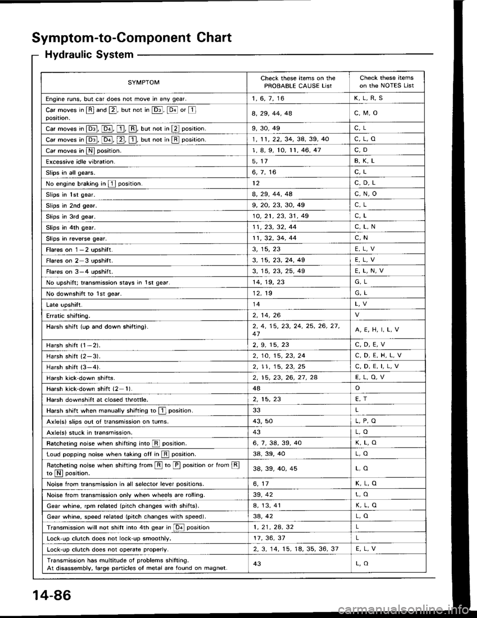
Symptom-to-Component Chart
Hydraulic System
SYMPTOMCheck these items on the
PROBABLE CAUSE ListCheck these items
on the NOTES List
Engine runs, but car does not move in any gear.1, 6, 7, 16K,L,R,S
Car moves in @ and @, but not in @, @ or Iposataon.a, 29, 44. 4ac,M,o
Car moves in E, @, [, @, uut not in E position.9,30,49C, L
car moves in p:1, [o-il, [2-], [!, uut not in E position.1, 11, 22, 34, 38, 39, 40c,L,o
Car moves in N position.1, 8, 9, 10, 11,46,47C,D
Excessive idle vibration.5, 1'1B,K,L
Slips in all gears.6, 7, 16C,L
No engine braking in E position.12C,D,L
Slips in 1st gear.8, 29, 44, 4Ac,N,o
Slips in 2nd gear.9, 20, 23, 30, 49C, L
Slips in 3rd gear.10, 21 , 23, 31 , 49C,L
Slips in 4th gear.11, 23, 32, 44C,L,N
Slips in reverse gear.11,32,34,44C,N
Flares on 1-2 upshilt.3, 15, 23E,L,V
Flareson2 3 upshilt.3, 15, 23, 24, 49E,L,V
Flares on 3-4 upshift.3, 15, 23, 25, 49E,L,N,V
No upshift; transmission stays in 1st gear.14,19,G, L
No downshift to lst gear.12. 19G, L
Late upshift.14
Erratic shitting.2, 14,26
Harsh shift (up and down shiftingl.2, 4, 15, 23, 24, 25, 26, 27,
47A,E, H, I, L,V
Harsh shitt {1-2).2, 9. 15, 23C,D,E,V
Harshshilt (2-3).2, 10, 15, 23, 24C,D,E,H,L,V
Harsh shift (3-4).2,| 1, 15, 23, 25C, D, E, I,L,V
Harsh kick'down shifts.2, 15, 23, 26, 27. 2AE,L,O,V
Harsh kick-down shift 12 1)48o
Harsh downshift at closed throttle.2, 15, 23FT
Harsh shift when manually shifting to E] position.33L
Axle{s} slips out of transmission on turns.43,50
Axlels) stuck in transmission.43L,O
Ratcheting noise when shifting inro E position.6,7,38,39,40K,L,O
Loud popping noise when taking ott in E position.3a,39,40L,O
Ratcheting noise when shifting from E to E position or from Eto N I oosition.38,33,40,45L,O
Noise from transmission in all selector lever positions.6, 11K,L,O
Noise trom transmission only when wheels are rolling.39, 42L,O
Gear whine, rpm related (pitch changes with shitts).a, 13, 41K,L,O
Gear whine, speed rel6ted (pitch changes with speed).38, 42L,O
Transmission will not shift into 4th gear in @ position1,21,24.32L
Lock-up clutch does not lock-up smoothly.17, 36, 37L
Lock-up clutch does not operate properlV.2.3. 14, 15. 18, 35, 36, 37E,L,V
Transmission has multitude of problems shitting.
At disassembly, large particles oI metal are found on magnet.43L,O
14-86