section 23 HONDA INTEGRA 1994 4.G Owner's Manual
[x] Cancel search | Manufacturer: HONDA, Model Year: 1994, Model line: INTEGRA, Model: HONDA INTEGRA 1994 4.GPages: 1413, PDF Size: 37.94 MB
Page 78 of 1413
Gylinder Head
Removal
I
t
Engine removal is not required for this procedure.
CAUTION: To avoid damaging tho cylinder head, wait
until tho ongino coolant temporature drops bolow 100"F
{38"C) beforo loo36ning the rotainin0 bolts.
NOTE:
. Inspect the timing belt before removing the cylinder
neao.
. Turn the crankshaft pulley so that the No. 1 piston is
at top dead center (TDCI (page 6-12).
. Mark all emissions hoses before disconnecting them.. Anti-theft radios have a coded theft protection circuit.
Be sure to get the customer's code number before.- Disconnecting the battery.- Removing the No. 32 (7.5 A) fuse irom the under-
hood fuse/relay box.- Removing the radio.
After service, reconnect oower to the radio and turn it
on.
When the word "CODE" is displayed, enter the cus-
tomer's 5-digit code to restore radio operation.
1. Disconnect the negative terminalfrom the battery.
2. Drain the engine coolant (see page 10-5).
. Remove the radiator cap to speed draining.
3. Relieve fuel pressure (see Section 1 1).
@ Do not smoke whils working on tusl
systom, keep opon flame or spark away trom work
area. Drain fuol only inlo an approvod containsr.
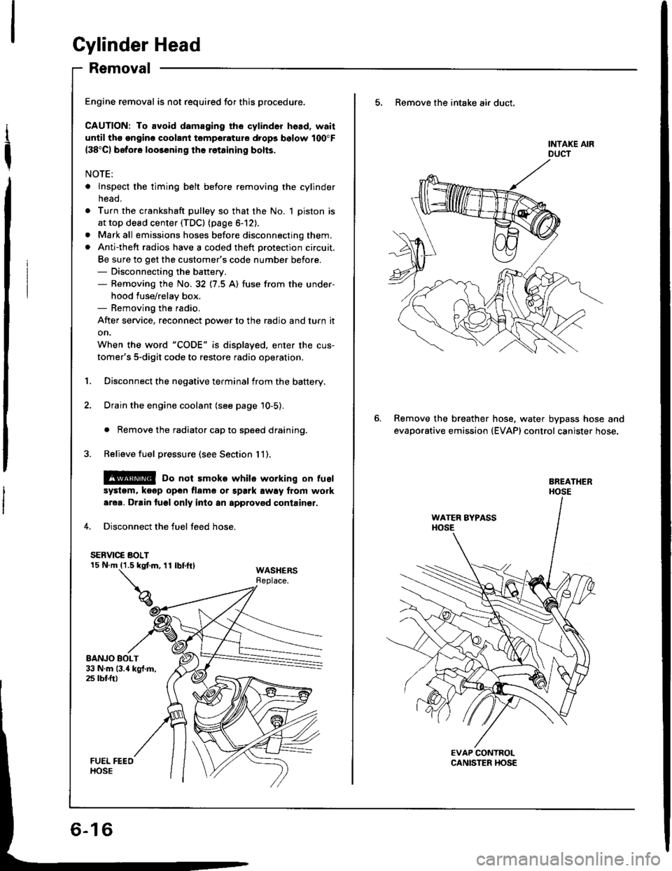
4. Disconnect the fuel feed hose.
SERVIC€ BOLT
WASHERSReplace.
5, Remove the intake air duct.
Remove the breather
evaporative emission
hose, water bypass hose and(EVAP) control canister hose.
Page 79 of 1413
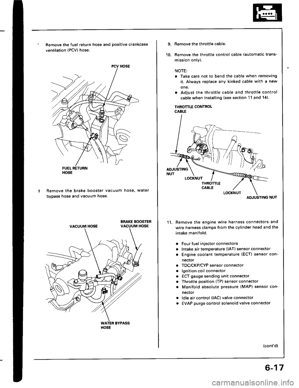
Remove the fuel return hose and positive crankcase
ventilation (PCV) hose.
Remove the brake booster vacuum hose, water
bypass hose and vacuum hose.
ERAKE BOOSTERVACUUM HOSE
HOSE
VACUUM HOSE
HOSE
9.
10.
Remove the throttle cable.
Remove the throttle control cable (automatic trans-
mission only).
NOTE:
. Take care not to bend the cable when removing
it. Always replace any kinked cable with a new
one.
. Adjust the throttle cable and throttle control
cable when installing (see section 11 and 14).
THROTTLE CONTROLCABLE
Remove the engine wire harness connectors and
wire harness clamps trom the cylinder head and the
intake manifold.
Four fuel injector connectors
Intake air temperature (lAT) sensor connector
Engine coolant temperature (ECT) sensor con-
necror
TDC/CKP/CYP sensor connector
lgnition coil connector
ECT gauge sending unit connector
Throttle position (TP) sensor connector
Manifold absolute Dressure (MAP) sensor con-
nector
ldle air control (lAC) valve connector
EVAP purge control solenoid valve connector
11.
a
a
a
a
a
a
a
a
a
(cont'dl
ATI'USTING
6-17
Page 87 of 1413
I
Replacement
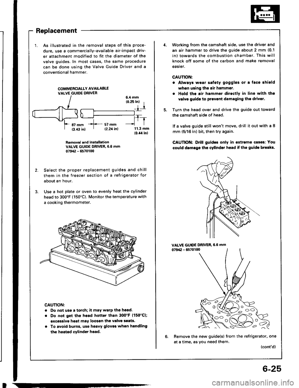
1. As illustrated in the removal steps of this proce-
dure, use a commercially-available air-impact driv-
er attachment modified to fit the diameter of the
valve guides. In most cases. tho same procedure
can be done using the Valve Guide Driver and a
conventional hammer.
COMMERCIALLY AVAILABI,I
VALVE GUIDE DRIVER
RGmov.l rnd In3tlllationVALVE GUIDE DRIVER, 6.6 mm
0?942 - 6570100
Select the proper replacement guides and chill
them in the freezer section of a refrigerator for
about an hour.
Use a hot plate or oven to evenly heat the cylinder
head to 300'F (150'Cl. Monitor the temperature with
a cooking thermometer.
CAUTION:
. Do not use a torch; it may warP the hgad.
. Do not get ths head hottq than 3OO'F 1150"C);
excessive hgat may loos€n thG valvs soat3.
. To avoid burns, usa hoavy glov93 whon handling
the heated cylinder hoad.
-----T_-
lrl
11.3 mmlo.il,l in)
f sz --| 12.21i^l
6-25
4.Working from the camshaft side. use the driver and
an air hammer to drive the guide about 2 mm {0.1
in) towards the combustion chamber. This will
knock oft some of the carbon and make removal
eaSrer.
GAUTIOiI:
o Alwrys woar safety goggles or a face shiold
wh6n using tho Eir hammer.
. Hold ths air hammsr directly in lins with the
vrlvr guidc to prsvont damaging tho drivor.
Turn the head over and drive the guide out towatd
the camshaft side of head.
lf a valve guide still won't move, drill it out with a 8
mm (5/16 in) bit, then try again.
CAUTION: Drill guid$ only in oxtremo cases: You
could drmrgo tho cylinder hosd if ths guido br"akr.
VALVE GUIDE DRIVER,6.6 mm
07942 - 65701q)
Remove the new guide{s} from the refrigerator, one
at a time, as you need them.
{cont'd)
OO ",
O (V /rl -1-- ) o
Page 113 of 1413
Timing Belt
Installation (cont'dl
1Loosen and retighten the adjusting bolt to tsnsion
thB belt.
Rotate the crankshaft about 4 or 6 turns countsr-
clockwise so that the belt positions on the pulleys.
Adjust ths timing bolt tension (see pags &48).
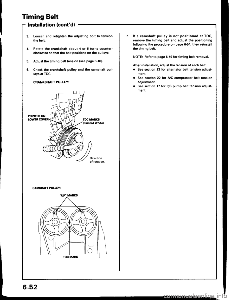
Ch€ck ths crankshaft pullsy and the camshaft pul-
lsys at TDC.
CRANKSHAFT PULLEY:
1.lf a camshaft pulley is not positioned at TDC.
.emove the timing belt and adiust the positioning
following the procedure on page 6-51, th6n r6install
rhe riming belt.
NOTE: Refsr to page 6,19 for timing b€lt removal.
Aft€r installation, adiust the tension of each b€lt.
o See section 23 for alternator belt tension adiust-
menr.
. See section 22 tot NC compr€ssor b6lt tension
adjustm€nt.
. See section 17 for P/S pump b6lt t€nsion adiust-
menL
4.
5.
b.
CAMSHAFT PULI..EY:
"UP- MANKS
6-52
Page 116 of 1413
Cylinder Head
Removal
Engine removal is not required or this procedure.
CAUTION: To avoid damaging tho cylinder head, wail
u[tilths.nginc coolant tsmperaturo drops bolow 100"F(38'Cl bafore loos6ning tho retaining bolts.
NOTE;
. Inspect the timing belt before removing the cylinder
head.
Turn the crankshaft pulley so that the No. 1 piston is
at top dead center (TDc) {page 6-51).
Mark all emissions hoses betore disconnecting them.
Anti-theft radios have a coded theft protection circuit.
Be sure to get the customer's code number before- Disconnecting the battery.- Removing the No.32 (7.5 A) fuse trom the under-
hood fuse/relay box.- Removing the radio.
After service, reconnect power to the radio 8nd turn it
on.
When the word "CODE" is displaved. enter the cus-
tomer's 5-digit code to restore radio operation,
Disconnect the negative terminal from the battery.
Drain the engine coolant (see page 10-5).
. Remove the radiator cap to speed draining.
Relieve fuel pressure (see section 111.
l@ Do not 3moke whilo working on fuel
a
a
'1.
systgm. ko6p opon tlamo ot Spark away trom work
aroa. Drain fugl only into an approved containsr,
4. Disconnect the fuel feed hose.
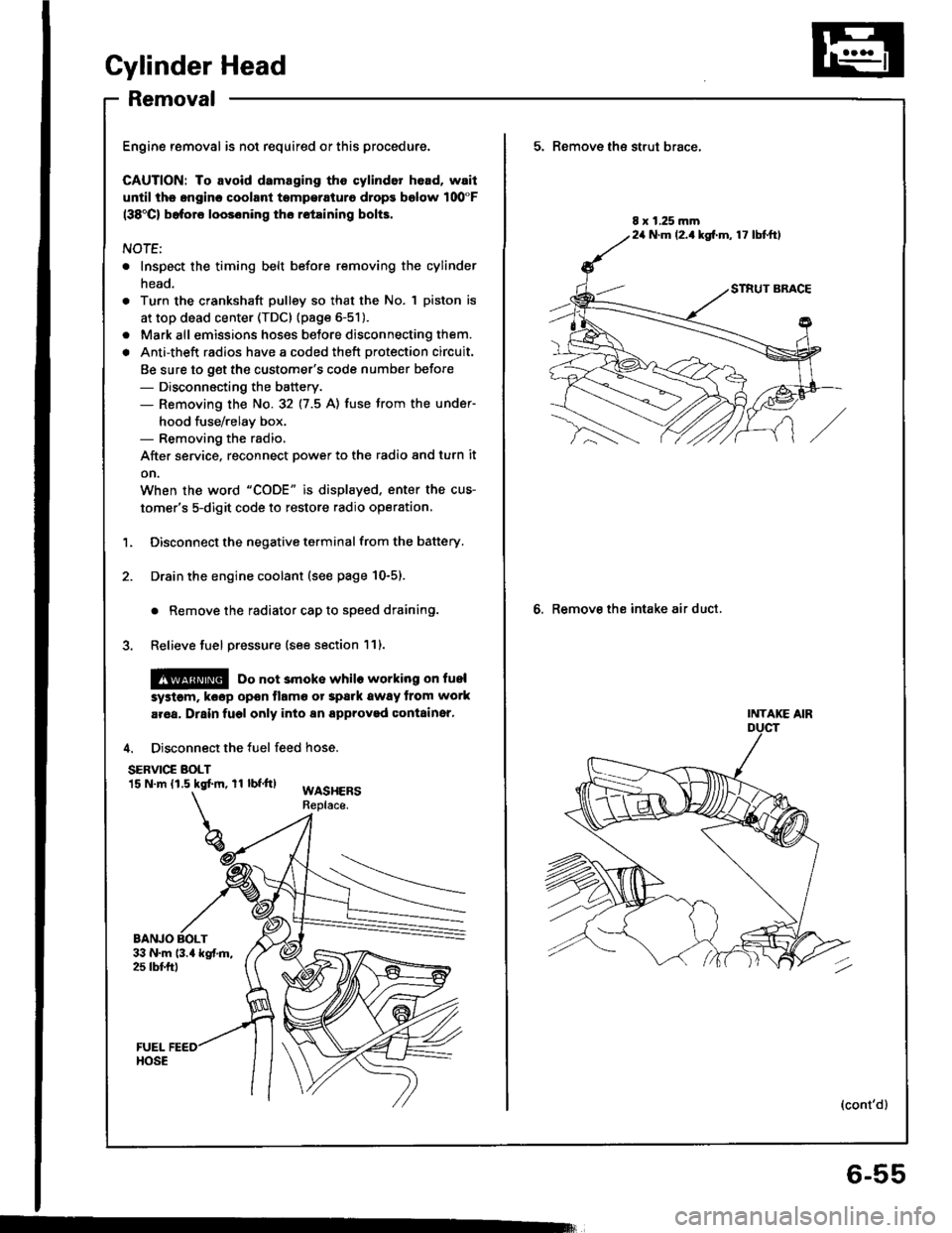
SERVIC€ BOLT15 N.m (1.5 kgtm, rl bf.tt)WASHERSReplace.
BANJO BOLT
5. Remove th€ strut brace,
6. Remove the intake air duct.
8 x 1.25 mm24 N.m (2.1kg[.m, 17 lbtftl
INTAKE AIR
(cont'd)
6-55
Page 132 of 1413
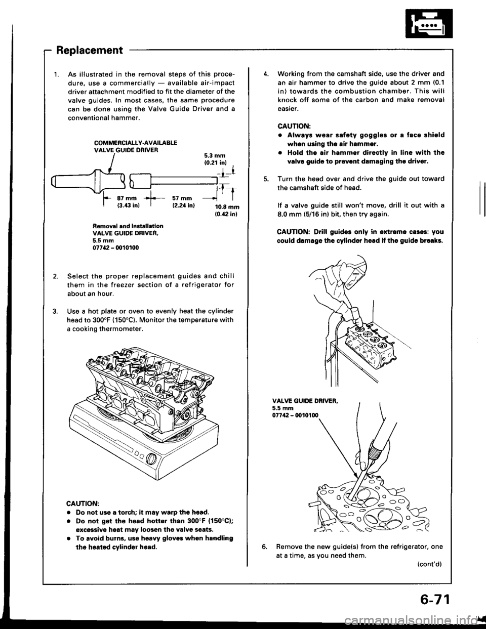
1.As illustrated in the removal steps ot this proce-
dure. use a commercially - available air-impact
driver attachment modified to fit the diameter of the
valve guides. In most cases, the same procedure
can be done using the Valve Guide Driver and a
conventional hammer,
COMMCRCIALLY.AVAILABLEVALVE GUIDE DRIVER
az mm +- sz mm{3.43 inl I tz.zt in)
tfr
10.8 mm10.42 inl
5.3 mm(0.21 inl I
_{l
R.mov.l and In3trll.tionVALVE GUIDE DRIVER.5.5 mm07742 - q)101tt0
Select the proper replacement guides and chill
them in the freezer section of a refrigerator for
about an hour.
Use a hot plate or oven to evenly heat the cylinder
head to 300'F (150"c). Monitor the temperature with
a cooking thermometer.
CAUTION:
. Do not us9 a iorch; it may warp ths hsad.
. Do not get ths head hottor than 300"F (150"C);
excsssivo hgat may loogen the valvo soaG.
. To avoid burns, use hsaw glovo3 whon handling
the heated cylindor h€ad.
Working from the camshaft side, use the driver and
an air hammer to drive the guide about 2 mm (0.1
in) towards the combustion chamber. This will
knock off some of the carbon and make removal
easier.
CAUTION:
. Always wear ssfcty gogglos 01 a taca rhiold
whcn using thc air hrmmcr,
. Hold tho.ir hammer diroctly in line with tho
v6lvo goido to prov.nt drmaging tho driv6r.
Turn the head over and drive the guide out toward
the camshaft side of head.
lf a valve guide still won't move, drill it out with a
8.0 mm (5/16 in) bit, then try again.
CAUTION; Drill guid6 only in oxtromc cs3os: you
could dlmsgo tho cylinder hoad if tho guidc brcakr.
VALVE GUIDE DBIVER.5.5 mm07742 - 0010100
6.Remove the new guide(s) from the refrigerator, one
at a time, as vou need them.(cont'd)
l o -_ -\
i oc)
Page 156 of 1413
Piston
lnstallation
'1.
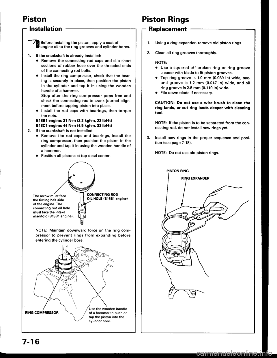
Before installing the piston, apply a coat ofengine oil to the ring grooves and cylinder bores.
lf the crankshaft is already installed:
. Remove the connecting rod caps and slip short
sections of rubber hose ove. the threaded ends
of the connecting rod bolts.
a Install the ring compressor, check that the bear'
ing is securely in place, then position the piston
in the cylinder and tap it in using the wooden
handle of a hammer.
Stop after the ring compressor pops free and
check the connecting rod-to-crank journal align-
ment before tapping piston into place.
. Install the rod caps with bearings, then torque
the nuts,
81881 ongino: 31 N.m {3.2 kgf.m, 23 lbf.ftl
818C1 cngino: 44 N'm 1,t.5 kgf.m, 33 lbf.ftl
lf the crankshaft is not installed:
o Remove the rod caps and bearings. install the
ring compressor, then position the piston in the
cylinder and tap it in using the wooden handle of
a nammer.
. Position all Distons at toD dead center.
CONNECTING RODOIL HOI-E (Br8Bl onginelThe arrow must facethe timing belt sideof the engine. Theconnecting rod oil holemust lace the intak€manifold {81881 €ngine).
NOTE: Maintain downward force on the ring com-
pressor to prevent rings from expanding before
entering the cylinder bore,
BING COMPRESSORUse the wooden handleof a hammer to push ortap the piston into thecylinder bore.
Piston Rings
Replacement
1.Using a ring expander, remove old piston rings.
Clean all ring g.ooves thoroughly.
NOTE:
. Use a squared-oJf broken ring or ring groove
cleaner with blade to fit piston grooves.
. Top ring groove is 1.0 mm (0.039 in) wide, sec-
ond groove is 1.2 mm (0.047 in) wide. and oil
ring groove is 2.8 mm (0.110 in) wide.. File down blade if necessary.
CAUTION: Do not use a wire brush to cloan thr
ring lands, or cut ring lands dsopo. with cl€aning
tool.
NOTE: lf the piston is to be separated from the con-
necting rod, do not install new rings yet.
Install new rings in the prope. sequence and posi-
tion (see page 7-18).
NOTE: Do not use old piston rings.
Page 283 of 1413
ldle Control System
Fast ldle Thermo Valve
DEscliptlon
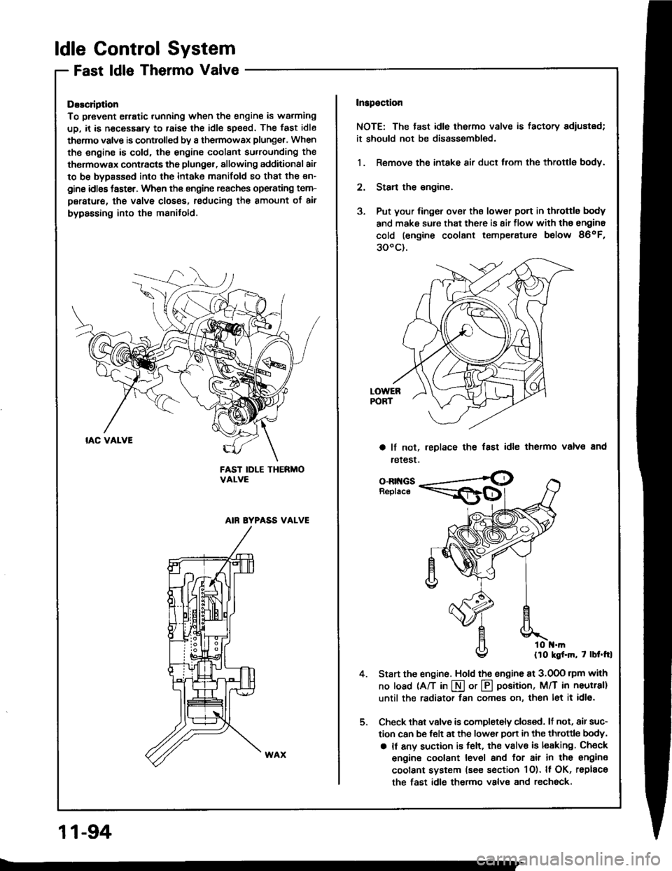
To prevent erratic running when the engine is warming
up, it is n€cessary to raise the idle speed. The fast idle
thermo valve is controlled by a thermowax plunger, When
the engine is cold. the engine coolant su.rounding the
thermowax contracts the plunger, allowing additional air
to be bypassed into the intake manifold so that the en-
gine idlss taster. When the engine reaches operating tem-
peratur€, the valve closss, reducing the amount of air
bypassing into the manifold.
FAST IDLE THERMOVALVE
AIN EYPASS VALVE
Inspaction
NOTE: The tast idle thermo valve is factory adiustsd;
it should not be disassombl€d.
1. Remove the intake air duct from the throttlg body.
2. Stan the engine.
3. Put your finger over ths lower port in throttle body
and make sure that there is 8ir flow with tho engine
cold (engine coolant temperatute below 86oF,
300c).
a lf not,
retest.
leplace the fast idle thermo valvs and
4.
o-Rr{GsReplace
llo kgf.m, 7 lbt.trl
Start the engine. Hold the sngine at 3.0OO rpm with
no load (A/T in I or @ position, M/T in neutral]
until the radiator fan comes on, then let it idl6.
Check thst valve is completely closed. lt not, air suc-
tion can be telt at the lower Don in the throttle body,
a It any suction is felt, the valve is leaking Check
engine coolant level and for air in tho engine
coolant system (see section 1O). ll OK, rsplace
the fast idle thermo valve and rechock.
11-94
Page 284 of 1413
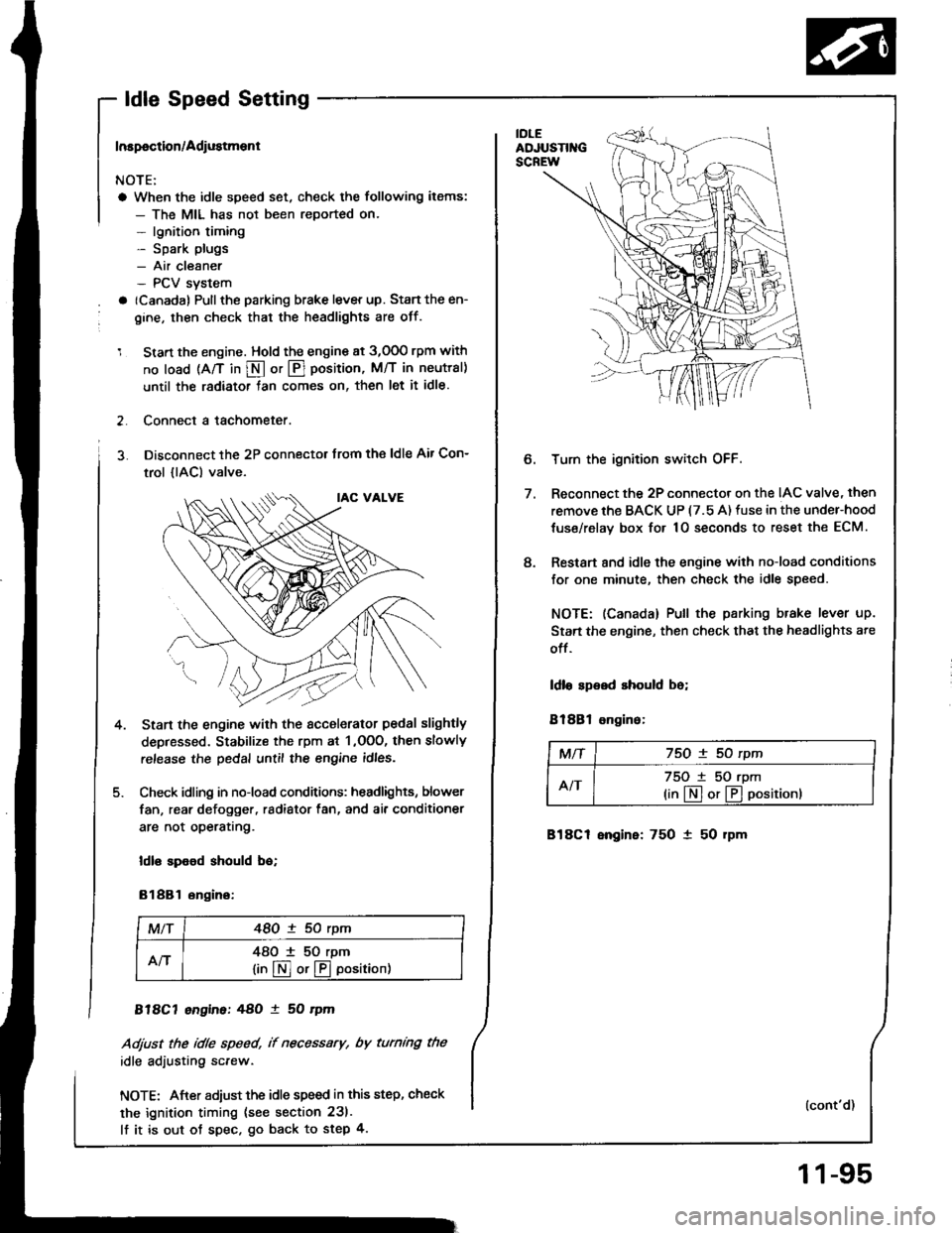
- ldle Speed Setting
Inspoction/Adiustment
NOTE:
a When the idle speed set, check the following items:
- The MIL has not been reported on.- lgnition timing- Spark plugs- Air cleaner- PCV svstem
a (Canada) Pullthe parking brake lever up. Stan the en-
gine, then check that the headlights are off.
1 Start the engine. Hold the engine at 3,000 rpm with
no load (A/T in S or @ position, M/T in neutral)
until the radiator tan comes on, then let it idle.
2. Connect a tachometer.
3. Disconnect the 2P connectot trom the ldle Air Con-
trol {lAC) valve.
Start the engine with the sccelerator pedal slightly
depressed. Stabilize the rpm at 1 ,OOO, then slowly
release the pedal until the engine idles.
Check idling in no-load conditions: headlights, blower
fan, rear defogger, radiator fan, and ai. conditioner
are not operatrng.
ldl€ spood should bo;
81881 ongino:
MlT48O ! 50 rym
An48O I 50 rpm
lin@or@oosition)
818C7 engine:48O ! 50 rym
Adjust the idle speed, if necessary, by turnmg the
idle adiusting screw.
NOTE: After adiust the idle speed in this step, check
the ignition timing (see section 231.
lf it is out ot spec. go back to step 4.
4.
e
Turn the ignition switch OFF.
Reconnect the 2P connector on the IAC valve, then
remove the BACK UP (7.5 A) fuse in the under-hood
tuse/relav box for 1O seconds to reset the ECM.
Restart 8nd idle the engine with no-load conditions
for one minute, then check the idle speed.
NOTE: (Canada) Pull the parking brake lever up.
Start the engine, then check that the headlights ate
off.
ldlo speed should be;
81881 ongino:
MTf75O ! 50 rpm
AIT75O t 50 rpm
(in[]or@positionl
818C1 engine: 750 1 50 rpm
(cont'd)
11-95
Page 298 of 1413
[":::,::-'
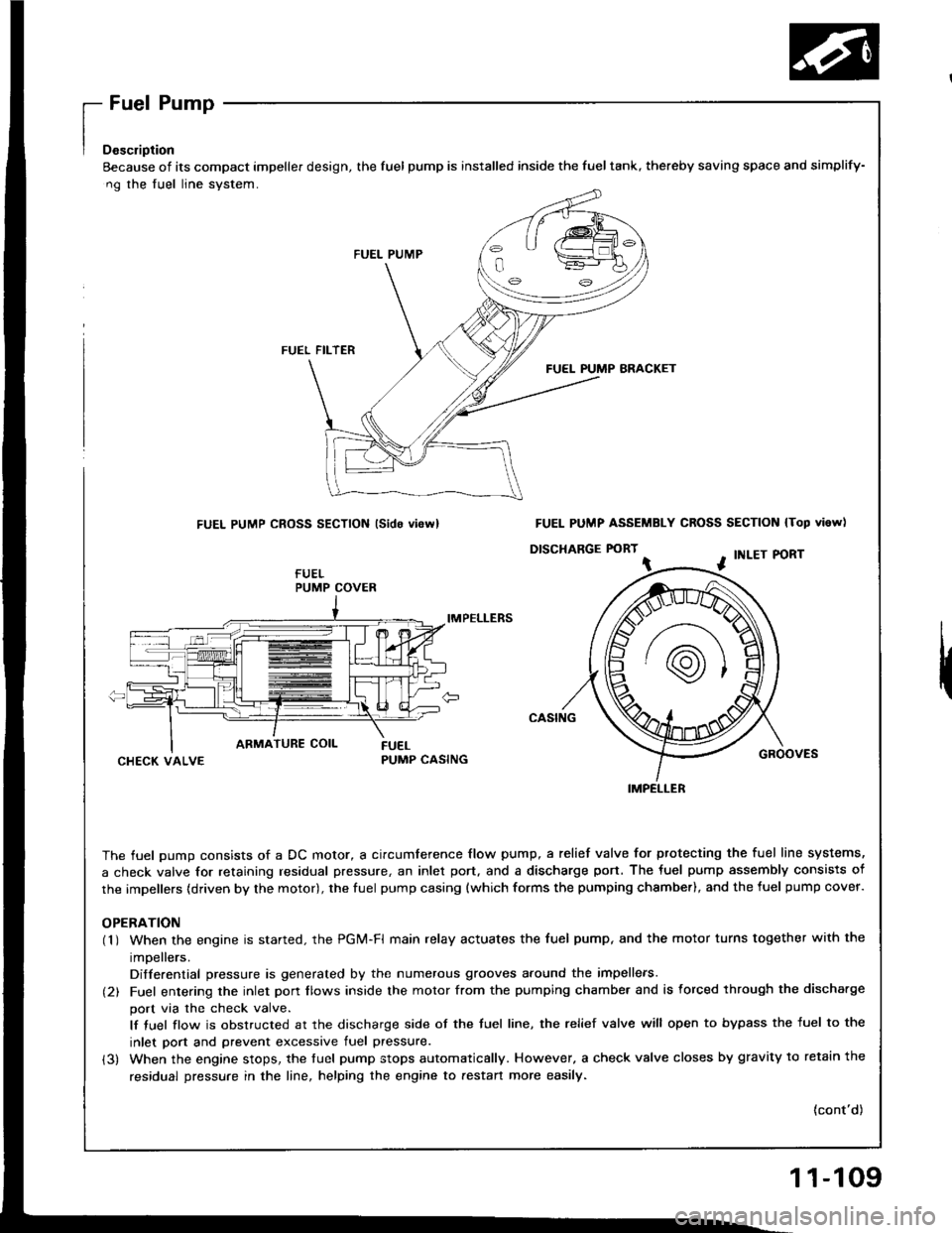
Eecause of its compact impeller design, the fuel pump is installed inside the fueltank, thereby saving space
ng the fuel line system.
FUEL PUMP
FUEL FILTER
FUEL PUMP BRACKET
FUEL PUMP CROSS SECTION lsido vi6rvl
IMPELLERS
CHECK VALVEPUMP CASING
The fuel oumo consists of a DC motor, a circumference flow pump, a relief valve for ptotecting the fuel lir
a check valve for retaining residual pressure, an inlet port, and a discharge port. The fuel pump assembly
the impellers (driven by the motor), the fuel pump casing {which forms the pumping chsmber), and the fuel p
OPERATION(1 ) When the engine is started. the PGi/t-Fl main relay actuates the fuel pump, and the motor turns togeth
impellers.
Differential pressure is generated by the numerous grooves around the impellers.
(2) Fuel entering the inlet porr flows inside the motor from the pumping chambe. and is forced through th
port via the check valve.
lf tuel flow is obstructed at the discharge side of the tuel line, the relief valve will open to bypass the
inlet port and prevent excessive fuel pressure.
(3) When the engine stops, the tuel pump stops automatically. However, a check valve closes by gravity t
residual pressure in the line, helping the engine to aestan more easily.
and simplify-
N lTop vi6w)
PORT
GROOVES
fuel line systems,
embly consists of
fuel pump cover.
together with the
rgh the discha.ge
ss the fuel to the
avitv to retain the
(cont'd)
PUMP COVER
FUEL PUMP ASSEMBLY CROSS SECTION
D|SCHARGE FORT ^ . tNLEr P
IMPELLER
11-109