section 23 HONDA INTEGRA 1994 4.G Repair Manual
[x] Cancel search | Manufacturer: HONDA, Model Year: 1994, Model line: INTEGRA, Model: HONDA INTEGRA 1994 4.GPages: 1413, PDF Size: 37.94 MB
Page 507 of 1413
Valve Caps
Description
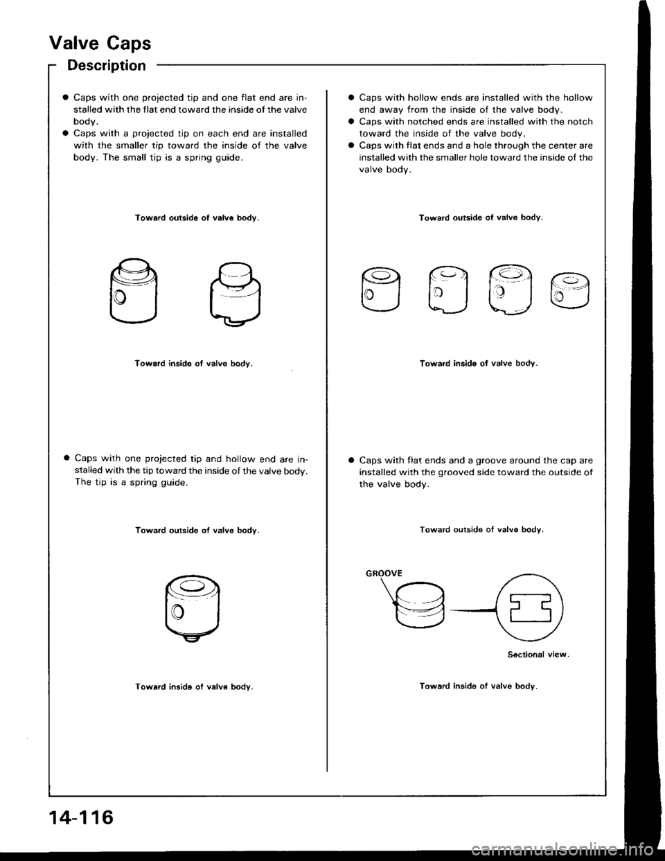
Caps with one projected tip and one flat end are in-
stalled with the llat end toward the inside ot the valve
body.
Caps with a projected tip on each end are installed
with the smaller tip toward the inside of the valve
body. The small tip is a spring guide.
Caps with hollow ends are installed with the hollow
end away from the inside of the valve body.
Caps with notched ends are installed with the notch
toward the inside of the valve body.
Caps with flat ends and a hole through the center are
installed with the smaller hole toward the inside of the
valve body.
Toward outside ot valv6 bodv.Toward outside oI valv€ bodv.
rq fq1 @.
lrj taj u
Toward inside of valve body.Towa.d inside of valve body.
Caps with one projected tip and hollow end are in-stalled with the tip toward the inside of the valve body.The tip is a spring guide.
Caps with llat ends and a groove around the cap are
installed with the grooved side toward the outside of
the valve body.
Towa.d outside ot valve body.Toward outside of valve bodv.
Toward inside of valve body.
Sectional view
Toward inside of valve body.
14-116
Page 556 of 1413
Transmission
Installation {cont'd)
14.
15.
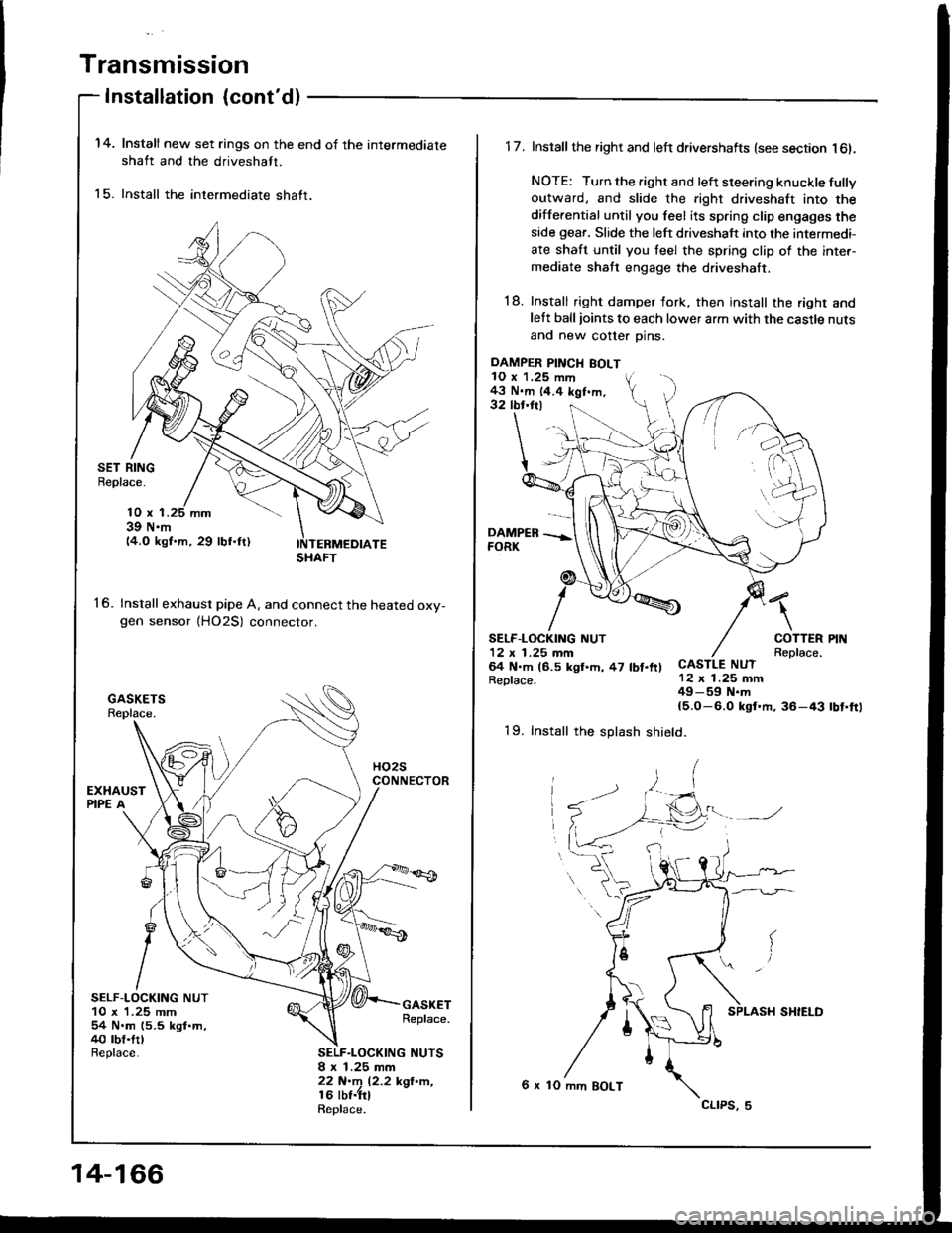
Install new set rings on the end of the intermediate
shaft and the driveshaft.
Install the intermediate shaft.
SET RINGBeplace.
16.
10 x 139 N.m14.O kgf.m, 29 lbf.ftl
Install exhaust pipe A. and connect the heated oxv-gen sensor {HO2S) connector.
SELF-LOCKING NUT10 x 1.25 mm54 N.m (5.5 kgl.m,40 rbt.trlReplace.
GASKETReplace.
SELF.LOCKING NUTSI x 1.25 mm22 N.m 12.2 kgl'n,16 lbt.trlRepl6ce.
SHAFT
14-166
DAMPER PINCH BOLT10 x 1.25 mm43 N.m 14.4 kgf.m,32 tbr.ftl
1 7. Install the right and left drivershafts (see section l6l.
NOTE: Turn the right and left steering knuckle fullyoutward, and slide the right driveshaft into the
differential until you feel its spring clip engages theside geaf. Slide the left driveshaft into the intermedi-
ate shaft until you teel the spring clip of the inter-mediate shaft engage the driveshaft.
18. Install right damper fork, then install the right andlett balljoints to each lower arm with the castle nuts
and new cotter Dins.
\
COTTERReplace.CASTLE NUT12 x 1.25 mm49-59 N.m{5.O-6.0 ksf.m, 36-43
SELF.LOCKING NUT12 x 1 .25 mm64 N.m (6.5 kgl.h, 47 lbt.ftlReplace.
rbt'ft1
19. Install the splash shield.
6 x 10 mm BOLT
cltPs, 5
Page 557 of 1413
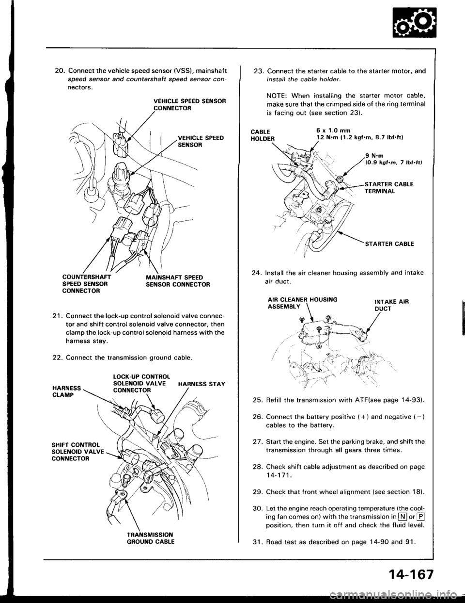
20. Connect the vehicle speed sensor (VSS), mainshatt
speed sensor and counterchalt speed sensor con
nectors.
VEHICLE SPEED SEiISORCONNECTOR
21. Connect the lock-uD control solenoid valve connec-
tor and shift control solenoid valve connector. then
clamp the lock-up control solenoid harness with the
harness stay.
22. Connect the transmission ground cable.
LOCK-UP CONTROLSOLENOID VALVE HARNESS STAY
23. Connect the starter cable to the starter motor, and
install the cable holder.
NOTE: When installing the starter motor cable,
make sure that the crimped side of the ring terminal
is facing out (see section 23).
CABLEHOLDER
6x 1.0 mm'12 N.m (1.2 kgf'm,8.7 lbt.tl)
24.
N.mlO.9 ksr.m, 7 tbr-rtt
STARTER CAELE
Install the air cleaner housing assembly and intake
arr oucl.
AIR CLEANER HOUSINGASSEMBLYINTAKE AIRDUCT
25.
26.
24.
29.
30.
Retill the transmission with ATF(see page '14-93).
Connect the battery positive ( + ) and negative ( - )
cables to the battery.
Start the engine. Set the parking brake, and shift the
transmission through all gears three times.
Check shitr cable adjustment as described on page
14-171 .
Check that front wheel alignment (see section 18).
Let the engine reach operating temperature (the cool-
ing tan comes on) with the transmission in S or @position, then turn it off and check the fluid level.
31. Road test as described on page 14-9o and 91.
14-167
Page 560 of 1413
shift cable
Removal/lnstallation
a All SRS electrical wiring hamosses are covor€d withyellow insulation.
a Before disconnecting any pan ot th€ SRS wire har-noss, connect the short connectorc (soe page 23-7O1.a Roplace th€ entiro attect€d SRS haness assembly itit has an open circuit ot damaged wi.ing.
@@[ uar" sul€ litts are placed proparty {so6
section 1).
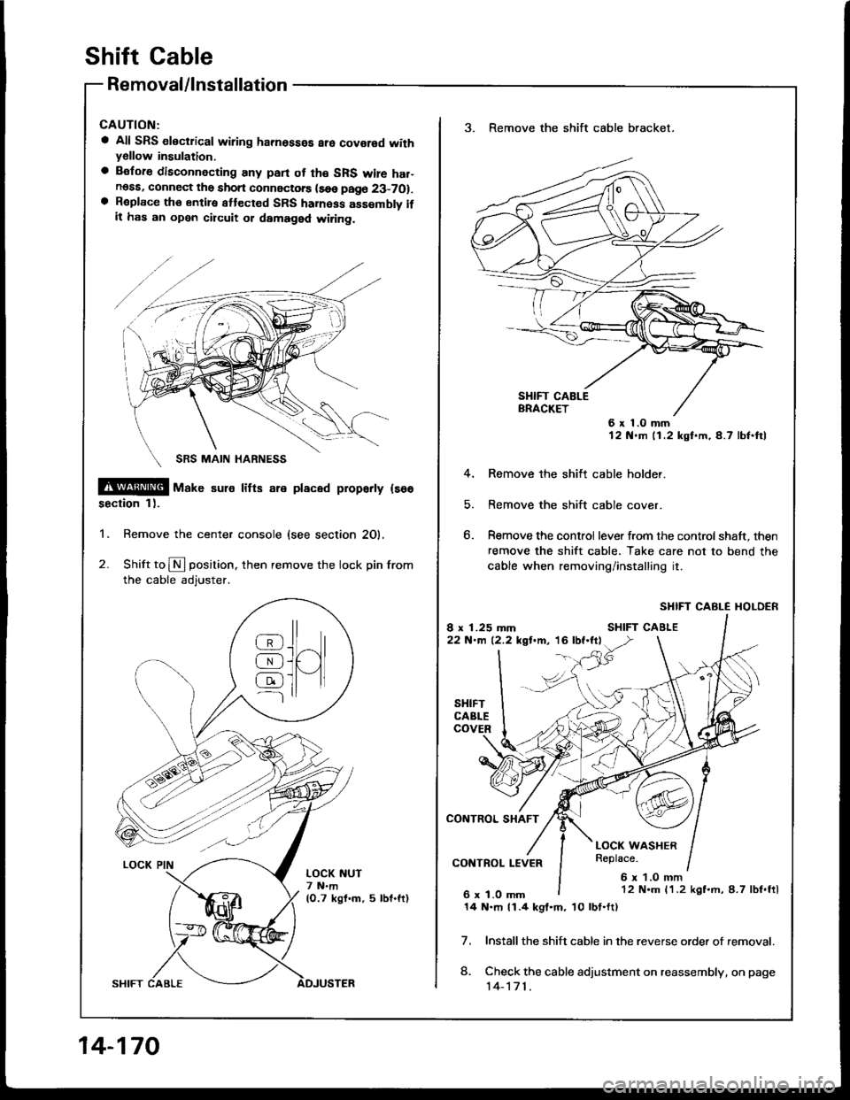
1. Remove the center console {see section 20).
2. Shift to N position. then remove the lock pin from
the cable adjuster.
@J^ll
AJUI[qJ ]l tl---l
LOCK NUT7 N.m(O.7 kgf.m, 5 lbf.ft)
14-170
3. Remove the shift cable bracket.
6x1.0mm12 N.m 11.2 kgf.m,4.7 lbf.ftl
4. Remove the shitt cable holder.
5. Remove the shift cable cover.
6. Remove the control lever from the control shaft, then
remove the shift cable. Take care not to bend the
cable when removing/installing it.
SHIFT CABLE I{OLDER
Install the shift cable in the reverse orde. of removal.
Check the cable adjustment on reassembly, on page
14-171.
7.
8.
12 N.m 11.2 kgf.rh, 8.7 lbf.ftl
14 N.m 11.4 kgl.m, 10lbt.ft)
Page 561 of 1413
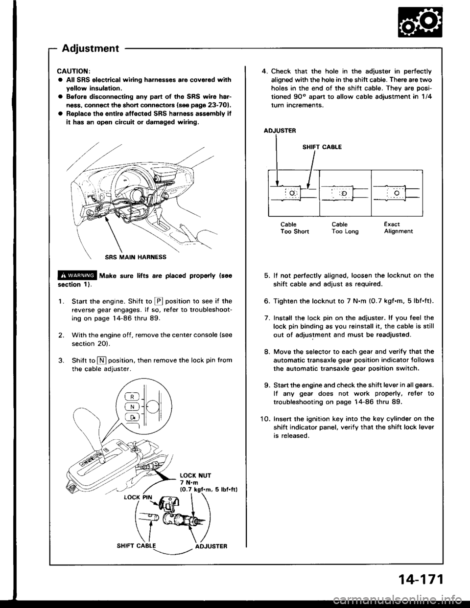
4. Check that the hole in the adiuste. in perfectly
aligned with the hole in the shift cable. There are two
holes in the end of the shitt cable, They are posi-
tioned 9Oo apart to allow cable adiustment in 1/4
lurn Incremenls.
ADJUSTER
CableI oo snonCableToo LongExactAlignment
5. It not perfectly aligned, loosen the locknut on the
shift cable and adjust as required.
6. Tighten the locknut to 7 N.m (O.7 kgf.m, 5lbf.ft).
7. Install the lock pin on the adiuster. lf you feel the
lock pin binding as you reinstall it, the cable is still
out of adjustment and must be readjusted.
8. Move the selector to each gear and verify that the
automatic transaxle gear position indicator tollows
the automatic transaxle gear position switch.
9. Start the engine and check the shift lever in all gea.s.
lf any gea. does not work properly, refer to
troubleshooting on page 14-86 thru 89.
1O. lnsert the ignition key into the key cylinder on the
shift indicator panel, ve.ify that the shift lock lever
is released,
CAUTION:
a All SRS electrical widng harn€sses are covar€d with
yollow insulation.
a Before disconnecting any part of ths SRS wire har-
ness, connect the shon connectors (see page 23-701.
a R€place the entire affected SRS halnass asssmbly it
it has an op€n circuit or damaged wiring.
@ tu"t" sure lifts a.e placed properly ls66
ssction 1).
Start the engine. Stritt to @ position to see if the
reverse gear engages. lf so, refer to troubleshoot-
ing on page 14-86 thru 89.
Wilh the engine off, remove the center console {see
section 20).
Shilt to N position. then remove the lock pin from
the cable adjuster.
'1.
/
''fidlfr
I
t+@
\/ \
CABLE-.'.-_--l../ADJUSTER
]H
@
@
@
Adjustment
14-171
Page 562 of 1413
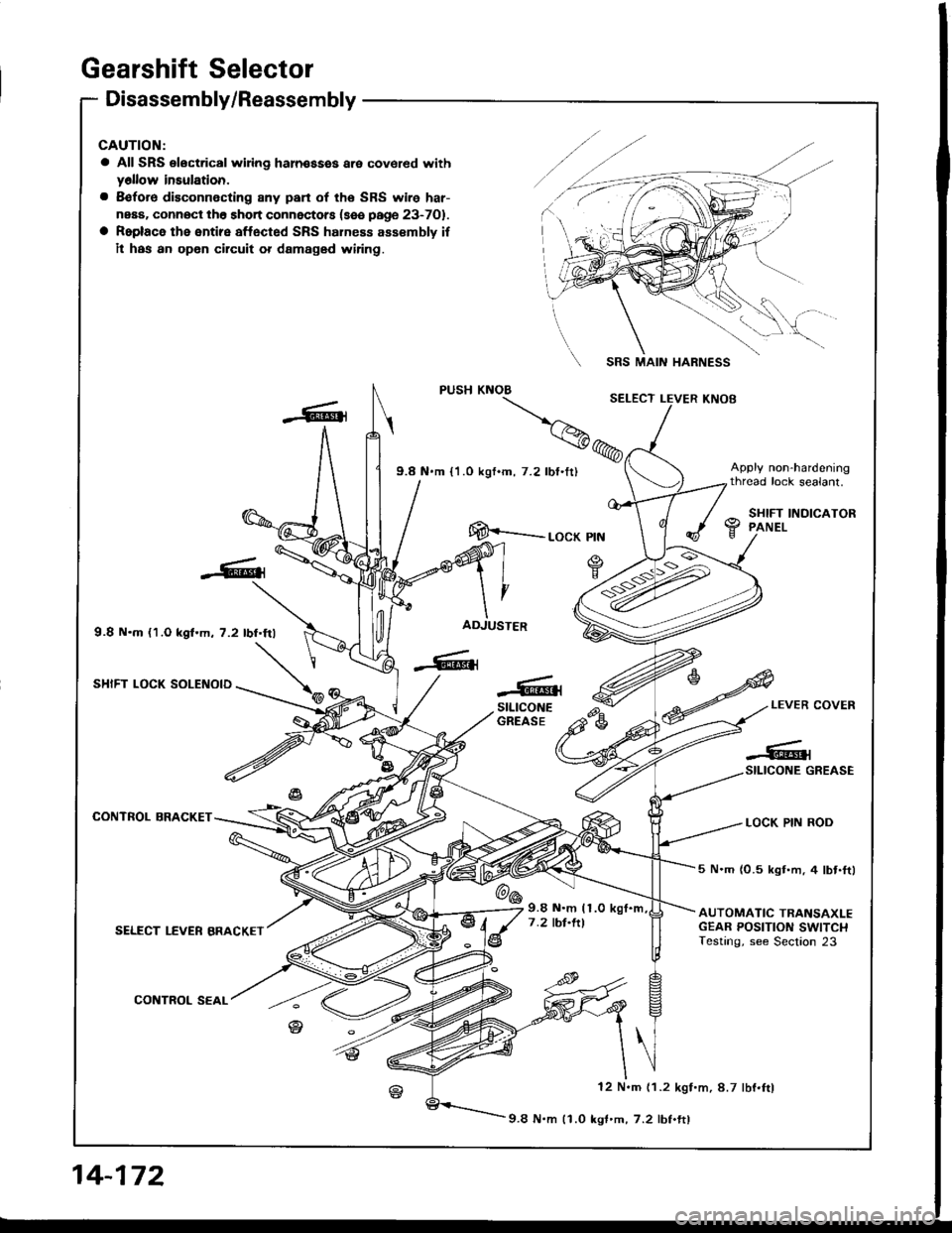
Gearshift Selector
Disassembly/Reassembly
CAUTION:
a All SRS electrical wiing haln€ssss are covered withy6llow insulation.
a 8€fore disconnecting 8ny pan of the SRS wire har-
neaa. connOct th6 short connectors (sse page 23-701.
a Roplace the entire affected SRS hahess assembly if
il has an opon circuit or damaged wiring.
9.8 N.m {1.O kgf.m, 7.2 lbf.frl
SHIFT LOCK SOLENOID
CONTROL BRACKET
SELECT LEVER BRACKET
CONTROL SEAL
SRS MAIN HARNESS
[E--__ rocK ptN
ADJUSTER
-6{stLtcoNEGREASEe-LEVER COVER
LOCK PIN ROD
-#qSILICONE GREASE
@6
5 N.m (0.5 kgt.m, 4 lbt.ftl
AUTOMATIC TRANSAXLEGEAR POSITION SWITCHTesting, see Section 23
9.8 N.m (1.0
7 .2 tbt.ltl
12 N.m (1.2 kgf.m, 8.7 lbf.ftl
9.8 N.m 11.0 kgf'm,7.2 lbf.ftl
14-172
Page 564 of 1413
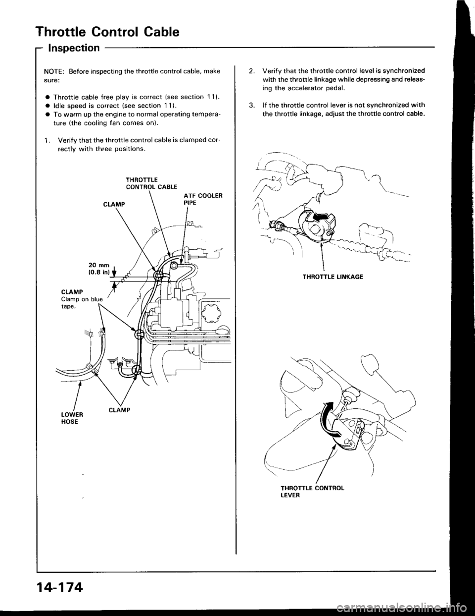
Throttle Control Cable
Inspection
NOTE: Betore inspecting the throttle control cable, make
sure:
a Throttle cable free play is correct (see section 1 1).
a ldle speed is correct (see section 1l).
a To warm up the engine to normal operating tempera-
ture {the cooling fan cor'res on)
1 . Verify that the throttle control cable is clamped cor-
rectly with three positions.
14-174
Verify that the throttle control level is synchronized
with the thronle linkage while depressing and releas-
ing the accelerator pedal.
lf the throttle control lever is not synchronized with
the throttle linkage. adjust the throttle control cable.
\
,r:
Page 566 of 1413
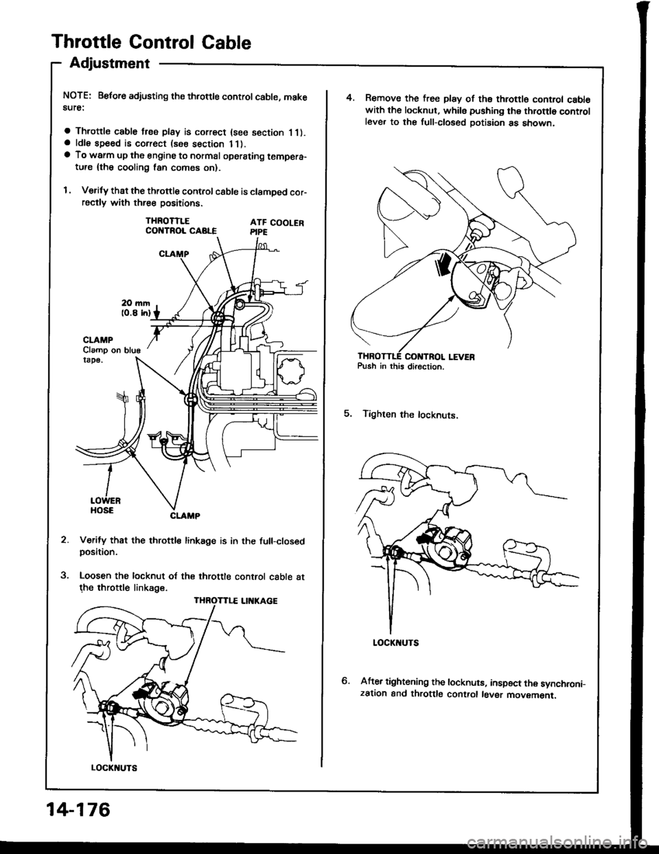
Throttle Control Cable
Adjustment
NOTE: Before adjusting ths throttle control cable, makesute:
a Throttle cable free play is correct {see section 11).a ldle speed is correct (see section 11).a To warm up the engine to normal oporsting tempera-ture {the cooling lan comes on}.
I . Verify that the throttle control c8ble is clamDed cor-rsctly with three positions.
THROTTLECOI{TROL CABLEATF COOLERPIPE
5.
CLAMP
Verify that the throttle linkage is in the full-closedposition.
Loosen the locknut of the throttle control cable atthe throttle linkage.
Clamp on blu6
THROTTLE LII{KAGE
LOCKI{UTS
14-176
4. Remove the free play of ths throttl6 control cabl€with the locknut, whils pushing thg throttlo controlleve. to the full-closed Dotision as snown,
5. Tighten the locknuts.
After tightening the locknuts, inspect the synchroni-zation and throttlg control l6ver movemenr.
Page 573 of 1413
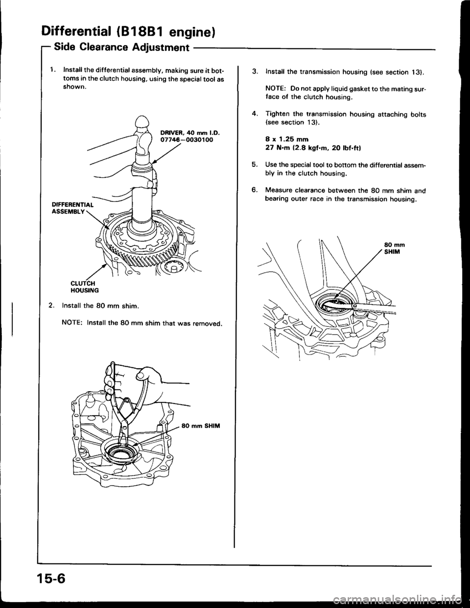
Differential (81 881 engine)
Side Clearance Adjustment
l. Install the diflerential assembly, making sure it bot-toms in the clutch housing. using the specialtoolasshown.
2. Install the 80 mm shim.
NOTE: Instsll the 80 mm shim that was removed.
mm SHIM
HOUSING
15-6
?Install the transmission housing (see section 13).
NOTE: Do not apply liquid gasket to the mating sur-,ace ot the clutch housing.
Tighten the transmission housing attaching bolts(see section 13).
8 x 1.25 mm
27 N.m 12.8 kgf'm, 20 lbf.ftl
Use the special tool to bonom the differential assem-bly in rhe clutch housing.
Measure clearance between the 80 mm shim andbearing outer race in the transmission housing.
4.
tt.
Page 574 of 1413
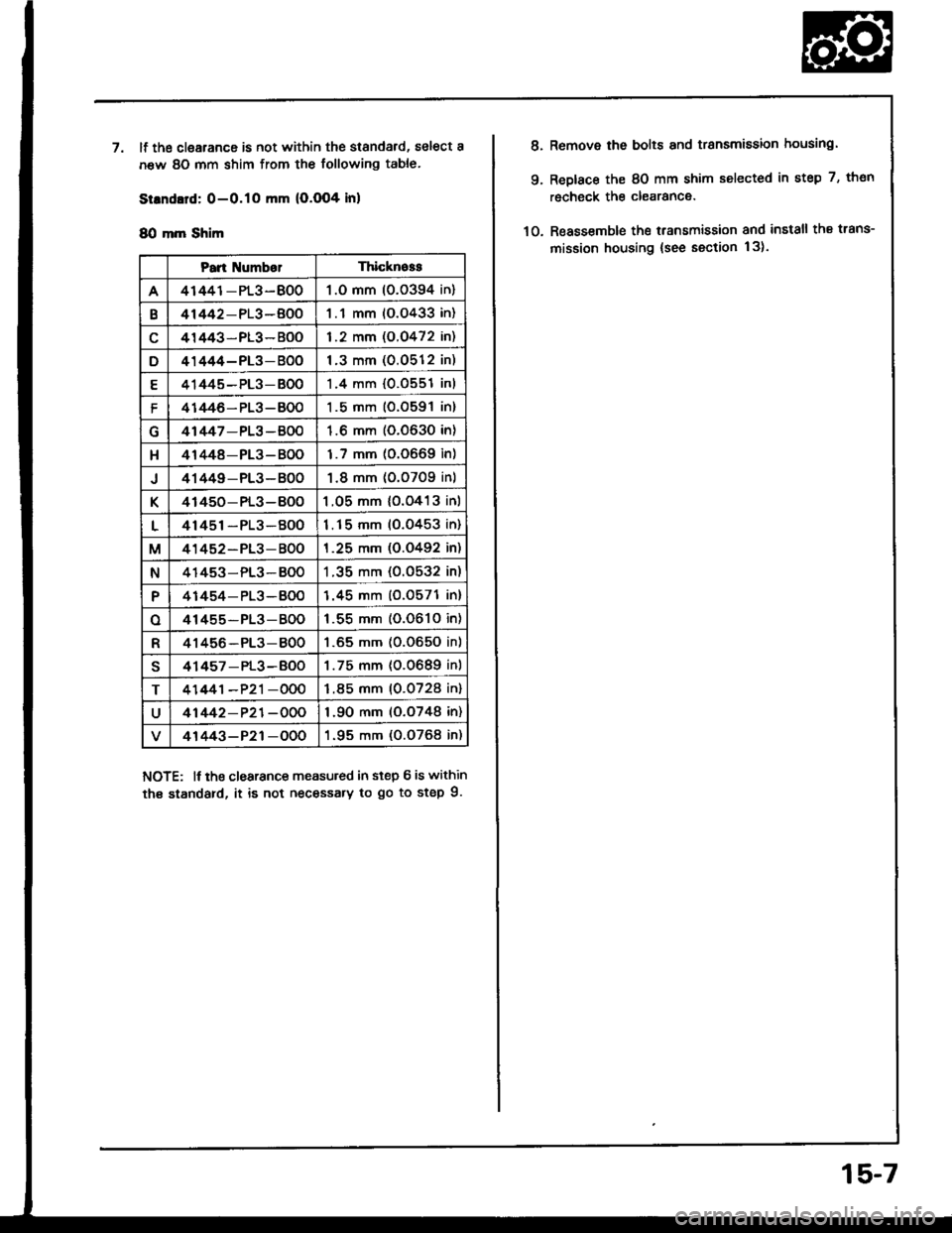
'llf the clearance is not within the standard, select a
new 80 mm shim from the following table.
Strndard: 0-O.1O mm (O.O04 inl
8O mm Shim
NOTE: lf tho clearance measuled in step 6 is within
th€ standard, it is not necessary to go to step 9.
Pan NumberThicknoss
A41441-PL3-BO01.O mm 10.0394 in)
B41442-PL3-BOO1.1 mm (O.O433 in)
41443-PL3- BOO1.2 mm (O.O472 in)
D41444-PL3-BOO1.3 mm (0.0512 in)
E41445-PL3-BO01.4 mm {0.0551 inl
f41446- PL3-BO01.5 mm (O.O591 in)
41447-PL3 -BOO1.6 mm (0.0630 in)
H41448-PL3- B001.7 mm (0.0669 in)
J41449-PL3- BO01.8 mm (0.0709 inl
K41450- PL3-BOO1.05 mm {o.o413 inl
L41451-PL3-BOO1.15 mm (0.0453 in)
M41452-PL3-BOO1.25 mm (O.O492 in)
N41453-PL3-BO01 .35 mm (0.0532 in)
P41454-PL3-BOO1.45 mm (0.0571 in)
o41455-PL3-BOO1 .55 mm (0.061O in)
R41456-PL3-8001.65 mm (0.O650 in)
s41457 - PL3-BOO1.75 mm (0.0689 in)
T41441-P21-OOO1.85 mm (0.0728 in)
U41442-P21-OOO1.90 mm (o.o748 in)
41443-P21-OOO1.95 mm (0.O768 in)
8.
9.
Remove the bolts and transmission housing.
Replace the 8O mm shim selected in step 7, thon
recheck the clearance.
Reassemble the transmission and install the trans-
mission housing {see section 13).10.
15-7