section 23 HONDA INTEGRA 1994 4.G Repair Manual
[x] Cancel search | Manufacturer: HONDA, Model Year: 1994, Model line: INTEGRA, Model: HONDA INTEGRA 1994 4.GPages: 1413, PDF Size: 37.94 MB
Page 583 of 1413
Differential (B18C1 enginel
Tapered Roller Bearing Preload Adjustment (cont'dl
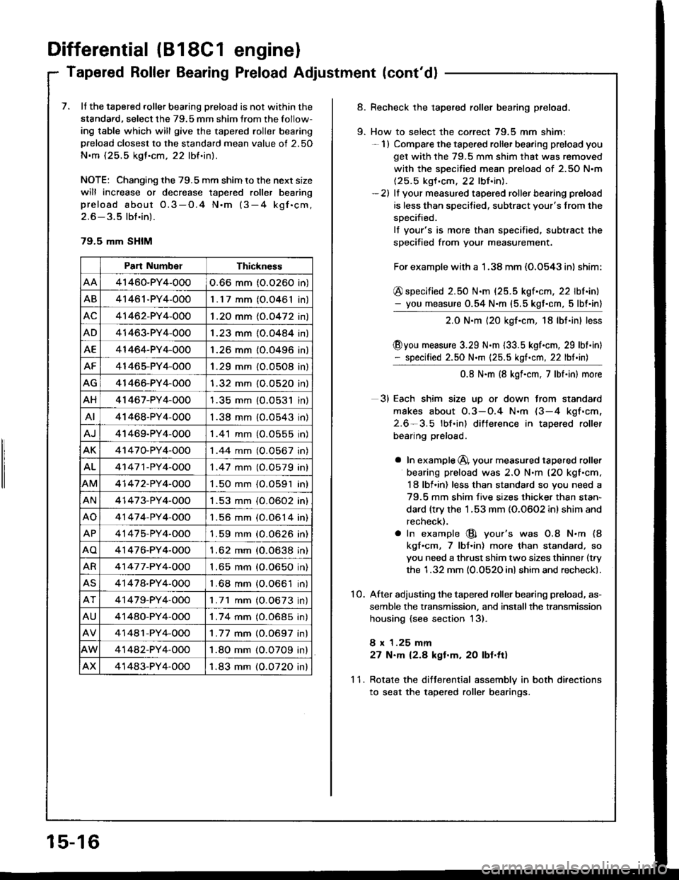
7. It the tapered roller bearing preload is not within the
standard, select the 79.5 mm shim lrom the follow-
ing table which will give the tapered roller bea.ing
preload closest to the standard mean value of 2.50
N.m (25.5 kgJ.cm, 22 lbf.in).
NOTE: Changing the 79.5 mm shim to the next size
will increase or decrease tapered roller bearing
preload about O.3-O.4 N.m (3-4 kgf.cm,
2.6 - 3.5 lbt.in).
79.5 mm SHIM
Part NumbelThickness
41460-PY4-0000.66 mm (0.0260 in)
AB41461-PY4-0001.17 mm (O.0461In,
AC41462-PY4-0001 .2O mm (0.0472 in)
AD41463-PY4-0001.23 mm (O.O484 in)
AE41464-PY4-0001.26 mm (0.0496 in)
AF41465-PY4-OOO1.29 mm (O.O5O8 in)
AG41466-PY4-OOO1.32 mm (O.O52O in)
AH41 467-PY4-0001.35 mm {O.O531 in)
AI41468-PY4-0001.38 mm (O.O543 in)
AJ41469-PY4-0001 .41 mm (O.0555 in)
AK41470-PY4-OOO1 .44 mm (0.0567 in)
AL41 47 1 -PY 4-OOO1 .47 mm (0.0579 in)
AM41 47 2-PY 4-OOO1.50 mm {O.O591 in)
AN41473-PY4-0001 .53 mm (0.0602 in)
AO41 47 4-PY 4-OOO1.56 mm (0.0614 in)
AP41475-PY4-OOO'l .59 mm (O.0626 in)
AO4'1476-PY4-O001.62 mm (0.0638 in)
AR41 47 7 -PY 4-OOO1 .65 mm (0.0650 in)
AS41478-PY4-0001 .68 mm {0.0661 in)
41479-PY4-OOO1.71 mm (O.0673 in)
AU41480-PY4-OOO1.74 mm (0.0685 in)
41481-PY4-OOO1 .77 mm {0.0697 in}
41442-PY4-OOO1.80 mm (O.O7O9 in)
AX41483-PY4-OOO1.83 mm (0.0720 inl
15-16
9.
Recheck the tapered roller bearing preload.
How to select the correct 79.5 mm shim:- 1) Compare the tapered roller bearing preload you
get with the 79.5 mm shim that was removed
with the specified mean preload of 2.50 N.m(25.5 kgf .cm. 22 lbf.inl.-2) lf your measured tapered roller bearing preload
is less than specified, subtract your's from the
soecified.
lf your's is more than specified, subtract the
specified from your measurement.
For example with a 1 .38 mm (O.O543 in) shim:
@ specified 2.50 N.m (25.5 kgf.cm, 22 lbf.in)- you measure 0.54 N.m (5.5 kgt.cm, 5lbt'in)
2.0 N.m {20 kgf.cm, 18lbt.in} less
@you measure 3.29 N.m {33.5 kgl.cm, 29 lbl.in)- specified 2.50 N.m {25.5 kgf.cm, 22 lbf.in)
0.8 N.m (8 kgf.cm, 7lbt.in) more
3) Each shim size uD or down from standard
makes about O.3-O.4 N.m (3-4 kgf.cm,
2.6-3.5 lbf.in) difJerence in tapered roller
bearing preload.
a In example @, your measured tapered roller
bearing preload was 2.O N.m (20 kgf'cm,
I 8 lbl.in) less than standard so you need a
79.5 mm shim five sizes thicker thsn stan-
dard {trv the 1.53 mm (0.0602 inl shim and
recheck).
a In example @ your's was O.8 N.m (8
kgf.cm, 7 lbJ.in) more than standard, so
you need a thrust shim two sizes thinner (try
the 1.32 mm (0.0520 in) shim and recheck).
After adjusting the tapered .oller bearing preload, as-
semble the transmission, and installthe transmission
housing {see section 13).
8 x 1.25 mm
27 N.m 12.8 kgt.m. 20 lbf.ttl
Rotate the diJJerential assemblv in both directions
to seat the tapered roller bearings.
10.
11.
Page 590 of 1413
Differential (Automatic Transmissionl
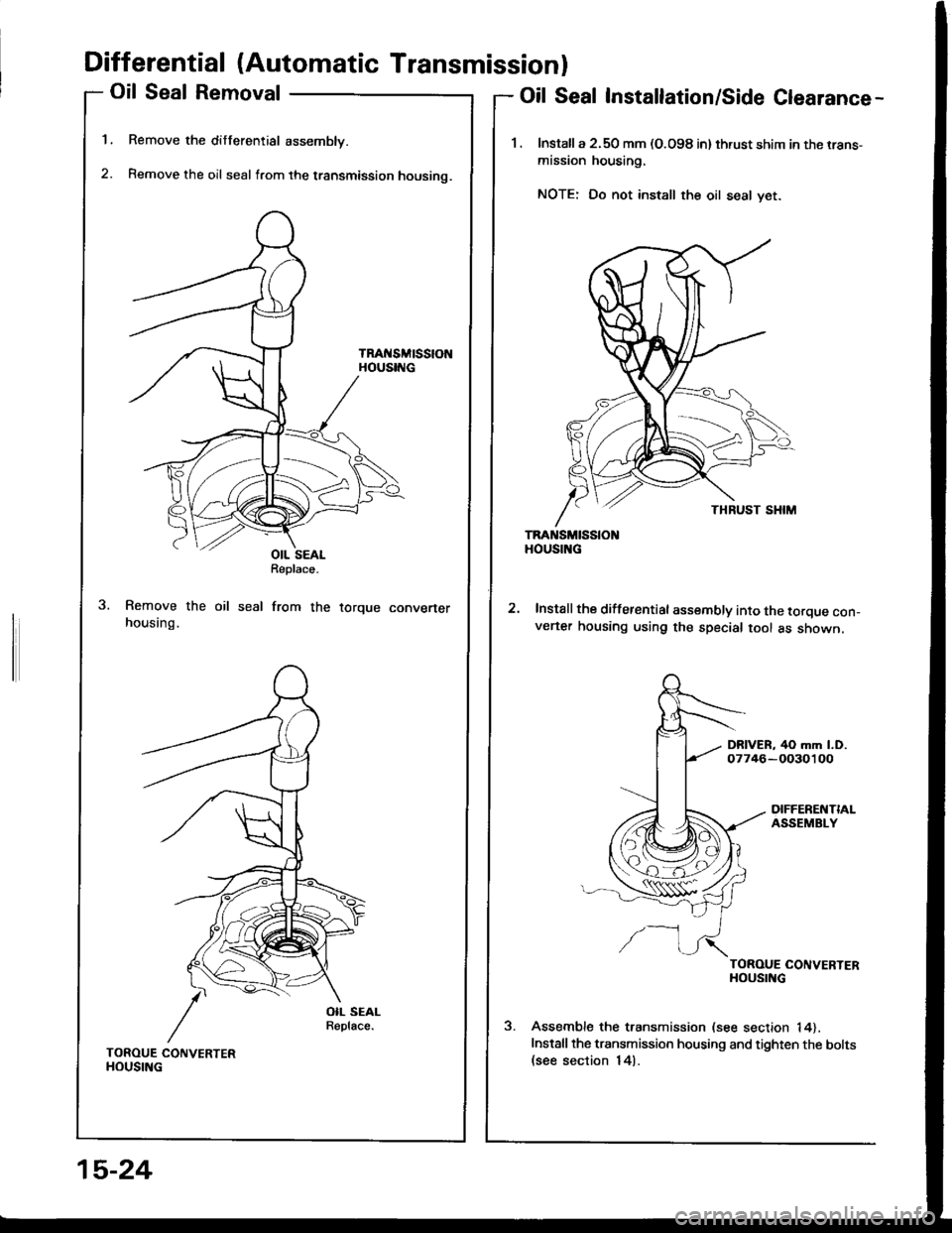
Oil Seal Removal
Remove the differential assembly.
Remove the oil seal from the transmission housino.
TRAt{SMtSStONHOUSING
1.
2.
Oil Seal Installation/Side Clearance-
1. lnstalla 2.50 mm (O.O98 in) thrust shim in the rrans-
mission housing.
NOTE: Do not install the oil seal yet.
TRANSMISSIOHOUSING
Install the differential assembly into the torque con_v€ner housing using the special tool as shown.
DRIVER, 40 mm l.D.07746-OO30100
DIFFERENTIALASSEMBLY
/-l
TOROUE CONVERTERHOUSING
Assemble the transmission (see section 14).
Installthe transmission housing and tighten the bolts(see section 14).
OIL SEALReplace.
seal from therorque convener
TOROUE CONVERTERHOUSING
15-24
Page 591 of 1413
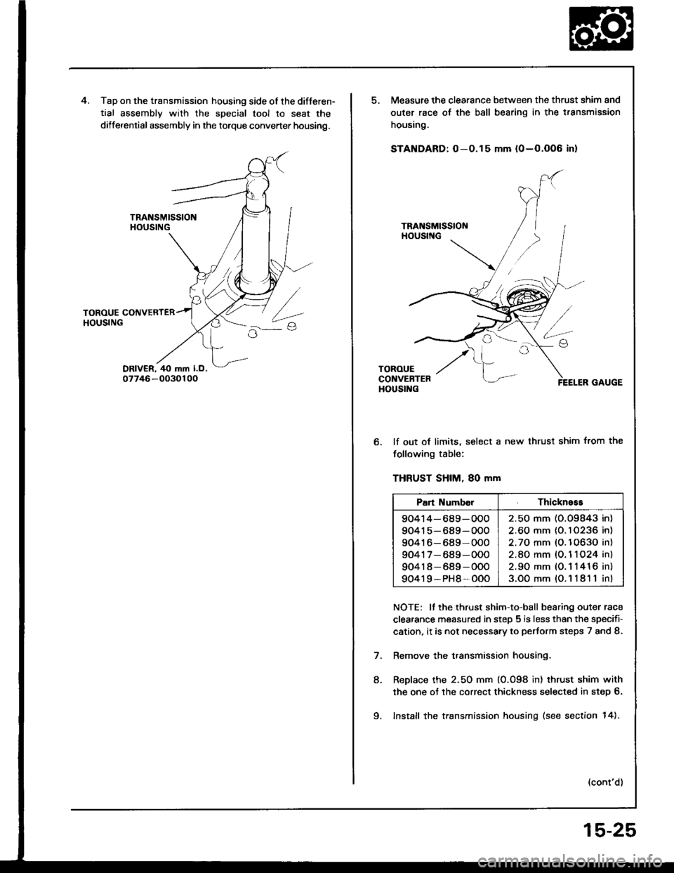
Tap on the transmission housing side of the differen-
tial assembly with the special tool to seat the
dilferential assembly in the torque converter housing.
Measure the clearance between the thrust shim and
outer race of the ball bearing in the t.ansmission
housing.
STANDARD: O-0.15 mm {0-O.OO6 in}
lf out of limits, select a new thrust shim from the
following table:
THFUST SHIM, 80 mm
NOTE: It the thrust shim-to-ball bearing outer race
clearance measured in step 5 is less than the specifi-
cation, it is not necessa.y to pertorm steps 7 and 8.
Remove the transmission housing.
ReDlace the 2.50 mm (0.098 in) thrust shim with
the one oJ the correct thickness selected in step 6.
Install the transmission housing (see section 14).
(cont'd)
8.
Pan Numb€rThickness
90414-689-OOO
90415-689-OOO
90416-689-000
9041 7- 689-000
904r 8-689-OOO
90419-PH8-OOO
2.50 mm (O.O9843 in)
2.60 mm {0. I 0236 in)
2.70 mm (O.10630 in)
2.8O mm (O. 1 1O24 in)
2.90 mm (0.1 1416 in)
3.OOmm{O.11811in)
9.
15-25
Page 595 of 1413
Driveshafts
Inspection
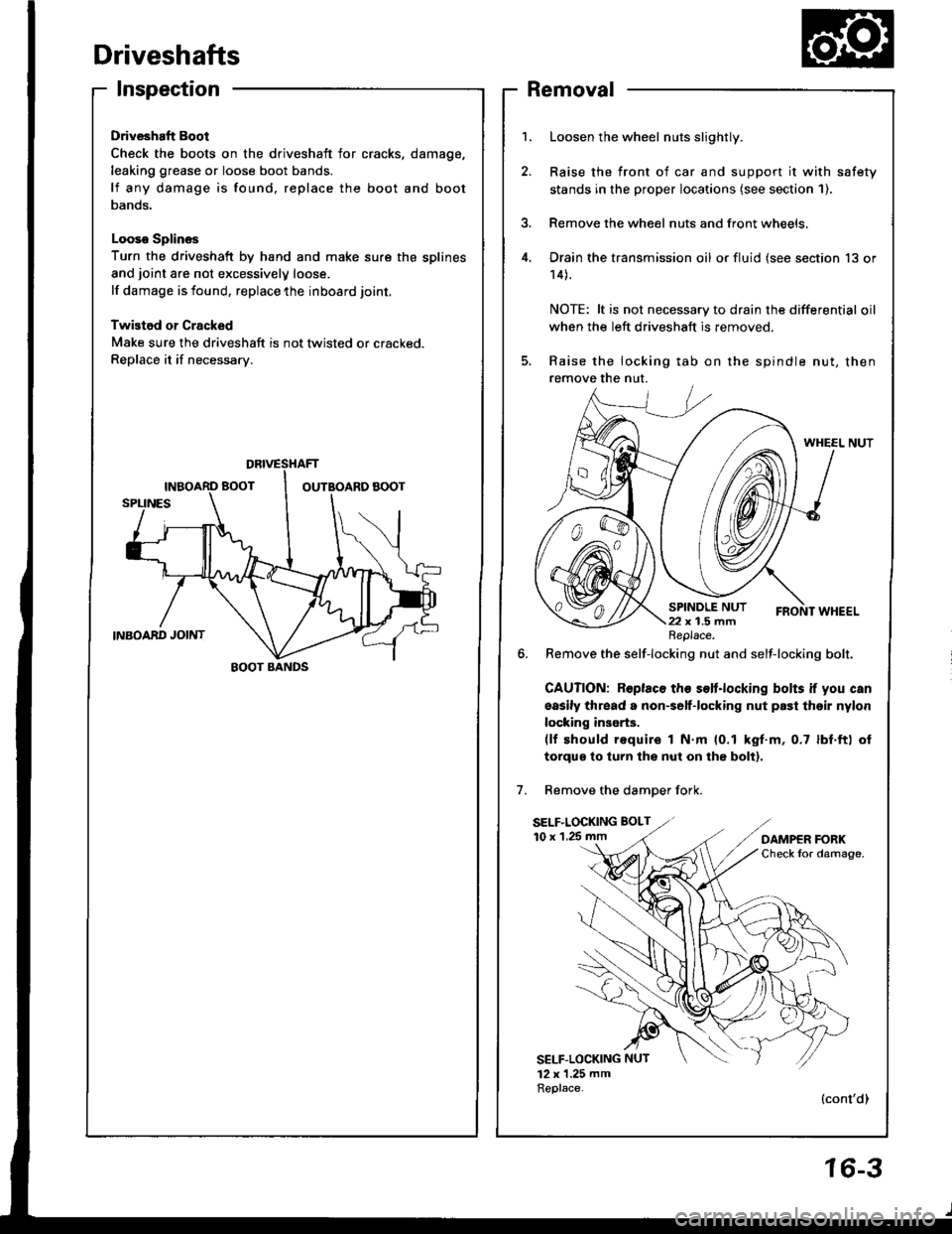
Driveshaft Boot
Check the boots on the driveshaft for cracks,
leaking grease or loose boot bands.
lf any damage is found, replace the boot
Danos.
Looso Splines
Turn the driveshaft by hand and make sure the splines
and joint are not excessivelV loose.
lf damage is found, replace the inboard joint,
Twistod or Cracked
Make sure the driveshaft is not twisted or cracked.
Replace it if necessarv.
damage,
and boot
Removal
Loosen the wheel nuts slightly.
Raise the front of car and support it with safety
stands in the proper locataons (see section 1),
Remove the wheel nuts and front wheels,
Drain the transmission oil or fluid (see section 13 or
14).
NOTE: lt is not necessary to drain the differential oil
when the left driveshaft is removed.
Raise the locking tab on the spindle nut, then
remove the nut.
WHEEL NUT
6. Remove the self-locking nut and self-locking bolt.
GAUTION: Roplaco th€ s€lt.locking bolts if you can
sasily thread a non€elf-locking nut prst thoir nylon
locking inserts.(lf should require I N.m (0.1 kgt.m, 0.7 lbf.ft) ol
torqus to turn lhs nut on the bolt).
Remove the damDer fork.
SELF.LOCKING BOLT
10 x 1.25 mm
SELF-LOCKING NUT
12 x 1.25 mmReplace.(cont'dl
DBIVESTIAFT
EOOT BANDS
Replace.
16-3
Page 596 of 1413
Driveshafts
Removal (cont'dl
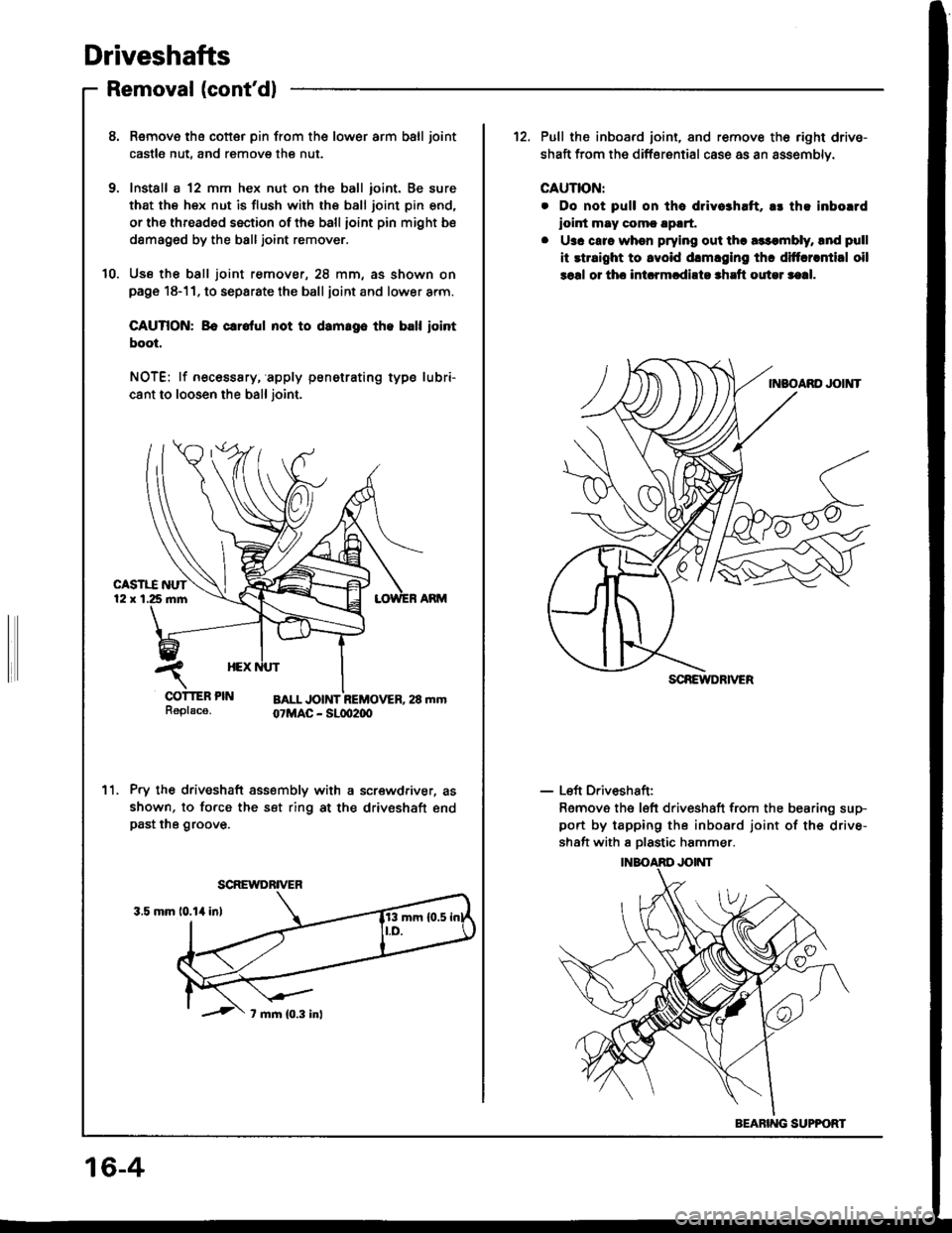
8. Remove tha cotter pin from the lower arm ball joint
castle nut, and remove the nut.
9. Install a 12 mm hex nut on the ball ioint. Be sure
that the hex nut is flush with the ball joint pin end,
or the threaded section of the ball ioint pin might be
damag6d by the balljoint remover.
10. Use th€ ball joint remover, 28 mm, as shown onpage 18-11. to separate the ball joint and lower arm.
CAUTION: Bo crrolul not to damrgo th. ball iointboot.
NOTE: lf necesssry, apply penetrating type lubri-
cant to loosen the ball joint.
Pry the driveshaft assembly with a screwdriver, as
shown, to force the set ring at the driveshaft endpast the groove.
11.
SCREWDRIVER
12. Pull the inboard joint, and remove th6 right drive-
shaft from the differential case as an assemblv.
CAUTION:
. Do not pull on tha dlivo3haft, a! th! inborrd
ioint may comc !p!rt,
. U3c carc when prying out tha a$qnbly, lnd pull
it rtraight to lvoid drmlging thc diftcrrntial oil
soal or thc int.rmcdirto shrft outel saal.
- Left Driveshaft:
Remove the left driveshaft from the bearing sup-
port by tapping the inboard joint of the drive-
shaft with I Dlastic hammer.
SCREIYDRIVER
BEARING SUPPOFT
16-4
Page 603 of 1413
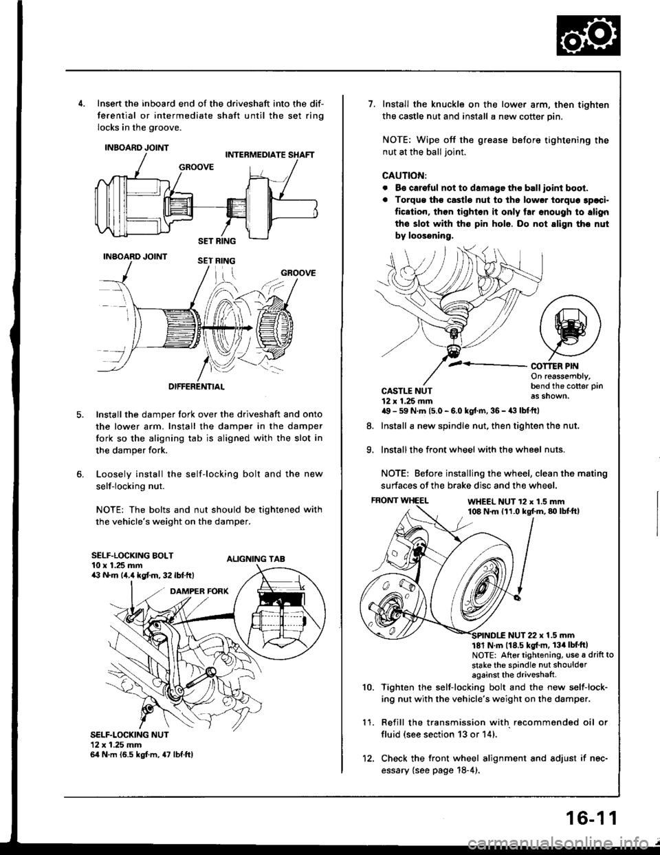
5.
Insert the inboard end of the driveshaft into the dif-
ferential or intermediate shaft until the set ring
locks in the groove.
INBOARD JOINT
INAOARD JOINT
OIFFERENTIAL
Install the damper fork over the driveshaft and onto
the lower arm. Install the damper in the damper
fork so the aligning tab is aligned with the slot in
the damper fork.
Loosely install the self-locking bolt and the new
self-locking nut.
NOTE: The bolts and nut should be tightened with
the vehicle's weight on the damper.
ALIGNING TAB
SELF.LOCKING NUT12x 1.25 mm64 N.m (6.5 kgt m, 47 lbf.ftl
GROOVE
SELF.LOCKING BOLT10 x 1.25 mma:' N.m lir,4 kgt m, 32 lbf.ftt
1.Install the knuckle on the lower arm, then tighten
the castle nut and install a new cotter pin.
NOTE: Wipe off the grease before tightening the
nut at the ball joint.
CAUTION:
. B€ careful not to damago tho ball ioint boot.
. Torqu€ tho castle nut to ths lower torquo 3paci.
fication, then tighlon it only tar snough to slign
the slot with th€ pin hole. Do not align tho nut
by loossning,
COT1ER PIf{On reassembly,bend the cotter pin
as shown.
9.
CASTLE NUT12 x 1.25 rnma9 - 59 N.m 15.0 - 6.0 kgt.m, 36 - a:t lbtftl
Install a new spindle nut, then tighten the nut,
Install the front wheel with the wheel nuts.
NOTE: Before installing the wheel, clean the mating
surfaces of the brake disc and the wheel.
FRONT WHEELWHEEL NUT 12 x 1.5 mm108 N.m (11.0 kgf.m,80lbtft,
8.
1 '�I.
10.
NUT 22 x 1.5 mm181 N m 118.5 kgl'm, 134lbt'ftlNOTE: Altor tightening, use a drift to
stake the sPindle nut shoulderagainst the driveshaft
Tighten rhe self-locking bolt and the new self-lock-
ing nut with the vehicle's weight on the damper.
Refill the transmission with recommended oil or
fluid (see section 13 or 14).
Check the front wheel alignment and adjust if nec-
essary {see page 18-4).
12.
16-1 1
Page 604 of 1413
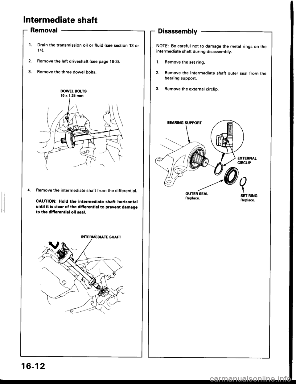
Intermediate shaft
Removal
Drsin the transmission oil or fluid (see section 13 or14).
Remove the left driveshaft (see page 16-3).
Remove the three dow€l bolts.
Remove the intermediate shaft f.om the differential.
CAUTION; Hold the intormediato shaft horizontrl
until it b clear of the dittorential to prevent damago
to thr dittarontial oil so!|.
Disassembly
NOTE: Be careful not to damage the metal rings on theintermediate shaft during disassembly.
1. Remove the set ring,
2. Remove the intermediate shaft outer seal from thebearing support.
3. Remove the eldernalcirclip.
OUTEB SEALReplsce.
2.
t
SET RINGReplace.
16-12
Page 610 of 1413
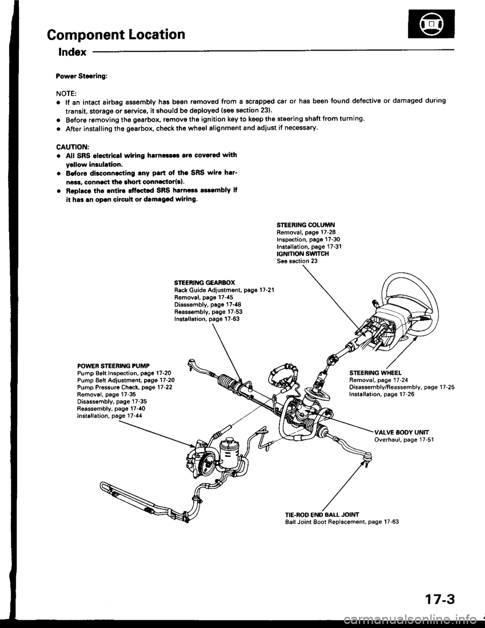
Component Location
lndex
Powar Siooring:
NOTE:
a
a
It an intact airbag ass€mbly has been r€moved from a scrapped car or has been found defective or damaged during
transit. storage or service, it should be doploy€d (see section 23).
Before removing tho gearbox, remove ths ignition key to keep the steering shaft Jrom turning.
After installing the gearbox, check ths whe€l alignment and adiust if necessary.
CAUTION:
. All SRS aloctricll wiring h!m!|$a rrc covcred with
yrllow in3uhtion.
. 8€for€ disconnocling lny ptrt ol thc SRS wiro h!r'
ne*r, connect thc lhort conncctor{3l.
. Rcplsce lhc ontira ttfact d SRS harnccc a$embly il
it hs3 !n oprn circuh 01 dtm!9.d wiring.
SIEERING COLUiINRemoval, page 17-28Inspection, pago 17-30Installation, p6ge 17-31rcNMON SwlTCHSee s6ction 23
STEERII{G GEARBOXRack Guide Adjustment, pag.11-21
Removal, pags 17-45Diossombly, page 17-{8Bea65€mbly, page 17-53Installation, page 17-63
POWEN STEERING PUMPPump Beft Inspoction. page 17-2OPump Eeft Adjustm6nl, pago 17-2OPump Pressurg Ch€ck, page 17-22Removai, p6go 17-35Disassembly, p3gs 17-35Reassombly, psge l7-40lnstallation, page 17-44
STEERING WHEELRemoval. page 17-24Oisassembly/Reassembly, pageInstallation, page 17-2617-25
TIE'ROD END BALL JOINTBall Joint Eoot Replacement, page 17-63
17-3
Page 615 of 1413
System Description
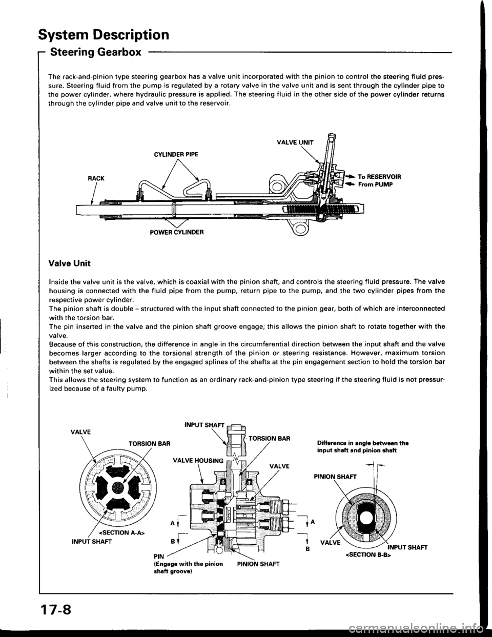
Steering Gearbox
The rack-and-pinion type steering gearbox has a valve unit incorporated with the pinion to control the steering fluid pres-
sure. Steering fluid from the pump is regulated by a rotary valve in the valve unit and is sent through the cylinder pipe to
the power cylinder, where hydraulic pressure is applied. The steering fluid in the other side of the power cylinder returns
through the cylinder pipe and valve unit to the reservoir.
VALVE UNIT
CYLINDER PIPE
POWEB CYLINDER
Valve Unit
Inside the valve unit is the valve, which is coaxial with the pinion shaft, and controls the steering fluid pressure. The valve
housing is connected with the fluid pipe from the pump, return pipe to the pump, and the two cylinder pipes from the
respective power cylinder.
The pinion shaft is double - structured with the input shaft connected to the pinion gear, both of which are interconnected
with the torsion bar.
The pin insened in the valve and the pinion shaft groove engage; this allows the pinion shaft to rotate together with the
Because of this construction, the difference in angle in the circumferential direction between the input shaft and the valve
becomes larger according to the torsional strength of the pinion or steering resistance. However, maximum torsion
between the shafts is regulated by the engaged splines of the shafts at the pin engagement section to hold the torsion bar
within the set value.
This allows the steering system to lunction as an ordinary rack-and-pinion type steering if the steering fluid is not pressur-
ized because of a faulty pump.
VALVE
Difforcnco in .ngl. bo{w€cn thainput shalt rnd pinion !h.tt
ln-1
B
lEngag€ with the pinionshaft groove)
17-8
INPUT SHAFT
Page 616 of 1413
Pressure Control
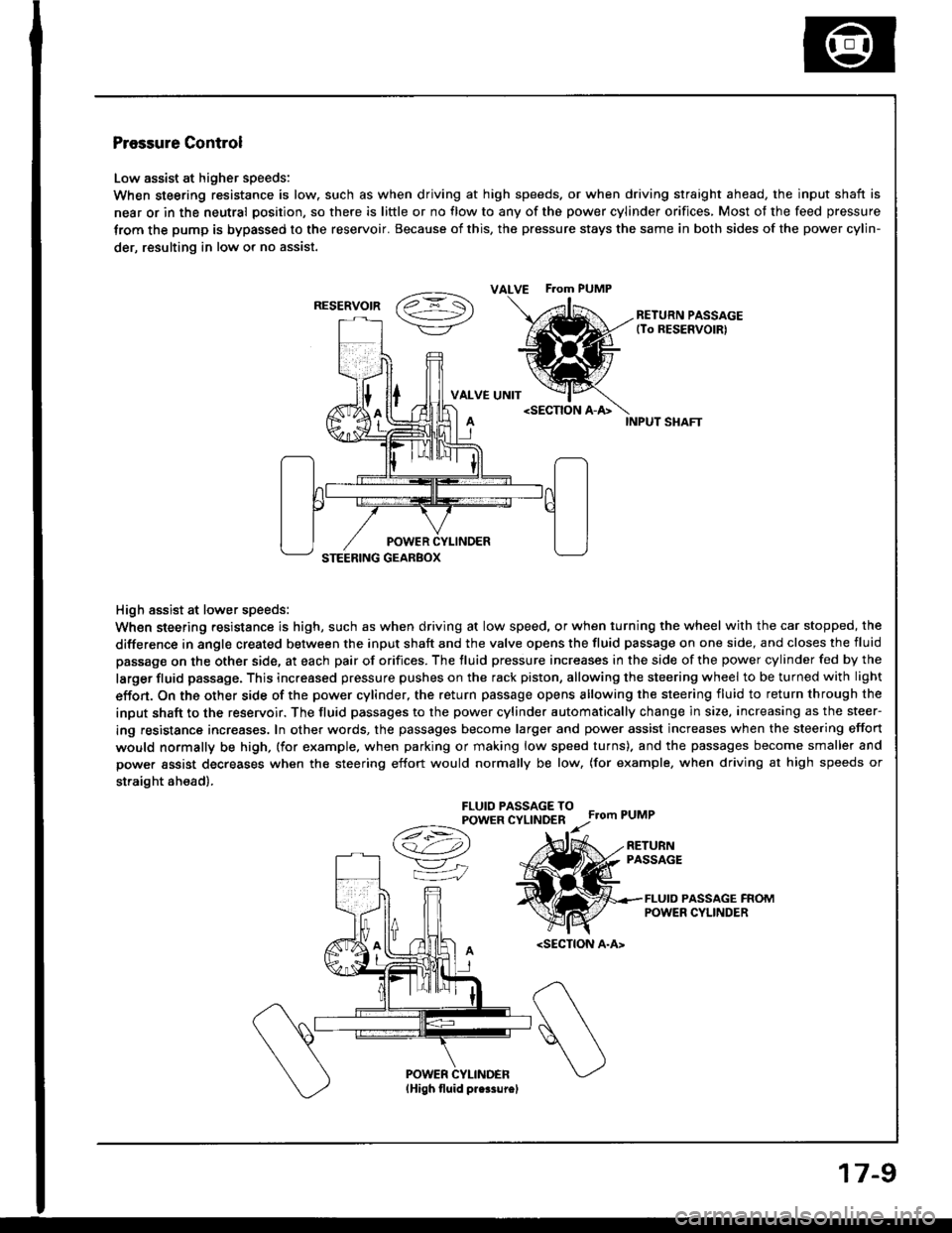
Low assist at higher speeds:
When steering resistance is low. such as when driving at high speeds. or when driving straight ahead, the input shaft is
near or in the neutral position, so there is little or no flow to any of the power cylinder orifices, Most of the feed pressure
trom the pump is bypassed to the reservoir. Because of this, the pressure stays the same in both sides of the power cylin-
der, resulting in low or no assist.
vaz =- S\->/-\7/RETURN PASSAGE(To RESERVOIRI
VALVE UNIT
High assist at lower speeds:
When steering resistance is high, such as when driving at low speed, or when turning the wheel with the car stopped, the
difference in angle created between the input shaft and the valve opens the fluid passage on one side, and closes the fluid
passage on the other side, at each pair of orifices. The fluid pressure increases in the side of the power cylinder fed by the
larger fluid passage. This increased pressure pushes on the rack piston, allowing the steering wheel to be turned with light
effon. On the other side of the power cylinder, the return passage opens allowing the steering fluid to return through the
input shaft to the reservoir. The fluid passages to the power cylinder automatically change in size, increasing as the steer-
ing resistance increases. In other words, the passages become larger and power assist increases when the steering effort
would normally be high, (for example. when parking or making low speed turns). and the passages become smaller and
power assist decreases when the steering effort would normally be low, (for example, when driving at high speeds or
straight ah€ad).
FLUIO PASSAGE TOPOWER CYLINDERFrom PUMP
A
/t-:\
v"
=iJ
RETURNPASSAGE
FLUID PASSAGE FROMPOWER CYLINDER
ALVE F.om PUMP
RESERVOIR
17-9