Engine mount HONDA INTEGRA 1994 4.G Owner's Guide
[x] Cancel search | Manufacturer: HONDA, Model Year: 1994, Model line: INTEGRA, Model: HONDA INTEGRA 1994 4.GPages: 1413, PDF Size: 37.94 MB
Page 554 of 1413
Transmission
Installation
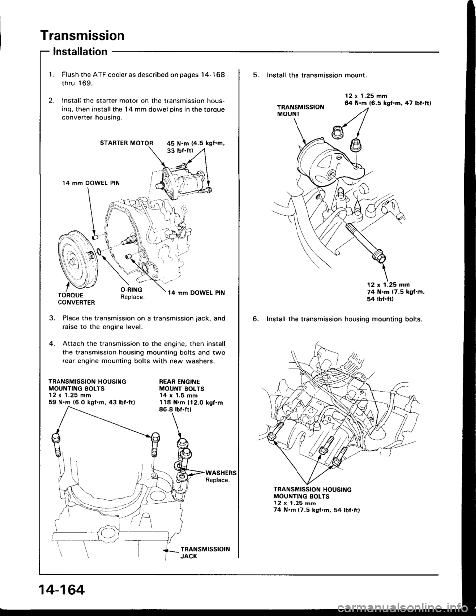
1. Flush the ATF cooler as described on pages I4-168
thru 'l 69.
2. Install the starter motor on the transmission hous-
ing, then installthe l4 mm dowel pins in the torque
converrer nousrng.
STARTER MOTOR
O-RINGReplace.14 mm OOWEL PINTOROUECONVERTER
J.
TRANSMISSION HOUSINGMOUNTING BOLTS
59 N.m 16.0 kgf.m,43 lbl.ftl
Place the transmission on a transmission jack, and
raise to the engine level.
Attach the transmission to the engine, then install
the transmission housing mounting bolts and two
rear engine mounting bolts with new washers.
REAR ENGINEMOUNT BOLTS14 x 1.5 mm
45 N.m 14.5 kgf'm,
'14 mm DOWEL PIN
I
i.'l,i;
14-164
5. Install the transmission mount.
6. Install the transmission
12 x 1.25 mm64 N.m 16.5 kgl.m, 47 lbf.ft)
12 x 1.25 mm74 N.m 17.5 kgf'm,54 rbt'ft)
housing mounting bolts.
MOUNTING BOLTS12 x 1 .25 rnm74 N.m (7.5 kgf'm, 54 lbf.ftl
TRANSMISSION HOUSING
Page 555 of 1413
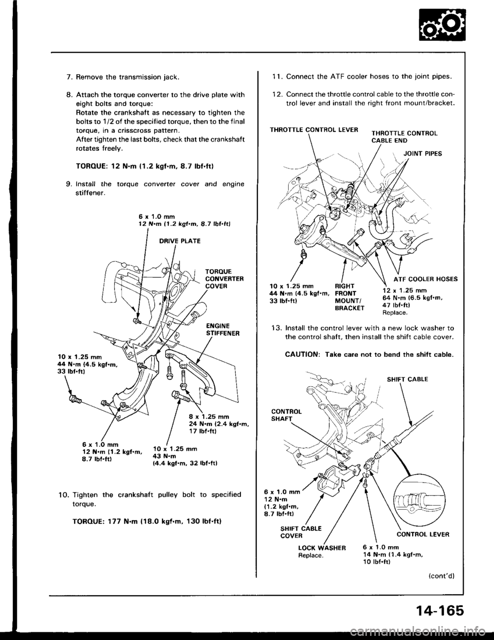
7.Remove the transmission jack.
Attach the torque converter to the drive plate with
eight bolts and torque:
Rotate the crankshatt as necessary to tighten the
bolts to 1/2 of the specilied torque, then to the final
toaque, rn a cnsscross pattern.
After tighten the last bolts, check that the crankshaft
rotates freely.
TOROUE: 12 N.m {1.2 kgl.m.8.7 lbf.ft}
Install the torque converte. cove. and engine
stiffener.
L
9.
6 r 1.O mm12 N.m 11.2 kgt.m, 8.7 lbl.ltl
10.
12 N.m 11.2 kgf.m,8.7 rbt.ft)
Tighten the crankshaft pulley bolt to specified
rorque.
TOROUE: 177 N.m {18.O kgt.m, 130 lbf'ft}
10 x 1.25 mm44 N'm {4.5 kgf.m.33 rbt'frl
8 x '1.25 mm24 N.m (2.4 kgl.m,17 tbf.trl
lO x '1.25 mm43 N.m14.4 kgf.m, 32 lbf.ltl
11. Connect the ATF cooler hoses to the joint pipes.
12. Connect the throttle control cable to the throttle con-
trol lever and install the right front mount/bracket.
THROTTLE CONTROL LEVERTHROTTLE CONTROLCABLE END
JOINT PIPES
12 x 1 .25 mm64 N.m {6.5 kgf.m,47 tbf.ftlReplace.
ATF COOLER HOSES10 x 1.25 mm RIGHT44 N.m (4.5 kgf'm, FRONT33 rbl.ftl MoUNT/BRACK€T
t5.Install the control lever with a new lock washer to
the control shalt. then install the shift cable cover.
CAUTION: Take care not to bend the shift cable.
CONTROLSHAFT
SHIFT CABLE
CONTROL LEVER
6 x 1.0 mm12 N.m{1.2 kgf.m,8.7 lbl.rr)
SHIFT CABLECOVER
LOCK6 x 1.0 mm14 N.m 11.4 kgl.m,10 lbf.fr)
(cont'dl
Replace.ASHER
14-165
Page 611 of 1413
System Description
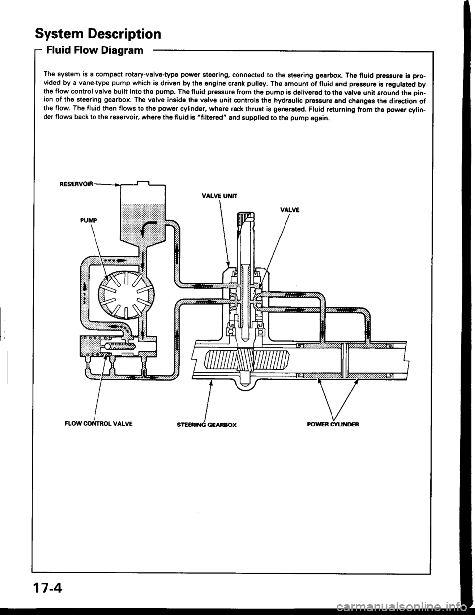
Fluid Flow Diagram
The system is a compact rotary-valvs-type power stssring, connocted to the st€oring gearbox. Th6 fluid pressure is pro-vided by a vane-type pump which is driven by the engine crank pulley. The amount of fluid and pressurs is regulsted bythe flow control valve built into ths pump, The fluid prssaurs from th6 pump is dolivsred to tho valve unit sround the pin-ion of the steering g€arbox. The vslv€ inside the valvs unit controls the hydraulic prossur€ End changos the direction otthe flow. The fluid then flows to the power cylinder, where rack thrust is gen6rat6d. Fluid returning from th6 powsr cylin-der flows back to the .eservoir, where the fluid is 'filtered" and supplied to the pump Egain.
17-4
Page 613 of 1413
System Description
Steering Pump (cont'dl
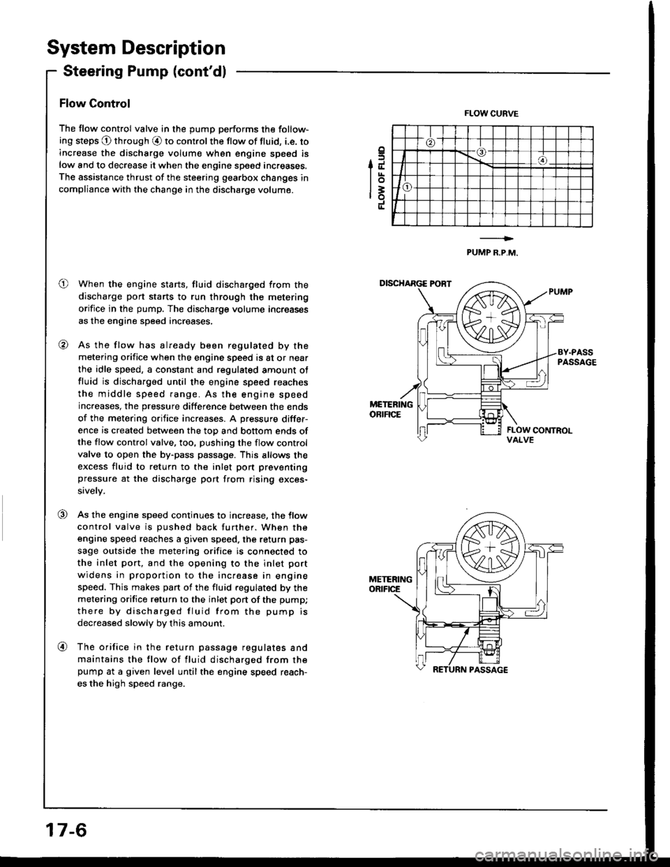
Flow Control
The flow control valve in the pump performs the follow-
ing steps @ through O to control the flow of fluid, i.e. to
increase the discharge volum€ wh6n engine speed is
low and to decrease it when the engine speed increases.
The assistance thrust of the steering gearbox changes in
compliance with the change in the discharge volume.
When the engine starts, fluid discharged from the
discharge port starts to run through the metering
orifice in the pump. The discharge volume increas€s
as the engine speed increases,
As the flow has already been regulated by the
metering orifice when the engine speed is at or near
the idle speed, a constant and regulated amount ot
fluid is discharged until the engine speed reaches
the middle speed range. As the engine speed
increases, the pressure difference between the ends
of the metering orifice increases. A pressure differ-
ence is created between the top and bottom ends ofthe flow control valve, too, pushing the flow control
valve to open the by-pass passage. This allows the
excess fluid to return to the inlet pon preventing
pressure at the discharge port trom rising exces-
sively.
As the engine speed continues to increase, the tlow
control valve is pushed back further. When the
engine speed reaches a given speed. the return pas-
sage outside the metering orifice is connected to
the inlet port, and the opening to the inlet port
widens in proportion to the increase in engine
speed. This makes pan of the fluid regulated by the
metering orifice return to the inlet pon of the pump;
there by discharged fluid from the pump is
decreased slowly by this amount.
The orifice in the return passage regulates and
maintains the flow of fluid discharged from thepump at a given level until the engine speed reach-
es the high speed range.
.5IJ
lot=ro
FLOW CURVE
PUMP R.P,M.
o
@
VALVE
@
@
17-6
Page 651 of 1413
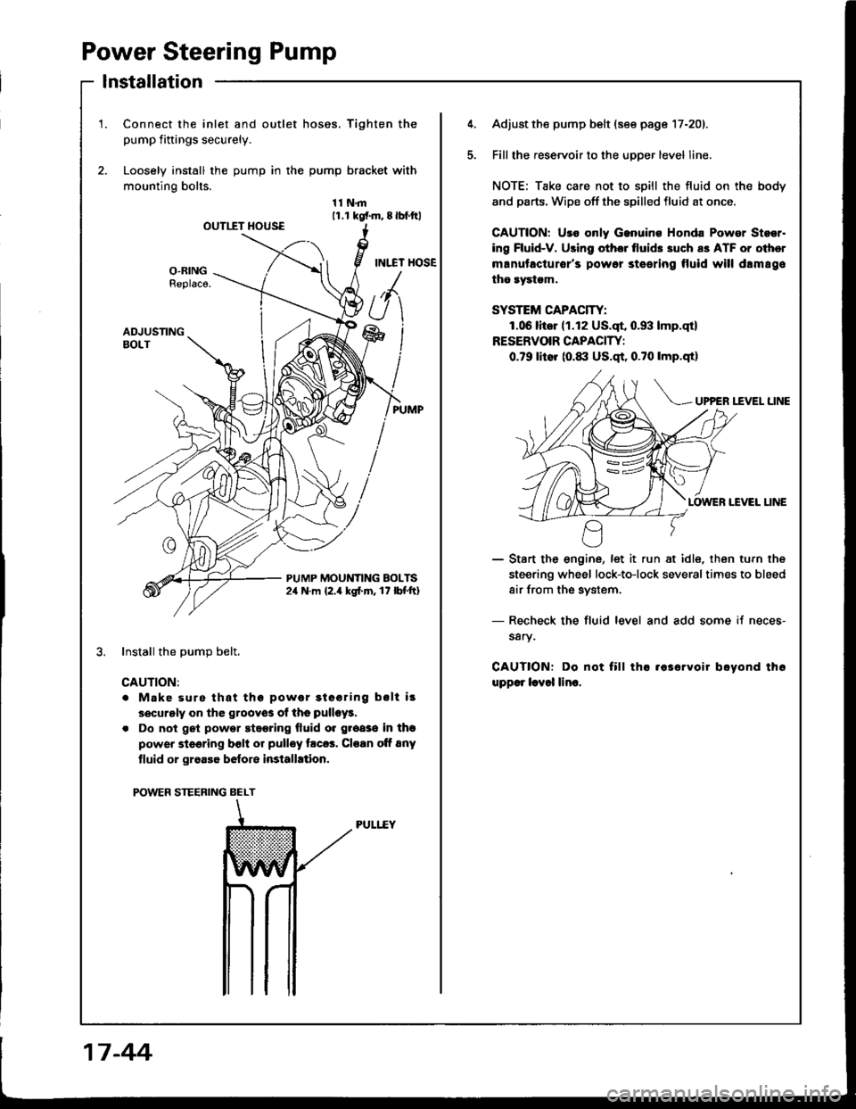
Power Steering Pump
lnstallation
1.Connect the inlet and outlet hoses. Tighten the
pump fiftings securely.
Loosely install the pump in the pump bracket with
mounting bolts.
11N.m11.r kgf.m, 8lbf.ftlOUTIIT HOUSE
INI.TT HOSEO-RINGReplaco.
ADJUSTINGBOLT
PUMP MOUNTING BOLTS2,r N.m {2.4 kgl.m. 17 lbf'ft}
Install the DumD belt.
CAUTION:
. Make surs that thg powor gtooring bslt i!
securgly on the grooyos of ths pulloy!.
. Do not get powor stggring fluid o. groaso in thg
power steering bclt or pulley trc6. Cloan oft 8ny
tluid or groa36 belore installation.
POWER STEERING BELT
PULI..EY
5.
Adjust the pump belt (see page 17-201.
Fill the reservoir to the uoDer level line.
NOTE; Take care not to spill the fluid on the body
and parts. Wipe off the spilled fluid at once.
GAUTION: Uro only Ganuino Honda Powor Stsor.
ing Fluid-V. Using othor tlui& 3uch a3 ATF or oiher
manutacturor's powor steering tluid will drm89e
the rystgm.
SYSTEM CAPACITY:
1.06litor (1.12 US.qt, 0.93 lmp.qt)
RESERVOIR CAPACIW:
0.79 litor (0.1|:| US.qt, 0.?0 lmp.qtl
UP?ER I.fVEL LINE
IEVEI LINE
- Start the engine, let it run at idle, then turn the
steering wheel lock-to-lock severaltimes to bleed
air from the system.
- Recheck the fluid level and add some if neces-
s8ry.
CAUTIONT Do not fill tha .63ervoir boyond th6
upp€r lcvol lino.
17 -44
Page 1059 of 1413
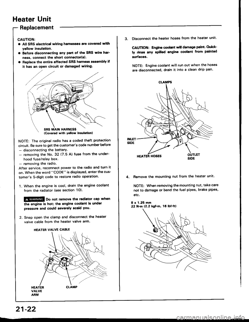
Heater Unit
Replacement
CAUTION:
a All SRS electrical witing hame$os are covoed wlth
yollow insulation.
a Before disconnecting any patt of tho SRS wito har-
neas, connect tha shott connoctol(s|.
a Roplaco th€ enlire sffacted SRS harnosr a$smbly if
it has an opon cilcult or dsmaged wiring.
NOTE: The original radio h8s a coded theft protection
circuit. Be sure to get the customer's code number betors
- disconnecting the bafterY.
- removing the No. 32 (7.5 A) fuse from th€ under-
hood tuse/relav box.- removing the radio
After service. teconnect power to the radio and turn it
on, when the word "CODE" is displayed, enter the cus-
tomer's 5-digit code to restore radio operation.
1. When the engine is cool, dtain the engine coolant
from the radiator (see section 1O).
@@ oo not lomove tho radiator cap whan
the ongine is hol; tha ongino coolant is undot
pressure and could a€voralY tcald you.
2. Snap open the clamp and disconnect the heater
valve cable from the heater valve arm.
HEATER VALVE CABLE
21-22
CLAMFS
3. Disconnect the heater hoses from the heater unit'
CAUTIOII: Engino coobnt will damago paint. orick-
ly dnse any rpilled engine coolant from paintod
surfac63.
NOTE: Engine coolant will tun out when the hoses
are disconnected, drain it into a clean drip pan'
HEATER HOSES
Remove the mounting nut from the heater unit.
NOTE: When removing the mounting nut, take care
not to damage or bend the fuel pipes, brake pipes,
etc.
8 r 1,25 rn|n22 N.m 12.2 kgt.m, tO lbf'ftl
4.
Page 1060 of 1413
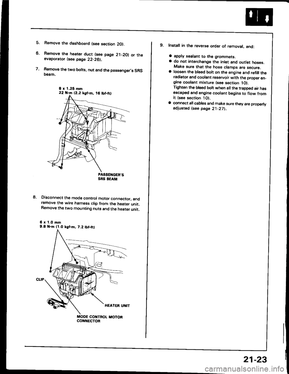
5.
6.
7.
Rsmove the dashboard (see section 2O).
Remove the heater duct (see page 21-20) or theevaporator lse€ page 22-26).
Rsmove the two bolts, nut and the passenger,s SRS(}eam.
PASSEIVGER'SSRS EEAM
Disconnect the mode control motor conngctor, andremove the wire harness clip from the h€8ter unit.Remove the two mounting nuts and the haater unit.
6 r 1.0 mm9.8 .m (l.O kgt.m, 7.2 tbt.frl
MODE COI{TROL I,IOTORcol{t{€cToF
8.
8 x 1,26 mln22 N.m 12.2 kgf.m, 18 tbt.ttl
9. Install in the reverse order of removal, and:
a apply sealant to the grommets.a do not int6rchange the inlet and outl€t hoses.Make sure that the hose clamps are secure.a loosen th€ ble6d bolt on th6 engine and r€fillthetadiator and coolant r€servoir with the propsr en_gine coolant mixture (sse section 1O).Tighten the blsed boh when all the trapped air has6sc8p6d and engine coolant begins to flow fromit (see section 1O).a connect all csbles and make sure they 8re properlyadiusted (see pdge 21-271.
21-23
Page 1101 of 1413
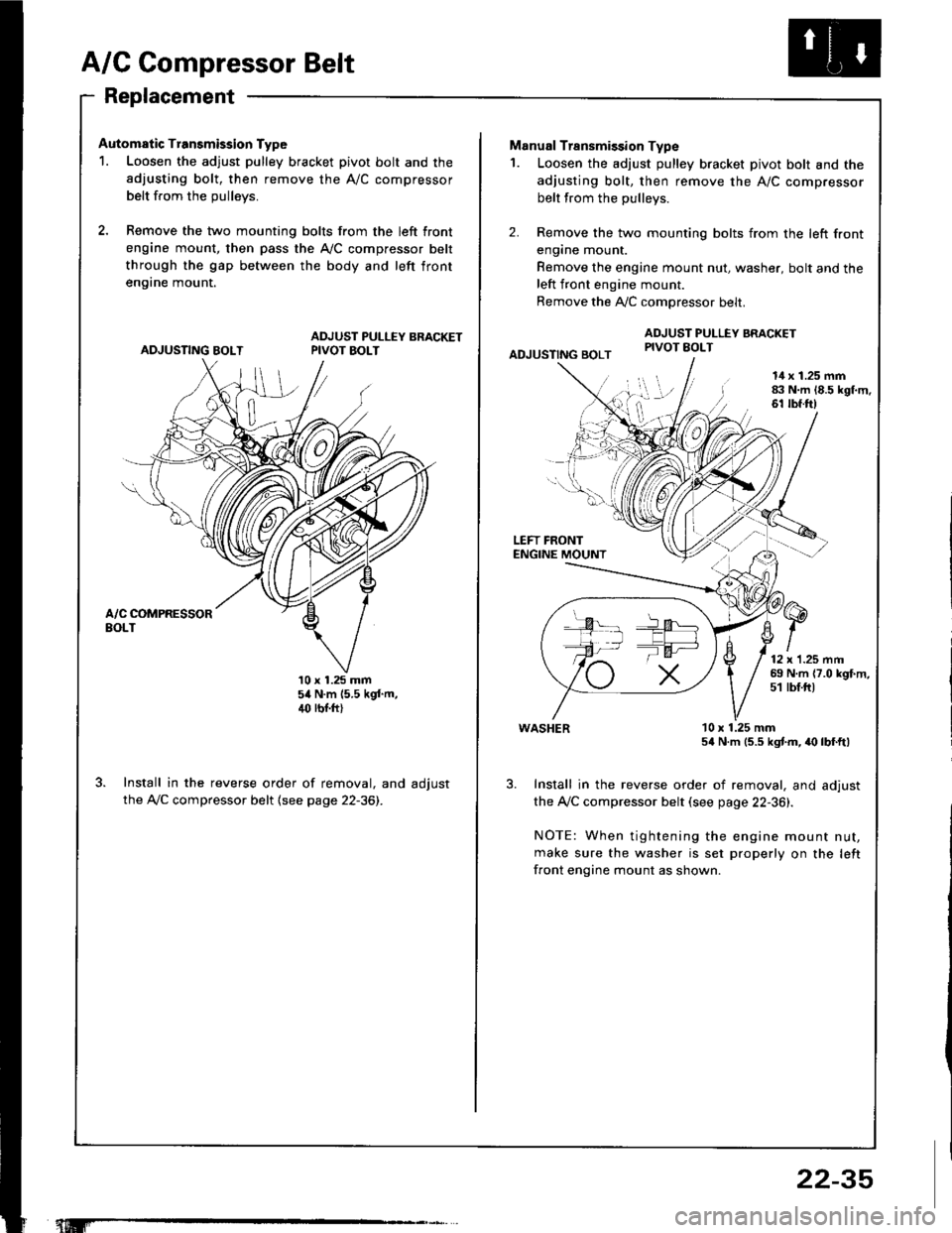
A/C Compressor Belt
Replacement
Automatic Transmission Type
1. Loosen the adjust pulley bracket pivot bolt and the
adjusting bolt, then remove the A/C compressor
belt from the oullevs.
2, Remove the two mounting bolts from the left front
engine mount, then pass the A,/C compressor belt
through the gap between the body and left front
en9rne mount.
ADJUSTING BOLTADJUST PULLEY BRACKETPIVOT BOLT
10 x 1.25 mm54 N.m (5.5 kgf.m,4(' rbr.ft)
Install in the reverse order of removal, and adjust
the A,/C compressor belt (see page 22-36).
"t.M'
22-35
-la ar-
Manual Transmission Type
1. Loosen the adjust pulley bracket pivot bolt and the
adjusting bolt, then remove the A/C compressor
belt from the pullevs.
2. Remove the two mounting bolts from the left front
engane mount.
Remove the engine mount nut, washer, bolt and theleft front engine mount.
Remove the A,./C comoressor belt.
ADJUSTING BOLT
ADJUST PULLEY BRACKETPIVOT EOLT
l!l',
I
14 x 1.25 mm83 N.m 18.5 kgl.m.61 tbf.ft)
LEFT FRONTENGINE MOUNT
12 x'1.25 mm69 N.m {7.0 kgf.m,51 tbf.ftt
WASHER
Install in the reverse order of removal, and adjust
the Ay'C compressor belt (see page 22-36).
NOTE: When tightening the engine mount nut,
make sure the washer is set properly on the left
front engine mount as shown.
10 x 1.25 mm54 N.m (5.5 kgtm, irc lbf.ft)
Page 1109 of 1413
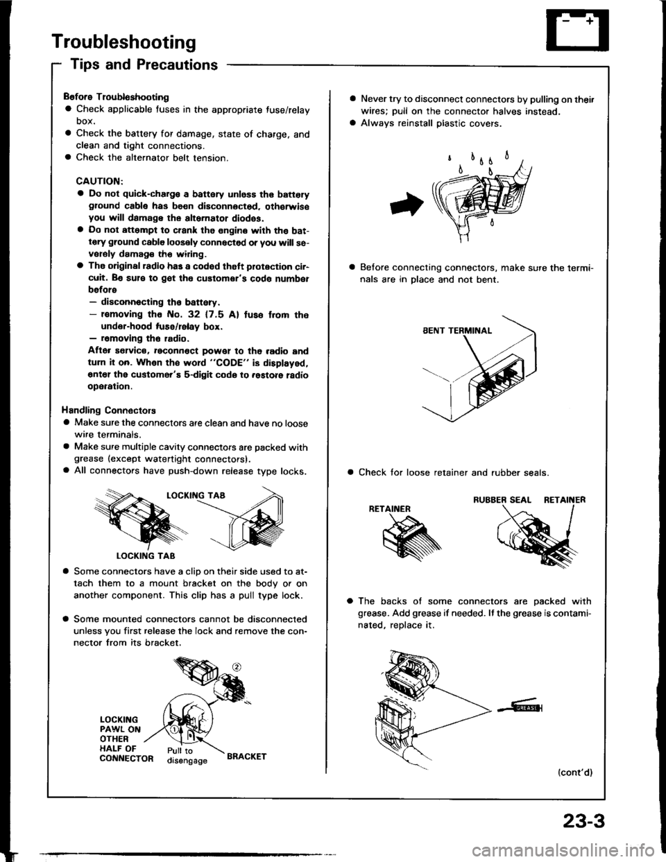
Troubleshooting
Tips and Precautions
Before Troubloshooting
a Check applicable fuses in the appropriate fuse/relay
DOX.
a Check the battery for damage, state of charge, and
clean and tight connections.a Check the alternator belt tension.
CAUTION:
a Do not quick-charg€ a battery unless the batteryground cabla has be€n disconnoctsd. oth€rwisoyou will damage the alternator diodss.a Do not att6mpt to crank the engine with the bat-tery ground cable loosely connectsd or you will se-vorsly damag€ tho widng.
a The original radio has a codod thatt plotection ci.-cuit. Be sul€ to got tho customor's code numbet
before- disconnecting th€ battery.- lomoving tho No. 32 (7.5 Al tuso f.om the
under-hood tuse/lelay box.- removing tho radio.
Aflor s€lvic€. reconn€ct powet to tho radio and
turn it on. Whon the word "CODE" is displayed,
€nt€l the customer'E s-digit codo to .astore ladio
operation.
Handling Connectors
a Make sure the connectors are clean and have no loose
wire terminals.
a Make sure multiple cavity connectots are packed withgrease (except watertight connectors).a All connectors have push-down release type locks.
LOCKII{G TAA
LOCKING TAB
a Some connectors have a clio on their side used to at-
tach them to a mount bracket on the body or on
another component. This clip has a pull type lock.
a Some mounted connectors cannot be disconnected
unless you first release the lock and remove the con-
nector from its bracket.
LOCKINGPAWL ONOTHERHALF OFPull toorsengageCONNECTORBRACKET
23-3
a Never try to disconnect connectors by pulling on thei.
wires; pull on the connector halves instead.
a Always reinstall plastic covers.
Belore connecting connectors, make sure the lermi-
nals are in Dlace and not bent.
a Check tor loose retainer and rubber seals.
RETAINER
a The backs of some connectors are oacked with
grease. Add grease if needed. It the grease is contami-
nated, reDlace it.
(cont'd)
Page 1150 of 1413
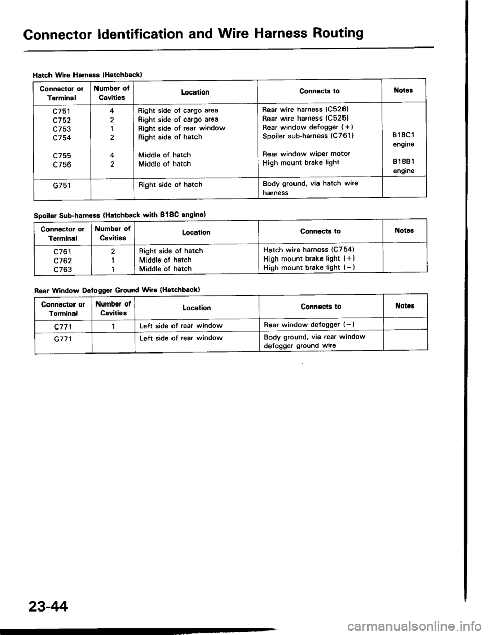
Connector ldentification and Wire Harness Routing
Hatch Wire Harnsss {Hatchbackl
Connector or
Torminal
Numbor ol
CaviliesLocationConnscts tol{otos
c751
c752
L/5J
c754
c755
4
1
4
Right side oJ cargo area
Right side of cargo area
Right side of reat window
Right side of hatch
Middle of hatch
Middle of hatch
Rear wire harness (C526)
Rear wire harness (C5251
Rear window defogger (+ I
Spoiler sub-harness (C761 )
Rear window wiper motot
High mount brake light
818C 1
engine
81 881
engine
G751Right side oJ hstchBody ground, via hatch wire
naaness
Spoilor Sub-harn6ss (Hatchback with B18C snginel
Roar Window Defoggor Ground Wire (Hatchbackl
Connoctor or
Terminal
Number ot
CavitiosLocalionConnocls toNotos
c761
c762
c763
I
1
Right side of hatch
Middle of hatch
Middle of hatch
Hatch wire harness (C754)
High mount btake light ( + )
High mount brake light ( - )
Connoctol or
Tgrminal
Numbor of
Caviti6sLocationConnoctg toNotes
c77'l1Lett side ot rear windowRear window defogger (-)
G771Left side ot rear windowBody ground, via tear window
deJogger ground wi.e
23-4r'i