Engine mount HONDA INTEGRA 1994 4.G User Guide
[x] Cancel search | Manufacturer: HONDA, Model Year: 1994, Model line: INTEGRA, Model: HONDA INTEGRA 1994 4.GPages: 1413, PDF Size: 37.94 MB
Page 110 of 1413
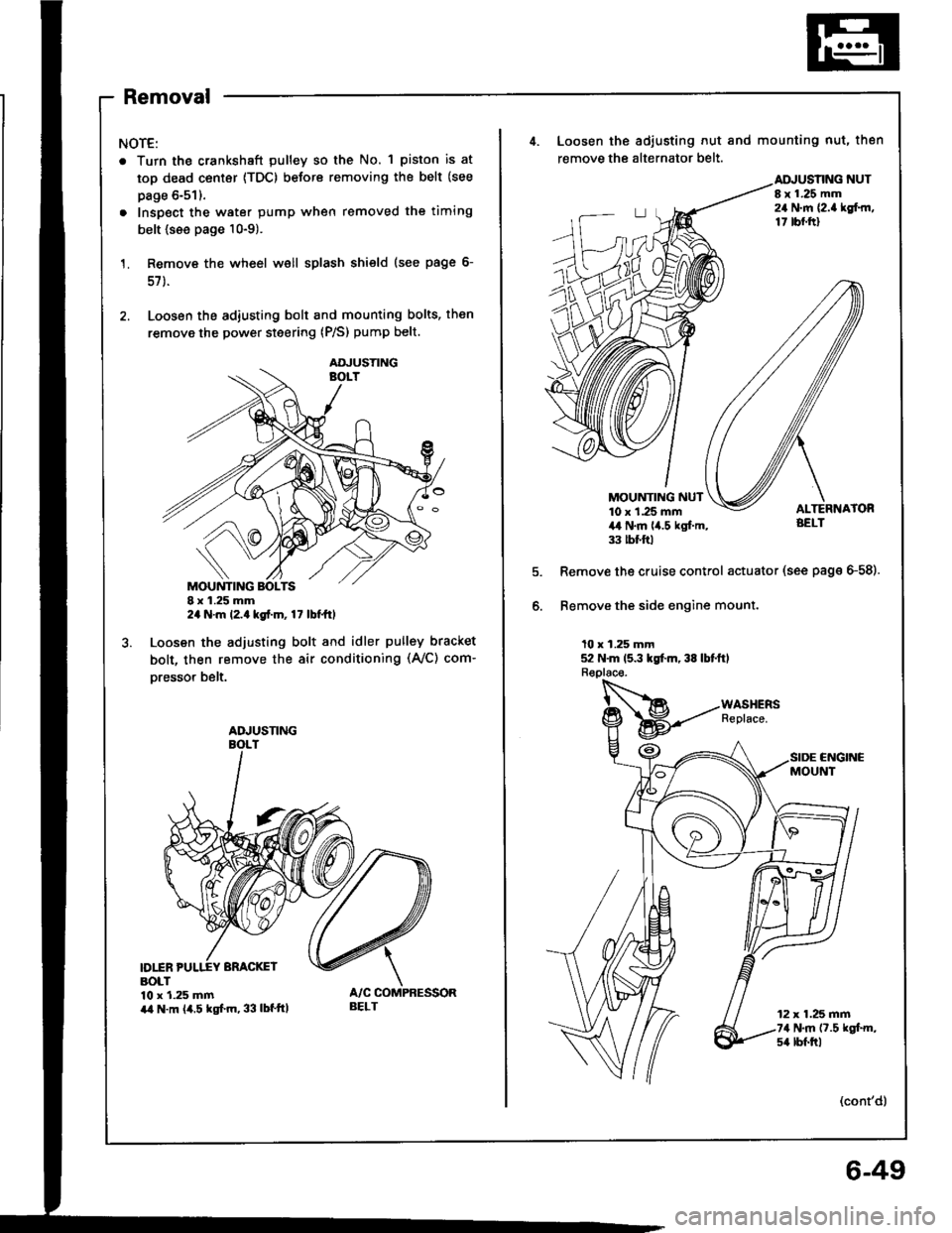
Removal
NOTE:
. Turn the crankshaft pulley so the No. 1 piston is at
top dead center {TDC) before removing the belt (see
page 6-51).
. Inspect the water pump when removed the timing
belt {see page 10-9).
Remove the wheel well splash shield (see page 6-
57 ).
Loosen the adiusting bolt and mounting bolts, then
remove the power steering (P/S) pump belt.
I x 1.25 mm2a N.m l2.a kgt.m, 17 lbt ttl
Loosen the adjusting bolt and idler pulley bracket
bolt, then remove the air conditioning (Ay'C) com-
oresso. belt.
D1INBOLT10 x 1.25 mmira N.m (4.5 kgf.m, 33 lbf'ttl
AOJUSTING
ADJUSNNG
BELT
4. Loosen the adiusting nut and mounting nut, then
remove the alternator belt.
NUTI x 1.25 mm24 N.m {2.a lgf.rn,17 tbf.ftl
MOUNTING NUT10 x 1.25 mm4,t N.m lia.5 kgl.m,33 tbt ftl
Remove the cruise control actuator (see page G58).
Bemove the side engine mount.
10 x 1.25 mm52 N.m 15.3 kgt m, 38 lbtftl
CNGINCMOUNT
12 x 1.25 mm74 N.m (7.5 kgt m,s4 lbf.trl
(cont'd)
6-49
Page 118 of 1413
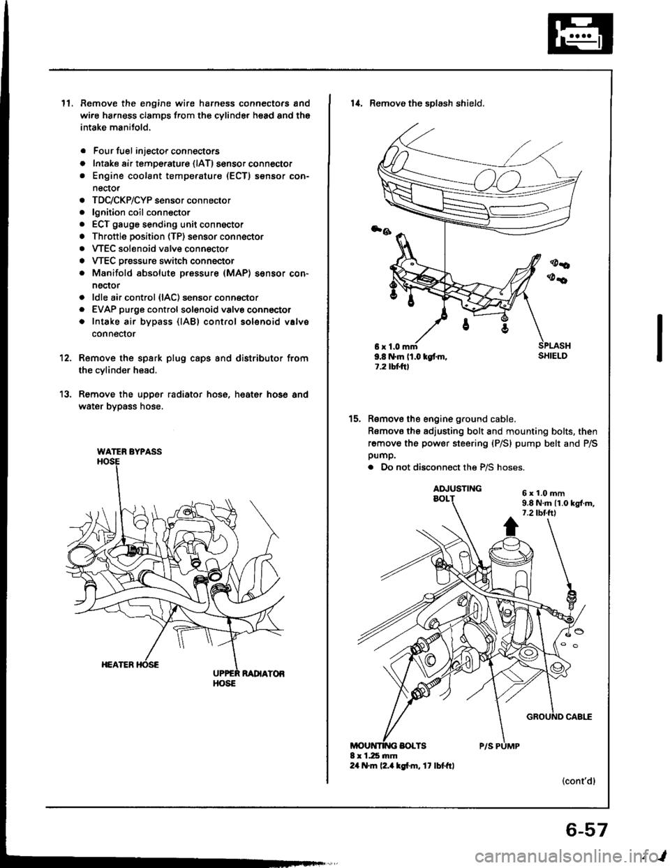
ll.Remove the engine wire harness connectors and
wi.e ha.ness clamps from the cylinder head and the
intake manitold.
Four fuel injector connectors
Intake air tempe.ature {lAT) sensor connector
Engine coolant temperature (ECT) sensor con-
nector
TDC/CKP/CYP sensor connector
lgnition coil conn€ctor
ECT gauge sending unit connector
Throttle position (TP) sensor connector
VTEC solenoid valve connector
VTEC Dressure switch connector
Manifold absolute pressure (MAP) sensor con-
nector
ldle air control {lAC) sensor connector
EVAP purge controlsol€noid valvo connector
Intake air bypass {lABl control solenoid valve
conneclor
a
o
a
o
a
a
a
a
a
a
a
a
a
12.
13.
Remove the spsrk plug caps and distributor from
the cylinder head.
Remove the upper radiator hose, heat€r hose and
water bypass hose.
WATER BYPASS
HOSE
6r1.0mm9.8 N.m (1.0 kgt m,1.2 tbtftl
14. Remove the sDlash shield.
Remove the engine ground cable.
Romovo the adjusting bolt and mounting bolts, then
remove the power steering (P/S) pump belt and P/Spump.
. Do not disconnect the P/S hoses.
(cont'dl
15.
6x1.0mm9.8 N.m 11.0 kgl.m,7.2 tbt.ttl
6-57
,l
Page 119 of 1413
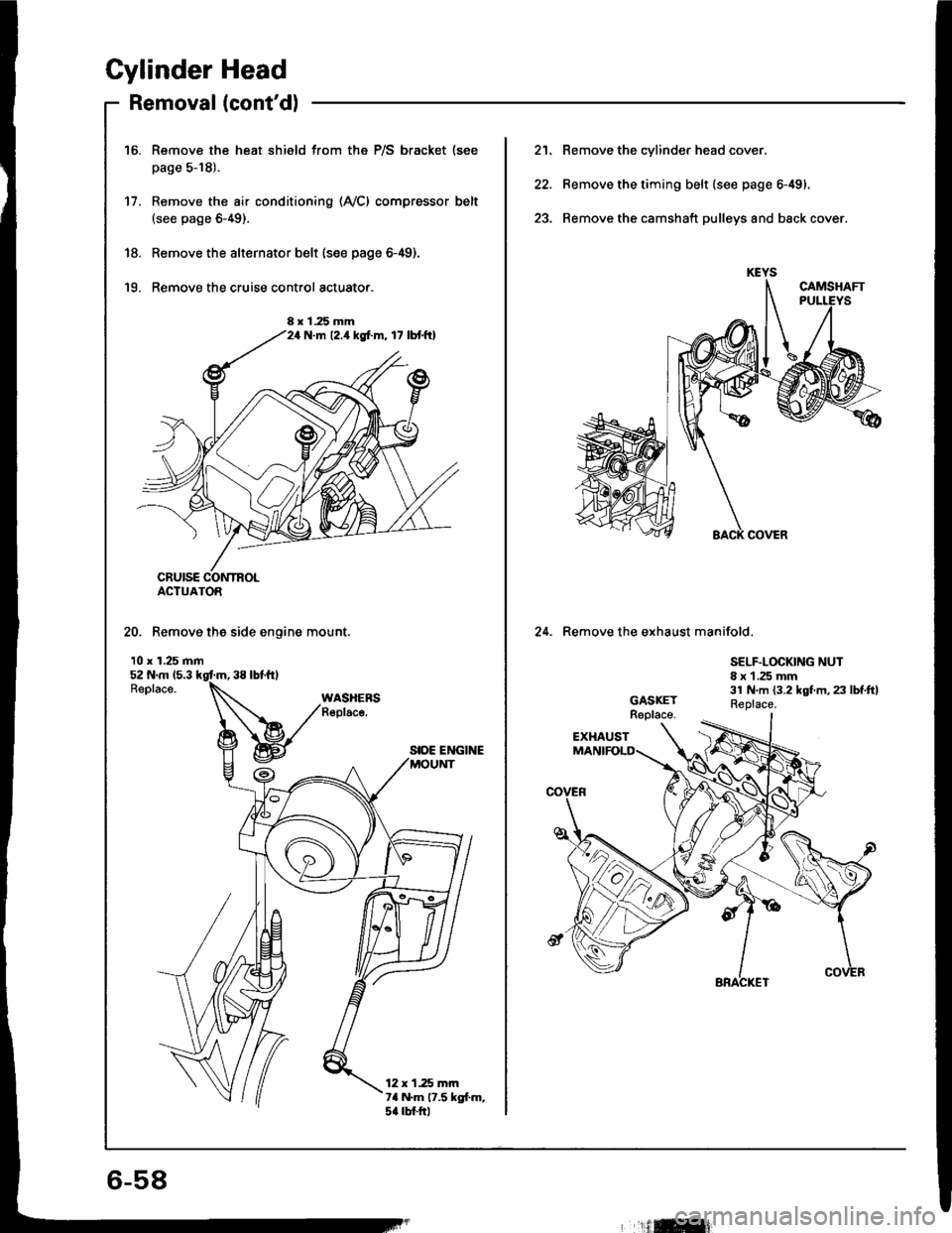
Cylinder Head
Removal (cont'dl
Remove the heat shield from the P/S bracket (see
page 5-18).
Remove the air conditioning (Ay'Cl compressor belt(see page 6-49).
Remove the alternator belt {s€e page 6-49).
Remove the cruise control actuato..
16.
17.
'18.
'19.
ACTUATOR
20. Remove the side engine mount.
10 x 1.25 mm
SIDE ENGINE
12 x 1.25 mrn7a N.m 17.5 kgl.m,5a rbtftl
8 x 1.25 mmN.m 12.4 kgf.m, 17 lbtftl
21. Remove the cylinder head cover.
22. Remove the timing belt (see page 6-49).
23. Remove the camshaft pulleys and back cover.
24. Remove the exhaust manifold.
SELF.LOCKING NUT8 x 1 .25 mm31 N.m {3.2 kgt m, 23 lbf.ftlReplace.
6-58
'ilffi{
Page 174 of 1413
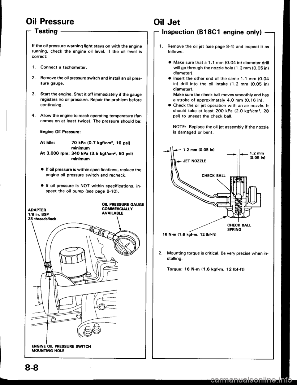
Oil Pressure
Testing
lf the oil pressure warning light stays on with the enginerunning, check the engine oil level. lf the oil level is
correct:
1. Connect a tachometer.
2. Remove the oil pressure switch and install an oil pres-
sure gauge.
3. Stan the engine. Shut it off immediately if the gauge
registers no oil pressure. Repair the problem before
continuing.
4. Allow the engine to reach operating temperatu,e {fancomes on at least twice). The Dressure should be:
Engine Oil Pressure:
At ldle: 70 kPa (0.7 kgf/cmr, 10 psi)
minimum
At 3,OOO lpm: 340 kPa {3.5 kgf/cmz, 50 psi}
minimum
a lJ oil pressure is within speciJications, replace the
engine oil pressure switch and recheck.
a lf oil pressure is NOT within specifications, in-
spect the oil pump (see page 8-1O).
1.2 mm 10.05 in)
'16 N.m (1.6 kgt.m, l2lbt.ftl
Oil Jet
Inspection (B18C1 engine only|
Remove the oil jet (see page 8-4) and inspect it as
follows.
a Make sure that a I .l mm (O.04 in) diameter drill
will go through the nozzle hole {1 .2 mm {O.OS in)
diameterl.
a Insert the other end of the same 1.1 mm (O.O4
in) drill into the oil intake {1.2 rnm {0.05 in}
diameter).
Make sure the check ball moves smoothlv and has
a stroke of approximately 4.0 mm {O. 16 in).a Check the oil jet operation with an air nozzle. lt
should take at least 2OO kPa (2.O kgf/cmr,28
Dsi) 10 unseat the check ball.
NOTE: Replace the oiljet assembly if the nozzle
is damaged or bent.
2. Mounting torque is critical. Be very precise when in-
stalling.
Torque: 16 N.m (1.6 kgt.m, 12lbf.ftl
OIL PRESSURE GAUGECOMMERCIALLYAVAILABI.E
8-8
Page 189 of 1413
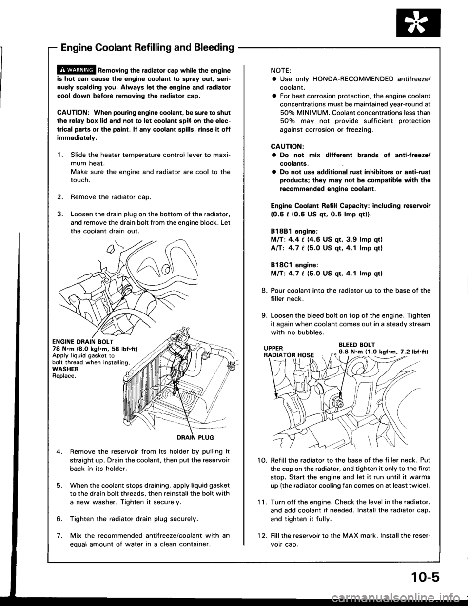
@ ne-oving the radiator cap while the engine
is hot can cause the engine coolant to splay out, seri-
ously scalding you. Always let the engine and radiatol
cool down betore removing the radiator cap.
CAUTION: When poudng engine coolant, be sure to shut
the relay box lid and not to let coolant spill on the elec-
tlical pans or the paint. ll any coolant spills, rinse it otf
immediately.
1. Slide the heater temperature control lever to maxi-
mum heat.
Make sure the engine and radiator are cool to the
touch.
2. Remove the radiator cao.
3. Loosen the drain plug on the bottom of the radiator,
and remove the drain bolt from the enoine block. Let
the coolant drain out.
ENGINE DRAIN BOLT78 N.m {8,O kgt.m, 58 lbt.ftlApply liquid gasker tobolt thread when installing.WASHERReplace.
5.
Remove the reservoir from its holder by pulling it
straight up. Drain the coolant, then put the reservoir
back in its holder.
When the coolant stops draining, apply liquid gasket
to the drain bolt threads, then reinstallthe bolt with
a new washer. Tighten it securely
6. Tighten the radiator drain plug securely.
7. Mix the recommended antifreeze/coolant with an
equal amount of water in a clean container.
NOTE:
. Use only HONDA-RECOMMENOED antifreeze/
coolant.
a For best corrosion protection, the engine coolant
concentrations must be maintained year-round at
50% MINIMUM. Coolant concentrations less than
50% may not provide sufficient protection
against corrosion or freezing.
CAUTION:
a Do not mix ditterent blands ot anti-freeze/
coolants.
a Do not use additional rust inhibitois or anti-rust
products; they may not bs compatibl€ with the
recommgndsd engins coolant.
Engin€ Coolant Retill Capacity: including reservoir
{0.6 t (0.6 US qt, 0.5 lmp qt)).
81881 engine:
MlTt 4.4 | (4.6 US qt, 3.9 lmp qr)
Afft 4.7 [ (5.O US qt,4.1 lmp qt]
Bl8Cl engine:
Mnt 4.7 | (5.0 US qt.4.1 lmp qt)
8. Pour coolant into the radiator up to the base of the
filler neck.
9. Loosen the bleed bolt on top of the engine. Tighten
it again when coolant comes out in a steady stream
with no bubbles.
BLEED BOLT
1O. Refill the radiator to the base of the tiller neck. Put
the cap on the radiator. and tighten it only to the tirst
stop, Stan the engine and let it run until it warms
up (the radiator cooling fan comes on at leasttwice).
11. Turn oft the engine. Check the level in the radiator,
and add coolant it needed. Install the radiator caD,
and tighten it fully.
'1 2. Fill thereservoirto the MAX mark. lnstallthe reser-
voir cap.
9.8 N.m (1.O kgl.m, 7.2 lbf.ftl
Engine Coolant Refilling and Bleeding
10-5
Page 193 of 1413
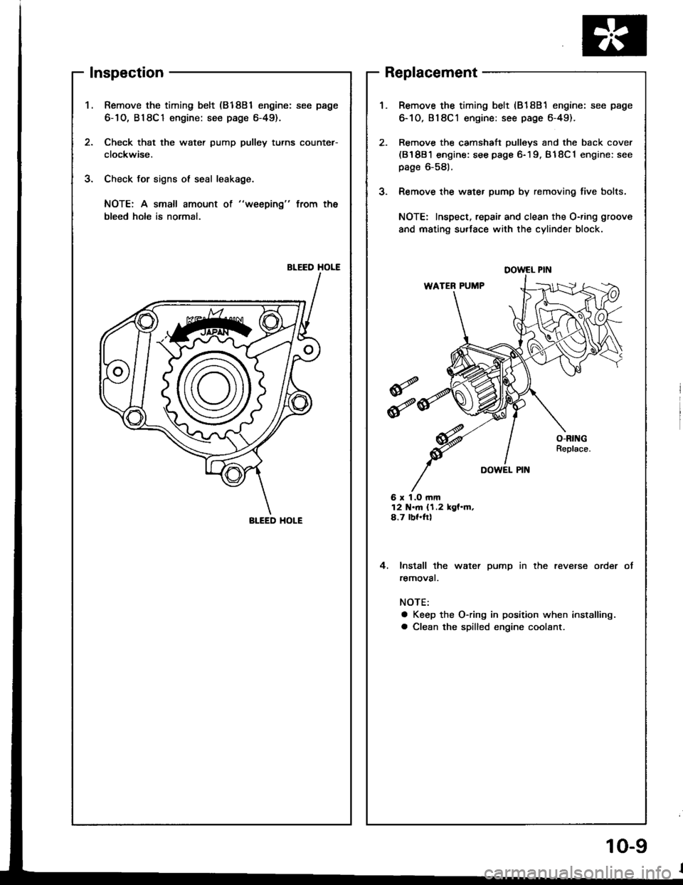
Inspection
Remove the timing belt (81881 engine: see page
6-1O, B18C1 engine: see page 6-49).
Check that the water pump pulley turns counter-
clockwise,
Check for signs ol seal leakage.
NOTE: A small amount ot "weeping" from the
bleed holo is normal,
BLEED HOLE
2.
J.
J.
Replacement
6 r 1.O rnm12 N.m {1.2 kgf.m,4.7 bf.ftl
4. lnstall the water pump in the reverse order
removat.
NOTE:
a Keep the O-ring in position when installing.
a Clean the spilled engine coolant.
Remove the timing belt (818B1 engine: see page
6-10,818C1 engine: see page 6-49).
Remove the camshaft pulleys and the back cover(81881 engine: see page 6-19. B18C1 engine: see
page 6-581.
Remove the water pump by removing five bolts,
NOTE: Inspect, repair and clean the O-ring groove
and mating su.lace with the cylinder block.
DOWEL PIN
BI-EED HOI-E
10-9
Page 268 of 1413
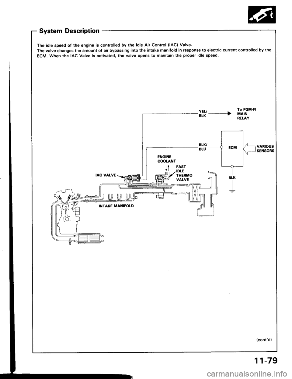
System Description
The idle speed ot lhe engine is controlled by the ldle Air Control {lAC) Valve.
The valve changes the amount ot air bypassing into the intake manifold in response to electric current controlled by the
ECM. When the IAC Valve is activated, the valve opens to maintain the proper idle speed.
#l' ----rTo FGM-FIMAINRELAY
VARIOUSSENSORS
IAC VALVE
FASTIDLETHERMOVALVE
INTAKE MAI{IFOLD
(cont'd)
BLK
r
11-79
Page 269 of 1413
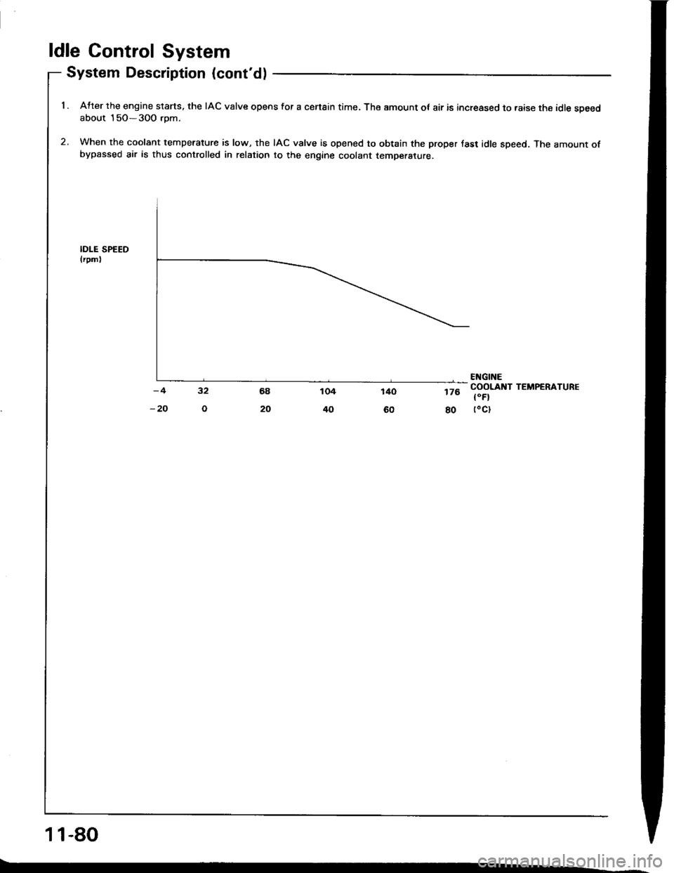
ldle Control System
System Description (cont'd)
1 . Atter the engine slarts. the IAC valve opens for a censin time, The amount ot air is increased to raise the idle soeedabout 15O-3OO rom.
2. When the coolant temperature is low, the IAC valve is opened to obtain the proper fast idle speed. The amount ofbypassed air is thus controlled in relation to the engine coolant temperature.
IDI-E SPEEDlrpm)
176
80
ENGINECOOLANT TEMPERATURE
t"Fl(oct
11-80
Page 271 of 1413
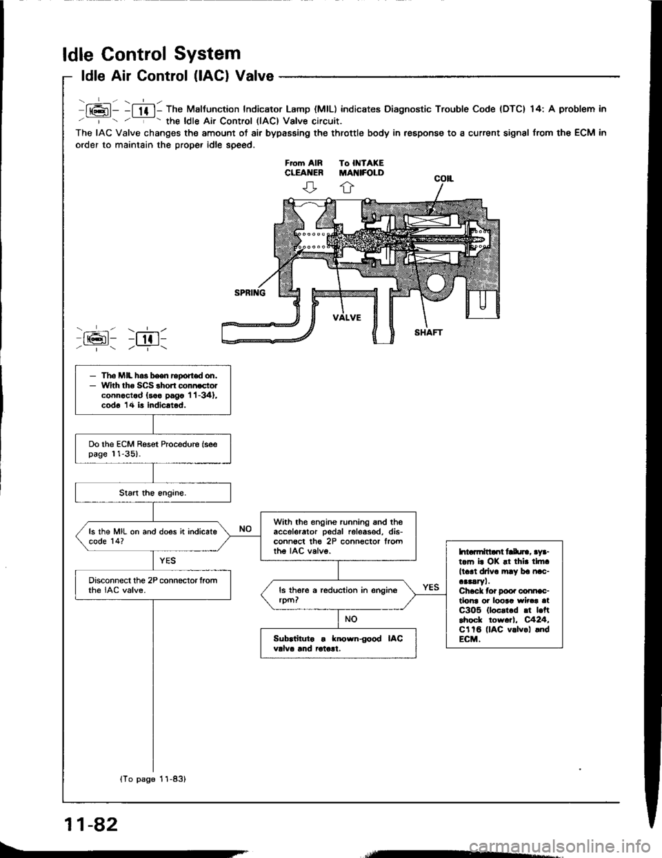
ldle Control System
ldle Air Control (lACl Valve
lt6l- -l lf l- The Maltunction Indicator Lamp (MlL) indicates Diagnostic Trouble Code {DTC} 14: A problem in
' '- the ldle Air Control llAC) Valve circuit.
The IAC Valve changes the amount of air bypasEing the throttle body in respons€ to a current signal from the ECM in
order to maintain the proper idle speed.
ffi: r;611/ | /--T-\
- The MIL h.3 been report don,- With tho SCS shon connoctolconnoctod (soo pago 'l 'l -341,
cod6 14 is indicatod.
Do the ECM Reset Procedure (seepage 11-35).
With the engine running snd theaccelerator pedal releas€d, dis-conn€ct th€ 2P connector frorttho IAC valvo.
ls the MIL on and does it indicatecode 14?
htarmitlaot frlu]., aya-t.m i. OK !t thir tlft.
ll.rl drlv. mly ba nac-aaaaryl.Chack tor Doo. conn€c-tlonr oi loora wirca atC3O5 (loc.t.d .t |.ftlhock tow.tl, C424,Cl tB (lAC v.lvol .ndECM.
Disconnect the 2P connector fromthe IAC valve.
Sub.iituto . known{ood IACvdva lnd iotolt.
{To page 11-83}
11-82
Page 283 of 1413
ldle Control System
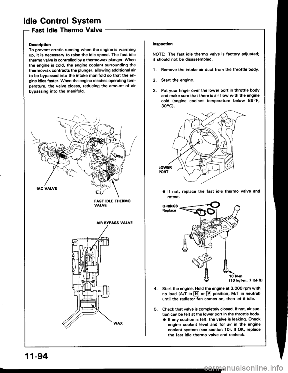
Fast ldle Thermo Valve
DEscliptlon
To prevent erratic running when the engine is warming
up, it is n€cessary to raise the idle speed. The fast idle
thermo valve is controlled by a thermowax plunger, When
the engine is cold. the engine coolant su.rounding the
thermowax contracts the plunger, allowing additional air
to be bypassed into the intake manifold so that the en-
gine idlss taster. When the engine reaches operating tem-
peratur€, the valve closss, reducing the amount of air
bypassing into the manifold.
FAST IDLE THERMOVALVE
AIN EYPASS VALVE
Inspaction
NOTE: The tast idle thermo valve is factory adiustsd;
it should not be disassombl€d.
1. Remove the intake air duct from the throttlg body.
2. Stan the engine.
3. Put your finger over ths lower port in throttle body
and make sure that there is 8ir flow with tho engine
cold (engine coolant temperatute below 86oF,
300c).
a lf not,
retest.
leplace the fast idle thermo valvs and
4.
o-Rr{GsReplace
llo kgf.m, 7 lbt.trl
Start the engine. Hold the sngine at 3.0OO rpm with
no load (A/T in I or @ position, M/T in neutral]
until the radiator fan comes on, then let it idl6.
Check thst valve is completely closed. lt not, air suc-
tion can be telt at the lower Don in the throttle body,
a It any suction is felt, the valve is leaking Check
engine coolant level and for air in tho engine
coolant system (see section 1O). ll OK, rsplace
the fast idle thermo valve and rechock.
11-94