Engine mount HONDA INTEGRA 1994 4.G Owner's Manual
[x] Cancel search | Manufacturer: HONDA, Model Year: 1994, Model line: INTEGRA, Model: HONDA INTEGRA 1994 4.GPages: 1413, PDF Size: 37.94 MB
Page 339 of 1413
InspectionReplacement
Flywheel, Flywheel Bearing
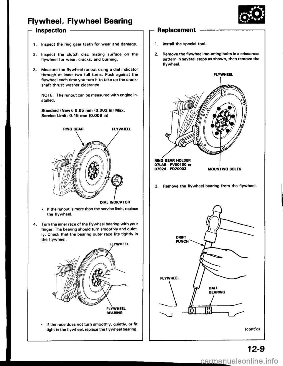
Inspect the ring gear teeth for wear and damage.
Inspect the clutch disc mating surface on the
flywheel fo. wear, cracks, and burning.
Measure the flywheel runout using a dial indicator
through at least two full tu.ns. Push against the
Ilywheel each time you turn it to take up the crank-
shaft thrust washe. clearance.
NOTE; The runout can be measu.ed with engine in-
stalled.
Standard (ttlervl: O.O5 mm (O.002 inl Max.
Service Limit: 0.15 mm 10.006 inl
RING GEABFLYWHEEL
DIAL II{DICATOR
It the runout is more than the service limit, leplace
the flvwheel.
Turn the inner race of the flywheel bearing with your
finger. The bearing should turn smoothly and quiet-
ly, Check that the bearing outer race fits tightly in
the flvwheel.
FLYWHEELBEARING
It the race does not turn smoothly, quietly, or fit
tight in the flywheel, replace the flywheel bearing.
Install the special tool.
Remov€ the flywhe€l mounting bolts in a criascross
pattern in several steps 8s shown, then remove the
tlywheel.
MOUI{TII{G BOLTS
3. Remov€ the flywheel bsaring from th€ tlywheel.
(cont'd)
FLYWHEEL
12-9
Page 347 of 1413
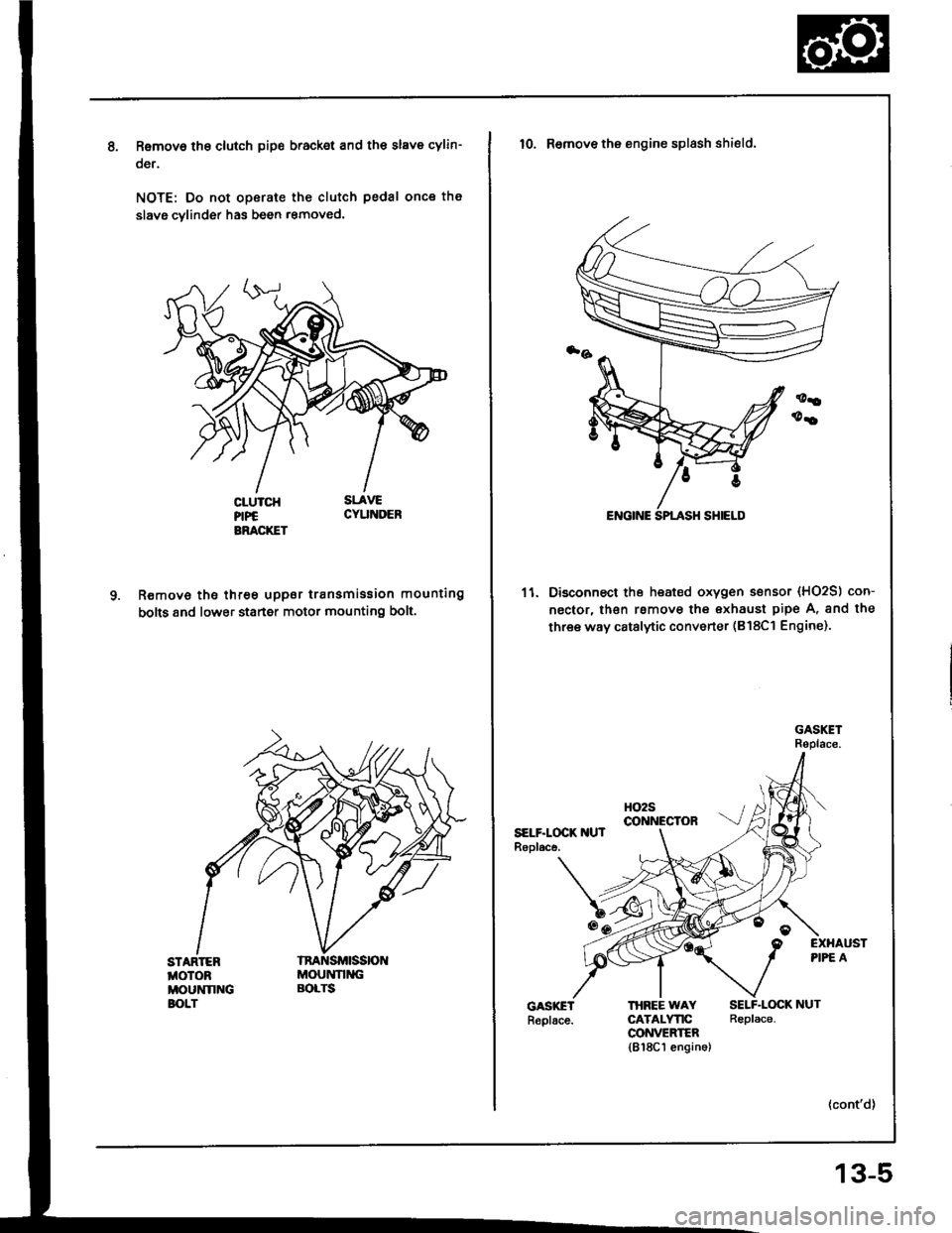
Removo tho clutch pip€ bracket and th€ slave cylin-
oer.
NOTE: Do not operate the clutch pedal once th€
slavg cvlinder has been r€moved.
R€move the three uppor transmission mounting
bolts 8nd lower staner motor mounting bolt.
STARTEBMOTOBMOUNNNGBOLT
MOUNNNGBOLTS
10. Remove the engine splash shield.
11. Disconnect the heated oxygen sensor (HO2S) con-
nector, lhsn rsmove the exhaust pipe A, and the
three way catalytic converter (B18Cl Engine).
HO2Sco NEctoRSELF.LOCK IIUTRopl.ce.
EXHAUSTPIPE A
THBEE WAYCATALYTICCONVEEIER1818C1 engin6)
SELF.LOCK NUTReplace.
13-5
Page 349 of 1413
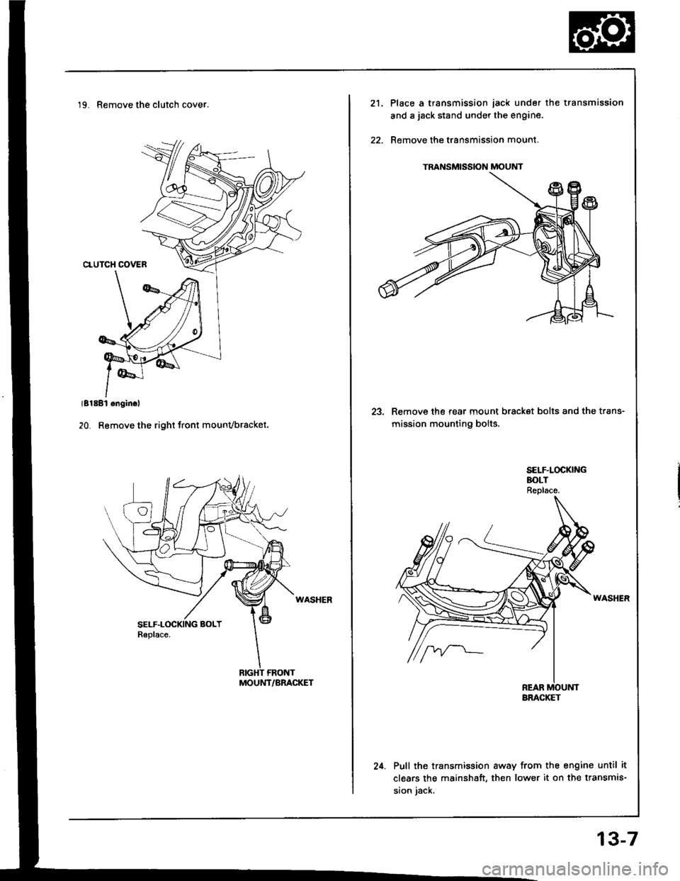
19. Remove the clutch cover.
MOUNT/BRACKET
TRANSMISSION MOUNT
21.Place a transmission iack under the transmission
and a jack stand under the engine.
Remove the transmission mount.
23. Remove the rear mount bracket bolts and the trans-
mission mounting bolts.
24. Pull the transmission away from the engine until it
clears the mainshaft, then lower it on the transmis-
sion iack.
BRACKET
13-7
Page 384 of 1413
Transmission
Reassembly (cont'd)
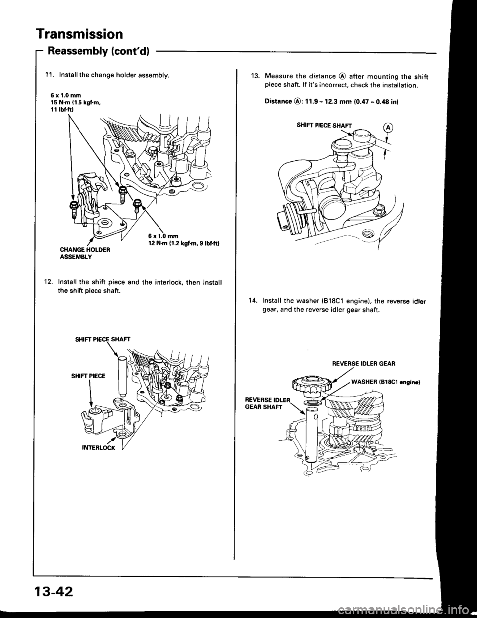
11. Install the change holder assembly.
6x1.0mm15 N.m (1.5 kgf.m,11 tbf.ftl
CHANGE HOLDERASSEMBLY
Install the shift piece
the shift piece shaft.
and the interlock, then install12.
13-42
13. Measure the distance @ after mounting the shiftpiece shaft. lf it's incorrect, check the installation.
Distance O: 11.9 - 12.3 mm 10.47 - 0.48 in)
14.lnstall the washer (B18C1 engine), the reversegear. and the reverse idler gear shaft.
idlo.
REVERSE IDLER GEAR
Page 388 of 1413
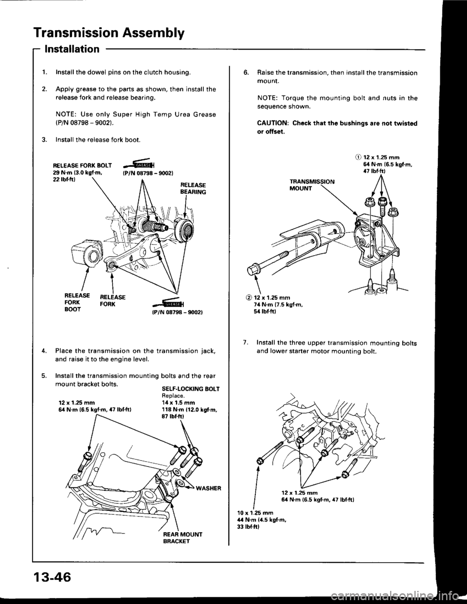
Transmission Assembly
1. Inst€llthe dowel pins on the clutch housing.
2. Apply grease to the parts as shown, then install the
release fork and release beaaing.
NOTE: Use only Super High Temp Urea Grease(P/N 08798 - 9002).
3. Install the release fork boot.
lnstallation
22 tbt-ttl
BELEASE FORK BOLT29 N.m (3.0 kgl.m,tPlN 08798 - 90021
RELEASEBEARING
@
I
{P/N 08798 - 90021
Place the transmission on the transmission iack,
and raise it to the engine level.
Install the transmission mounting bolts and the rear
mount bracket bolts sELF-LocKrNG BoLT
RELEASE REEASEFORK FORKBOOT
12 x 1.25 mm6it N.m 16.5 kgl.m, 47 lbf.ftl
Replace.14 x 1.5 mm
13-46
6, Raise the transmission, then install the transmission
mounI.
NOTE: Torque the mounting bolt and nuts in the
sequence shown.
CAUTION: Check that the bushings are not twistod
or offset,
O 12 x 1.25 mm54 N.m {6.5 kgt m,47 tbtfrl
7. Install the three upper transmission mounting
and lower starter motor mounting bolt.
bolts
10 x 1.25 mm44 N.m lil,s kgt m,33 tbf.ftl
@ 12 x 1.25 mm7,1 N.m 17.5 kg{.m,5/r lbtftl
12 x 1.25 mm64 N.m 16.5 kgf.m, 47 lbf.ftl
Page 395 of 1413
The Automatic Transmission is a combination of a 3-e,ement torque convefter and triple-shaft electfonically controlled
automatic transmission which provides 4 speeds forward and 1 speed reverse. The entire unit is positioned in line with
the engine.
Torque Converter, Gears and Clutches
The torque converter consists of a pump, turbine and stator assembly in a single unit, The torque converter is connected
to the engine crankshaft so they turn together as a unit as the engine turns. Around the outside of the torque converter
is a ring gear which meshes with the starter pinion when the engine is being staned. The entire torque converter assem-
bly serves as a flywheel while transmitting power to the transmission mainshaft.
The transmission has three parallel shafts, the mainshaft. countershaft and sub-shaft. The mainshatt is in line with the
engine crankshaft.
The mainshaft includes the clutches for 1 st, and 2ndl4th, and gears for 3rd. 2nd, 4th, reverse and l st (3rd gear is in-
tegral with the mainshaft, while reverse gear is integral with the 4th gear).
The countershaft includes the 3rd clutch and gears Ior 3rd, 2nd,4th, reverse, lst and parking. Reverse and 4th gears
can be locked to the countershaft at its center, providing 4th gear or reverse, depending on which way the selector is moved.
The sub-shaft includes the lst-hold clutch and gears for 1st and 4th
The gears on the mainshait are in constant mesh with those on the countershaft and sub-shaft. When certain combina-
tions of gears in the transmission are engaged by the clutches, power is transmitted from the mainshaft to the counter-
shaft via the sub-shatt to provide @, E, tr. tr and @ position.
Electronic Control
The electronic control system consists of the Transmission Control Module {TCM), sensors, and 4 solenoid valves. Shift-
ing and lock-up are electronically controlled for comfortable driving under all conditions.
The TCM is located below the dashboard, behind the left side kick panel on the driver's side.
Hydraulic Control
The valve bodies include the main valve body, secondary valve body, regulator valve body. servo body, and lock-up valve
body throuqh the respective separator plates.
They are bolted on the torque converter housing.
The main valve body contains the manual valve, 1-2 shift valve, 2-3 shift valve, Clutch Pressure Cont.ol (CPC) valve,
4th exhaust valve, relief valve, and oil pump gears.
The secondary valve body contains the 4-3 kick-down valve,3-2 kick-down valve,2-3 orifice cont.ol valve, 3-4 shitt
valve, orifice control valve. modulator valve, and servo control valve
The regulator valve body contains the pressure regulator valve. lock-up control valve, torque converter check valve, and
cooler check valve.
The servo bodv contains the servo valve which is integrated with the reverse shift fork, throttle valve B, and accumulators.
The lock-ug valve bodv contains the lock-up shift valve and lock-up timing B valve. and is bolted on the secondary valve
body.
Fluid from the regulator passes through the manual valve to the various control valves.
Shitt Control Mochanism
Input to the TCM i.om various sensors located throughout the car determines which shift control solenoid valve should
be activated.
Activating a shift control solenoid valve changes modulator pressure, causing a shift valve to move. This pressurizes
a line to one of the clutches. engaging that clutch and its corresponding gear.
Lock-up Mechanism
In @ position. in 2nd, 3rd and 4th, and E position in 3rd, pressurized tluid can be drained from the back of the tor-
que converter through an oil passage, causing the lock-up piston to be held against the torque converter cover. As this
takes Dlace, the mainshaft rotates at the same speed as the engine crankshatt. Together with hydraulic control, the TCM
optimizes the timing ol the lock-up mechanism.
The lock-up valves control the range of lock-up according to lock-up control solenoid valves A and B, and throttle valve B
When lock-up control solenoid valves A and B activate, modulator pressure changes. Lock-up control solenoid valves
A and B are mounted on the torque converter housing, and are controlled by the TCM.
(cont'd)
14-3
Page 417 of 1413
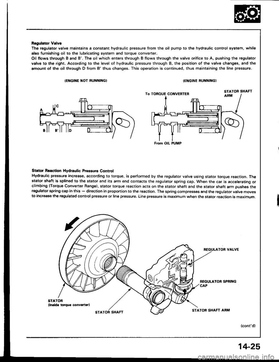
Rcgulator Valve
The r€gulator valve maintains a constant hydraulic pressure from the oil pump to the hydraulic control system, whil€
alEo furnishing oil to the lubricating system and torque convener.
Oil flows through B and B'. The oil which enters through B flows thfough the valve orifice to A, pushing the regulator
valve to the right. Acco.ding to the level of hydraulic pressure through B, the position of the valve changes, and the
amount of the oil thlough D from B'thus changes. This operation is continued. thus maintaining the line pressure.
IEI{GINE ]IIOT RUNNINGI{ENGINE RUNNING)
Siator Reaction Hydtaulic Pressure Control
Hydraulic pressure increase, according to torque, is performed by the regulator vslve using stator torque reaction. Thestator shaft is splined to the stator and its a.m end contacts the fegulator spring cap. When the car is accelerating orclimbing (Torque Convener Range). stator torque reaction acts on the stator shalt and the stator shaft arm pushes thersgulator spring cap in this - direction in proportion to the reaction. The spring compresses and the regulator valve movesto increase the regulated control pressure or line pressure. Line pressure is maximum when the stator reaction is maximum.
TOR VALVE
(cont'd)
From OIL PUMP
STATOR SHAFTSTATOR SHAFT ARM
14-25
Page 431 of 1413
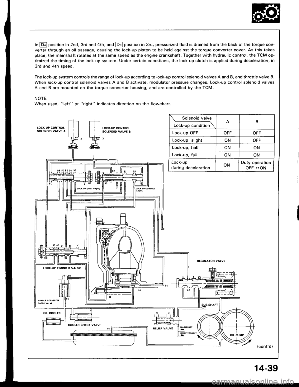
In E position in 2nd, 3rd and 4th, and @ position in 3rd, pressurized fluid is drained from the back of the torque con-
verter through an oil passage, causing the lock-up piston to be held against the torque converter cover. As this takes
place, the mainshaft rotates at the same speed as the engine crankshaft. Together with hydraulic control, the TCM op-
timized the timing ot the lock-up system. Under certain conditions, the lock-up clutch is applied during deceleration, in
3rd and 4th sDeed.
The lock-up system controls the range of lock-up according to lock-up control solenoid valves A and B, and throttle valve B.
When lock-up control solenoid valves A and B activate. modulator pressure changes. Lock-up control solenoid valves
A and B are mounted on the torque converter housing, and are controlled by the TCM.
NOTE:
When used, "left" or " tight" indicates direction on the tlowchart.
LOCK IJP COIITBOL
Solenoid valve
L""f."p "."aiti""\B
Lock-up OFFOFFOFF
Lock-up, slightONOFF
Lock-up, halfONON
Lock-up. fullONON
Lock-up
during decelerationONDuty operation
OFF -ON
LOCI( UP TIMII{G B VAIVE
{cont'd)
ott coot€R
14-39
Page 481 of 1413
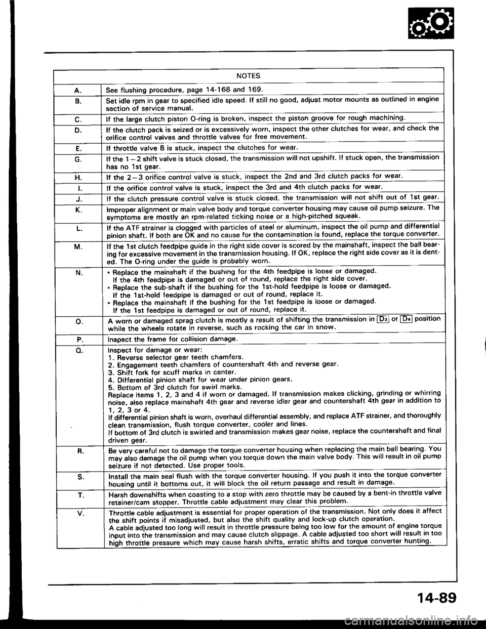
NOTES
A.See flushing procedure, page l4-168 and 169.
B.Set idle rpm in gear to specitied idle speed. lf still no good, adiust motor mounts as outlined in engine
section of service manual.
lf the large clutch piston O-ring is broken, inspect the piston groove for rough machining.
lf the clutch pack is seized or is excessively worn, inspect the other clutches Jor wear, and check the
orifice control valves and throttle valves for free movement.
E.It throttle valve B is stuck, inspect the clutches for wear.
lf the 1-2 shift valve is stuck closed, the transmission will not upshift. lI stuck open, the transmission
has no lst gear.
H.lf the 2-3 orifice control valve is stuck, inspect the 2nd and 3rd clutch packs for wear.
ll the orifice cont.ol valve is stuck, inspect the 3rd and 4th clutch packs for wear.
lf the clutch Dressure control valve is stuck closed, the transmission will not shilt out of 1st gear.
K.improper alignment or main valve body and torque converter housing may cause oil pump seizure. The
symptoms ale mostly an rpm-related ticking noise or a high-pitched squeak.
L.ll the ATF strainer is ctogged with panicles of steel or aluminum, inspect the oil pump and ditferential
pinion shaft. lt both are OK and no cause lor the contamination is found, replace the torque converter.
M.lf the 1st clutch feedpipe guide in the right side cover is scored by the mainshaft, inspect the ball bear-
ing for excessive movement in the transmission housing. lf OK. replace the right side cover as it is dent-
ed. The O-ring under the guide is probably worn.
N.ReDlace the mainshstt if the bushing for the 4th feedpipe is loose or damaged.
It the 4th feedpipe is damaged or out ot tound, replace the right side cover'
Replace the subjshaft it thtbushing for the 1st-hold Jeedpipe is loose or damaged.
lf the 1st-hold feedpipe is damaged or out of round, replace it.
Replace the mainshaft if the bushing lor the 1st feedpipe is loose or damaged.
lf the lst feedpipe is damaged or out ot round, replace it.
o.A *o- r, da."s"d "p-g clutch is mostly a result of shifting the transmission in El or Lq! position
while the wheels rotate in reverse, such as rocking the car in snow.
P.InsDect the frame for collision damage.
o.Inspect for damage or wear:
1. Reverse selector gear teeth chamfers.
2. Engagement teeth chamters of countershaft 4th and reverse gear.
3. Shift fork for scutt marks in center.
4. Differential Dinion shaJt for wear under pinion gears.
5. Bottom of 3rd clutch for switl marks.
Replace items 1 , 2, 3 and 4 it worn or damaged. lf transmission makes clicking, grinding or.whirring
noise, atso replace mainshaft 4th gear and reverse idler gear and countershaft 4th gear in addition to
1,2,3ot4.lf ditiersntial Dinion shaft is worn, overhaul differential assembly, and replace ATF strainel, and thoroughly
clean transmission, tlush torque convertet, cooler and lines.
lf bottom of 3rd clutch is swirled and transmission makes gear noise, replace the countershaft and tinal
driven gear.
R.Be wry careful not to dsmage the torque converter housing when replacing the main ballbearing. You
may al;o damage the oil pump when you torque down the main valve body. This will result in oil pump
seizure it not detected. Use proper tools.
qInstall the main seal tlush with the torque converter housing, lf you push it into the torque converter
housing until it bottoms out. it will block the oil return passage and result in damage.
T,Harsh do\/vnshiJt"\./l,'hen coasting to a stop with zero th.ottle may be caused by a bent-in throttle valve
retainer/cam stopper. Throttle cable adjustment may clear this problem.
ifuitle cable adjustment is essential for proper operation of the transmission. Not only does it affect
the shift points if misad,usted, but also the shift quality and lock-up clutch operation'
A cable adjusted too long will result in throttle pressure being too low for the amount of engine torque
input into ihe trsnsmission and may cause clutch slippage. A cable adjusted too short will result in too
hi;h throttle pressure which may cause harsh shitts, erratic shrfts and torque con
14-89
Page 494 of 1413
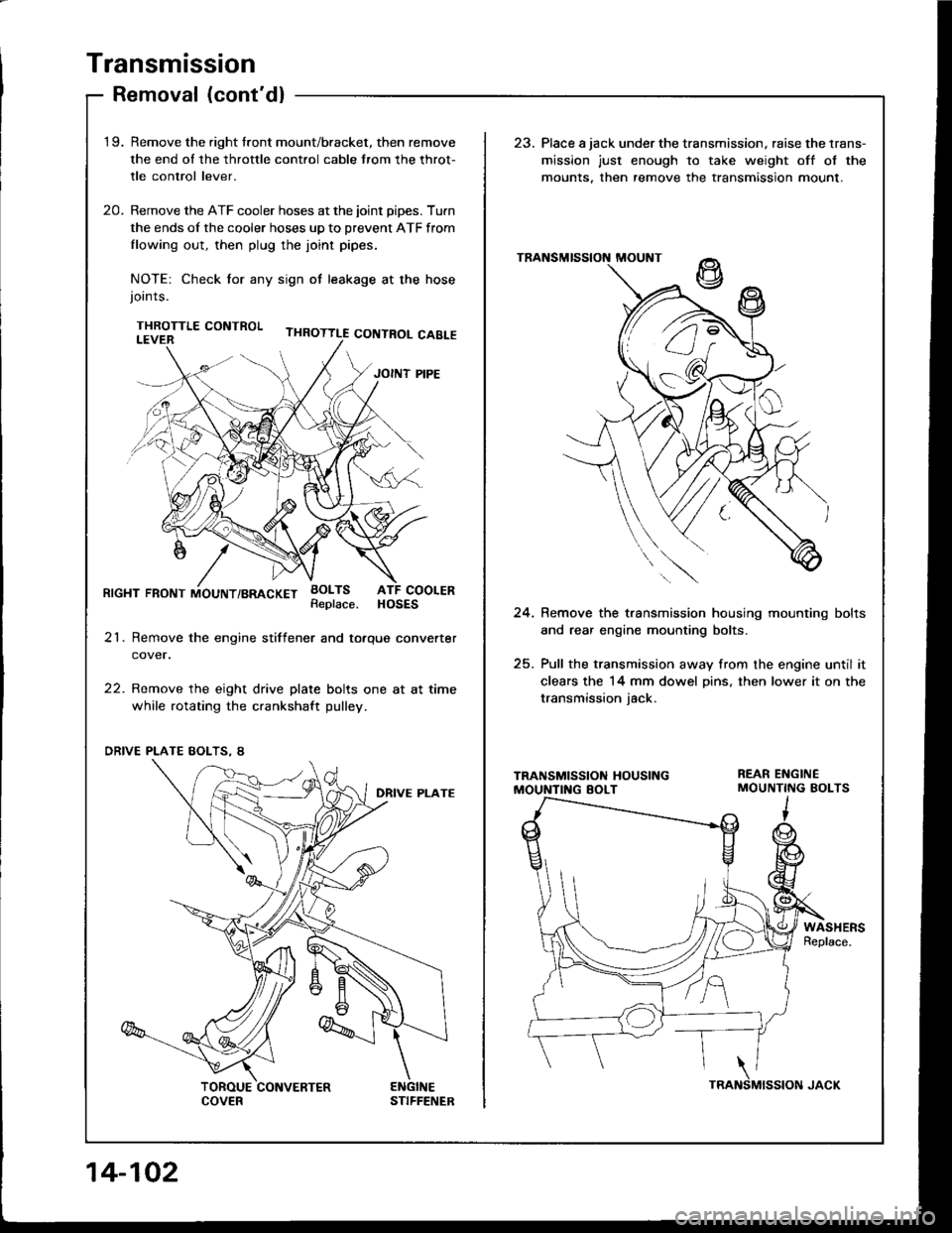
Transmission
Removal (cont'dl
'1 9.Remove the right tront mount/bracket, then remove
the end ol the throttle cont.ol cable trom the throt-
tle control lever.
Remove the ATF cooler hoses at the joint pipes. Turn
the ends of the cooler hoses up to prevent ATF from
flowing out, then plug the joint pipes.
NOTE: Check tor any sign ot leakage at the hosejoints.
THROTTLE CONTROL
23. Place a jack under the transmission, raise the lrans-
mission just enough to take weight off ol the
mounts. then remove the transmission mount.
20.
RrcHT FRoNT iiouNT/BRAcKET BoLTsATF COOLERHOSESReplace.24. Remove the t.ansmission housing mounting bolts
and rear engine mounting bolts.
25. Pull the transmission away from the engine until it
clears the 14 mm dowel Dins, then lower it on the
transmission iack.
21. Remove the engine stiftener and totque converter
cover.
22. Remove the eight drive plate bolts one at at time
while rotating the crankshaft pulley.
WASHERSReplace.
'i z/'l e
" (-J t'
14-102