HONDA INTEGRA 1994 4.G Service Manual
INTEGRA 1994 4.G
HONDA
HONDA
https://www.carmanualsonline.info/img/13/6067/w960_6067-0.png
HONDA INTEGRA 1994 4.G Service Manual
Page 1196 of 1413
lgnition System
lgnition Timing lnspection and
Setting (cont'd)
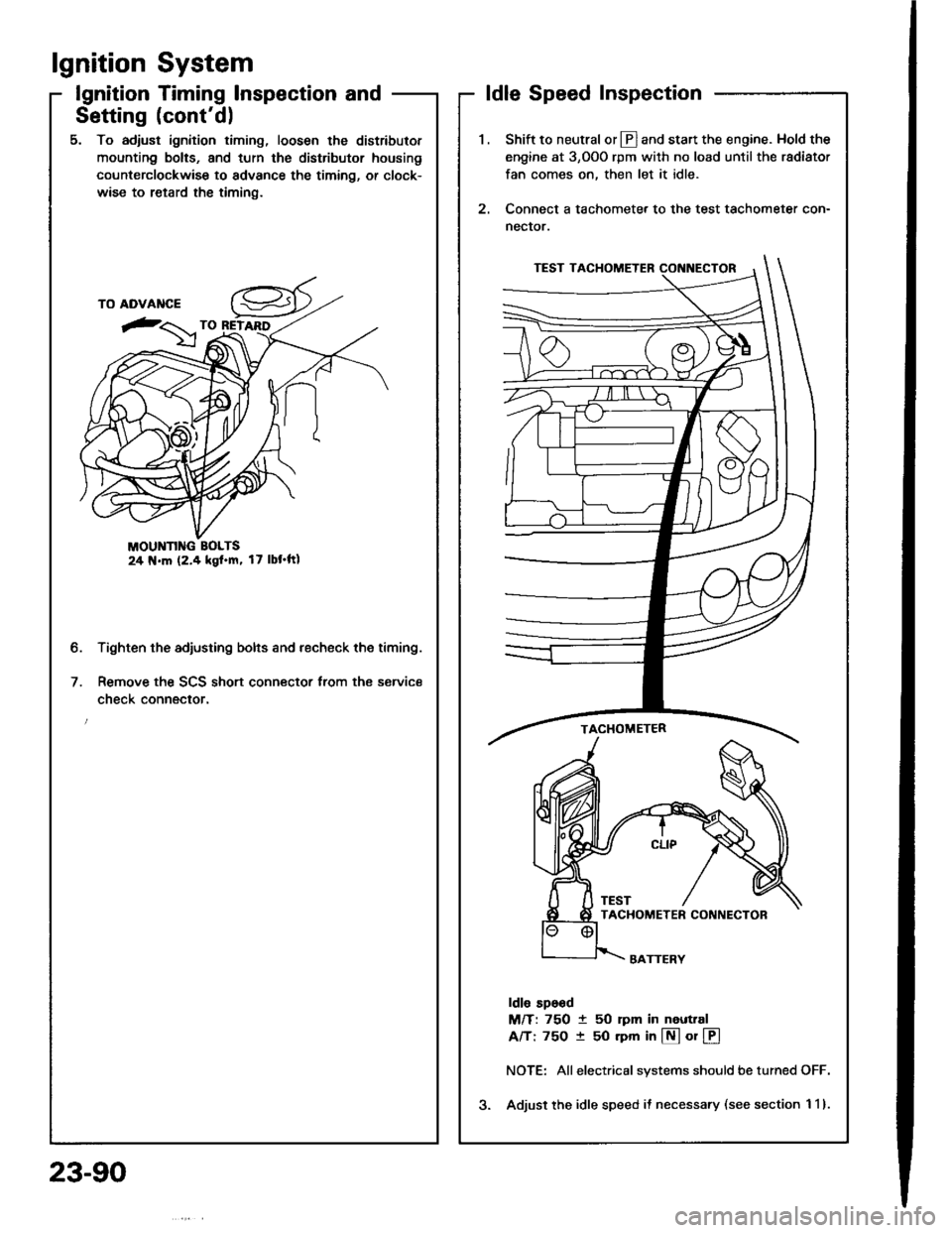
5. To adjust ignition timing, loosen the distributor
mounting bolts, and turn the distributor housing
counterclockwise to advance the timing, or clock-
wise to retard the timing.
MOUNN G BOLTS24 N.m (2.4 kgl.m, 17 lbt'ftl
Tighten the adjusting bolts and recheck the timing.
Remove the SCS short connector trom the service
check connector.
2.
ldle Speed Inspection
Shift to neutral or Ll] and start the engine. Hold the
engine at 3,OOO rpm with no load until the radiator
fan comes on, then let it idle.
Connect a tachometer to the test tachometer con-
nector.
ldle sp6od
M/T: 750 t 50 rpm in neuttal
A/T: 75O t 50 rpm in @ or @
NOTE: Allelectrical systems should be turned OFF.
Adjust the idle speed il necessary (see section 1 1).
b.
23-90
Page 1198 of 1413
lgnition System
Distributor Installation
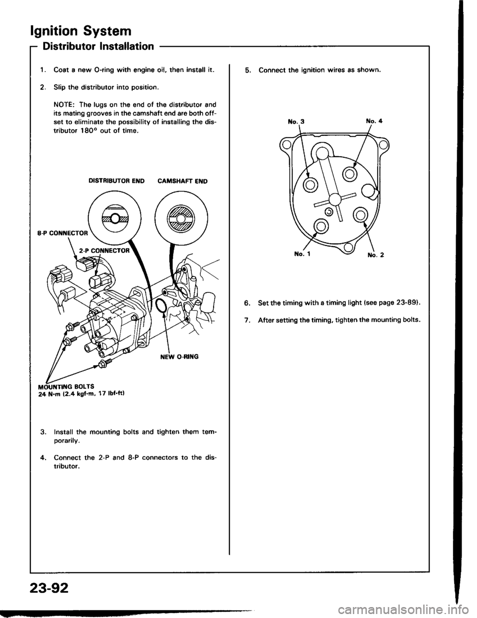
Coat a new O-ring with engine oil, then install it.
Slip the distributor into position.
NOTE: The lugs on the end of the distributor and
its mating grooves in the camshaft end are both off-
set to eliminate the possibility ot installing the dis-
tributor 18Oo out of time.
DISTRIBUTOR END CAMSHAFT END
Install the mounting bolts and tighten them tem-
porarily.
Connect the 2-P and 8-P connectors to the dis-
tributor.
24 N.m (2.4 kgf'm' 17 lbt'ft|
23-92
5. Connect the ignition wires as shown.
Set the timing with a timing light (se€ page 23-89).
After setting the timing, tighten the mounting bolts.
Page 1225 of 1413
Disassembly
NOTE: Handle the terminals and printed circuit boards caretully to avoid damaging them.
ENGINE COOLA]TTTEiIPERATURE {ECT}GAUGEMOUNTING SCREW (x 3)
TAGHOMETER MOUI{TING SCREW (x 3l
SPEEDOMETER MOUNTTNG SCREW tx 4l
. SPEEDOMETER
k)T
-
n
FUEL GAUTest, psgeGE UNIT23-123
Specilication, pa96 23-1 14Troubfeshooting. page 23-1 20. ODOMETERTroubleshooting, page 23-1 20. TRIP METERTroubfeshooting, page 23-1 20
23-119
Page 1228 of 1413

Replacement
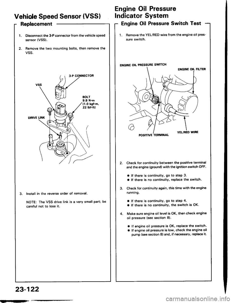
Disconnect the 3-P connector trom the vehicle speed
sensor {VSS).
Remove ihe two mounting bolts, then remove the
VSS.
InstSll in the revsrse order of removal.
NOTE: The VSS drive link is a very small paru
caretul not to lose it.
Engine Oil Pressure
Vehide Speed Sensor (VSSIIndicator System
Engine Oil Pressure Switch Test
1. Remove the YEL/RED wile from the engine oil pres-
sure switch.
ENGI'{E OIL PRESSURE SWITCH
Check tor continuitv between the positive torminal
and the engine {gtound) with the ignhion swhch OFF.
a lf there is continuity, go to step 3.
a lf there is no continuity, replace the switch.
Check for continuity again, this time with th€ engine
runnrng.
a lf there is continuity, go to step 4,
a lf there is no continuity, the switch is OK.
Make sure engine oil level is OK, then check engin€
oil pressure (s€e section 8).
a lf engine oil pressure is OK, replace the switch'
a lf engine oil pressure is low, check the sngine oil
pump (see section 8) and, if necessary, replac€ it.
POSITIVE TERMII{AL
23-122
nlmlliitl
Page 1243 of 1413

Replacement
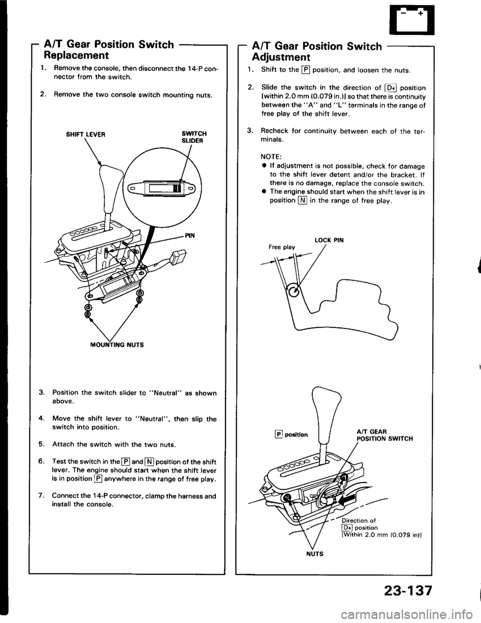
Remove the console, then disconnect the 14-P con-nectof from the switch.
Remove the two console switch mounting nuts.
swtTcH
A/T Gear Position SwitchA/T Gear Position Switch
Adjustment
1. Shift to the ill position, and loosen the nuts.
2. Slide the switch in the direcrion of E position
[within 2.O mm (O.079 in.)l so that there is continuity
between the "A" and "L" terminals in the ranqe of
free plsy oJ the shiJt lever.
3. Recheck for continuity between each ot the ter-
minals.
NOTE:
a lf adiustment is not possible. check for damage
to the shiJt lever detent and/or the bracket. lfthere is no damage, replace the console switch.a The engine should start when the shift lever is inposition LN] in the range of free play.
@ porition
Position the switch slider to "Neutral" as shown
above.
4. Move the shift lever to
switch into position.then slip the
Attach the switch with the two nuts.
Test the switch in the @ and E] position ot the shift
lever. The engine should sta.t when the shift leveris in position p anywhere in the range of free play.
Connect the 14-P connector, clamp the harness andinstall the console.
SHIFT LEVER
LOCK PIN
NUTS
23-137


![HONDA INTEGRA 1994 4.G Service Manual Disassembly
NOTE: Handle the terminals and printed circuit boards caretully to avoid damaging them.
ENGINE COOLA]TTTEiIPERATURE {ECT}GAUGEMOUNTING SCREW (x 3)
TAGHOMETER MOUI{TING SCREW (x 3l
SPEEDOME HONDA INTEGRA 1994 4.G Service Manual Disassembly
NOTE: Handle the terminals and printed circuit boards caretully to avoid damaging them.
ENGINE COOLA]TTTEiIPERATURE {ECT}GAUGEMOUNTING SCREW (x 3)
TAGHOMETER MOUI{TING SCREW (x 3l
SPEEDOME](/img/13/6067/w960_6067-1224.png)

