tow HONDA INTEGRA 1994 4.G Owner's Guide
[x] Cancel search | Manufacturer: HONDA, Model Year: 1994, Model line: INTEGRA, Model: HONDA INTEGRA 1994 4.GPages: 1413, PDF Size: 37.94 MB
Page 335 of 1413
Clutch Master Cylinder
Removal/lnstallation
CAUTION:
a Do not sgill b.ake lluid on the car; it may damags the
painl; it biake fluid does contact tha paint. wash it
otf immediately with water.
a Plug lhe end ot the clutch pips and r€servoil hose with
a shop towel to prsvent blake fluid ttom coming out.
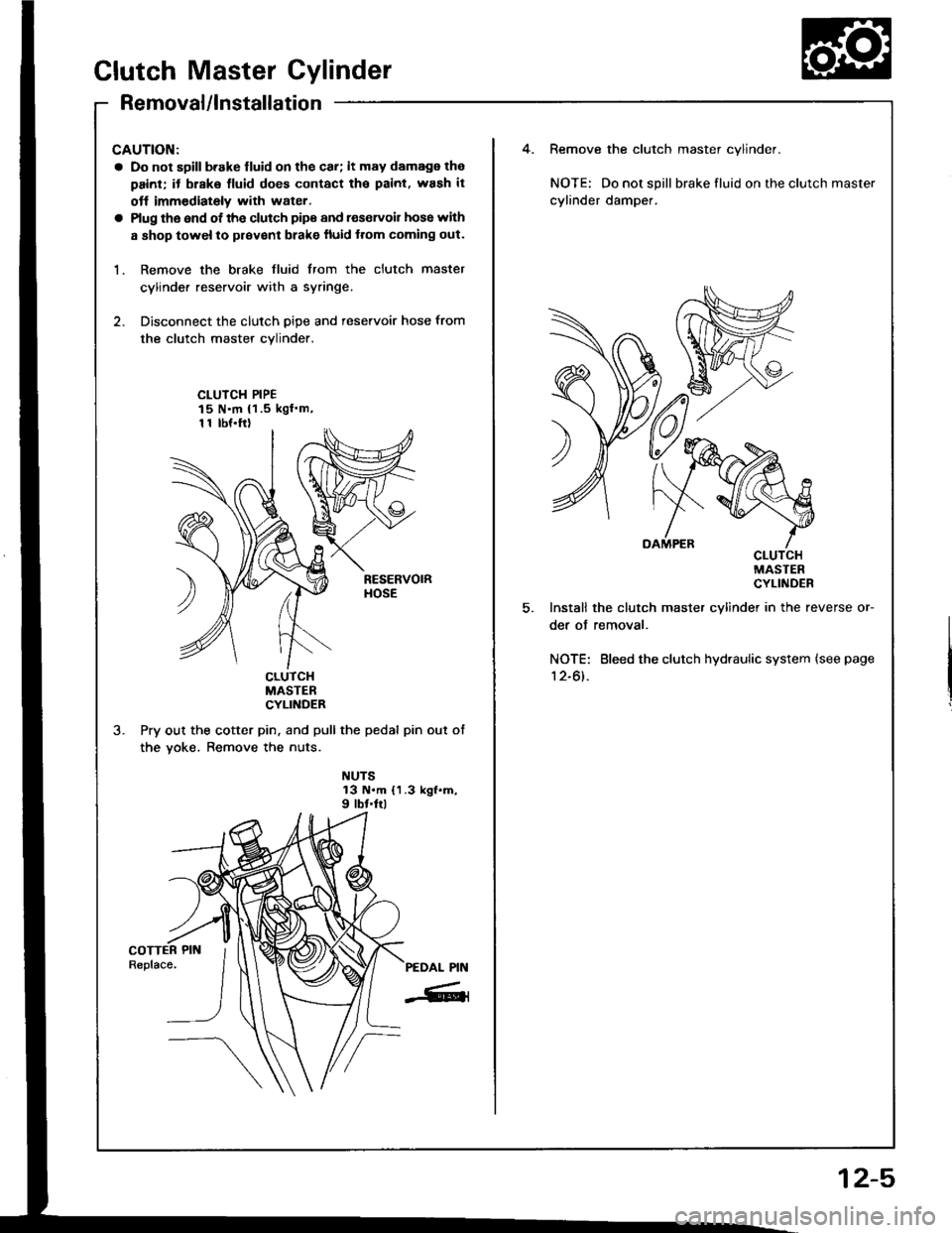
1. Remove the brake fluid from the clutch master
cylinde. reservoir with a syringe.
2. Disconnect the clutch oioe and reservoir hose from
the clutch master cvlinder.
CLUICH PIPE15 N'm {1.5 kgl.m,1 1 tbf.ftl
CLUTCHMASTERCYLINDER
Pry out the cotter pin. and pull the pedal pin out ot
the yoke. Remove the nuts.
NUTS13 N.m {1.3 kgf.m,9 lbt.frl
Remove the clutch master cylinder.
NOTE: Do not spill brake fluid on the
cylinder damper.
OAMPERCLUMAIcYL
Install the clutch master cylinder in
der of removal.
NOTE: Bleed the clutch hydraulic s\
12-61.
clutch master
CLUTCHMASTERCYLINDER
!l rn Ine reverse or-
c system (see page
12-5
Page 382 of 1413
Mainshaft Thrust Clearance
Adjustment (cont'd)
MAINSHAFT
-),.
"7t/'-
'..' .'i'
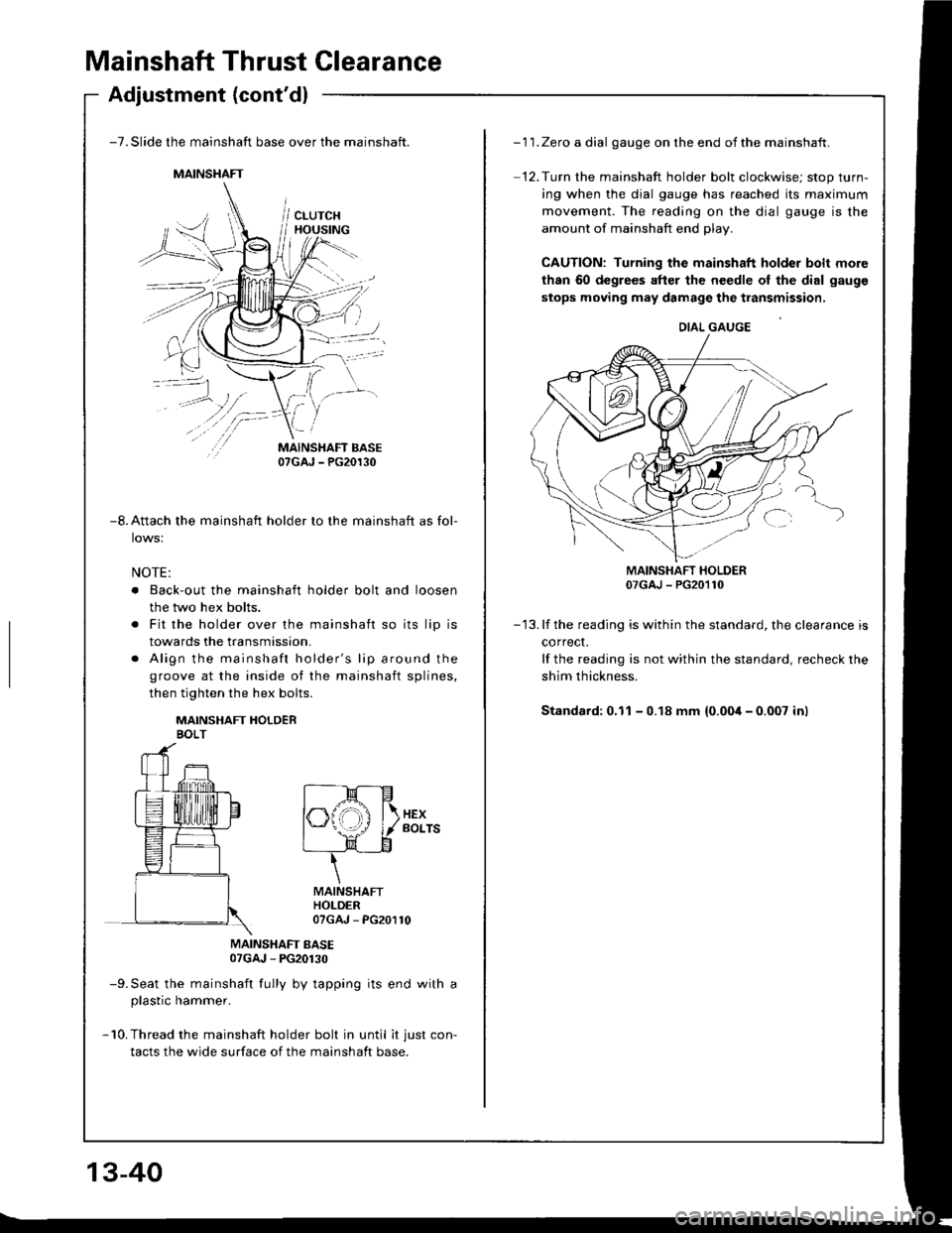
-7. Slide the mainshaft base over the mainshaft.
i.�,
MAINSHAFT BASE07GAJ - PG20130
-8. Attach the mainshaft holder to the mainshaft as fol-
NOTE:
. Back-out the mainshaft holder bolt and loosen
the two hex bolts.
. Fit the holder over the mainshaft so its lip is
towards the transmission.
. Align the mainshaft holder's lip around the
groove at the inside ot the mainshaft splines,
then tighten the hex bolts.
MAINSHAFT HOLOERBOLT
f- t{-c
lnrTh l
ex
| \-_.r' ._/_/ lrl Borrs
L ___E_J
\MAINSHAFTHOLDER07GAJ - PG20110
MAINSHAFT BASE07cAJ _ PG20130
-9.Seat the mainshaft fully by tapping its end with a
plastic hammer.
-10.Thread the mainshaft holder bolt in until it just con-
tacts the wide surface of the mainshaft base.
- 1 1. Zero a dial gauge on the end of the mainshaft.
12.Turn the mainshaft holder bolt clockwise; stop turn-
ing when the dial gauge has reached its maximum
movement. The reading on the dial gauge is the
amount of mainshaft end play.
CAUTION: Turning the mainshaft holder bolt mor€
than 60 degrees after the needle ol the dial gauge
stops moving may damage the transmission,
DIAL GAUGE
MAINSHAFT HOLDER07GAJ - PG201r0
- 13.lf the reading is within the standard, the clearance is
correq.
lf the reading is not within the standard, recheck the
shim thickness.
Standard: 0.11 - 0.18 mm {0.004 - 0.007 in)
\
13-40
Page 428 of 1413
Description
Hydraulic Flow (cont'd)
LEI Position
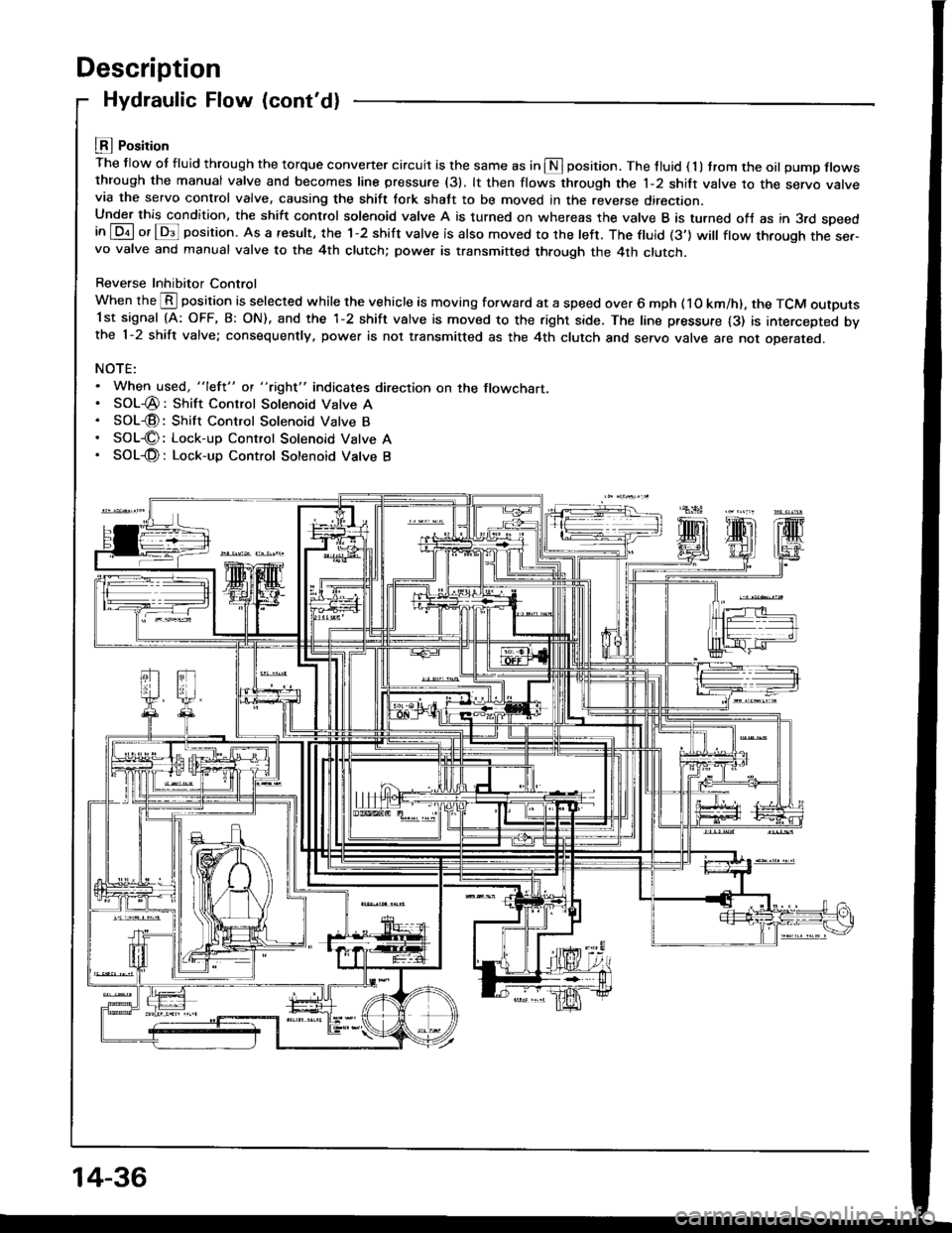
The flow ot fluid through the torque convener circuit is the same as in S position. The tluid ( 1 ) trom the oil pump flowsthrough the manual valve and becomes line pressure (31. lt then flows through the 1-2 shift valve to the servo varvevia the servo control valve, causing the shift tork shatt to be moved in the reverse direction.Under this condition, the shift control solenoid valve A is turned on whereas the valve B is turned ofJ as in 3rd speedin [Dil or lDs]l position. As a result, the 1-2 shift valve is also moved to the left. The ftuid (3'] will ftow through the ser-vo valve and manual valve to the 4th clutch; power is transmitted through the 4th clutch.
Reverse Inhibitor Control
When the @ position is selected while the vehicle is moving forward at a speed over 6 mph ( 1O km/h). the TCM outputs1st signal (A: OFF, B: ON), and the 1-2 shift valve is moved to the right side. The line pressure {3) is intercepted bvthe 1-2 shift valve; consequently, power is not transmitted as the 4th clutch and servo valve are not oDerareo.
NOTE:. When used, "lefl" ot "tight" indicates direction on the flowchart.. SOL-@: Shift Control Solenoid Valve A. SOL€: Shift Control Solenoid Valve B. SOL€: Lock-up Control Solenoid Vatve A. SOL-@: Lock-up Control Sotenoid Vatve B
14-36
Page 430 of 1413
Description
Lock-up System
Lock-up Clutch
1. Operation (clutch on)
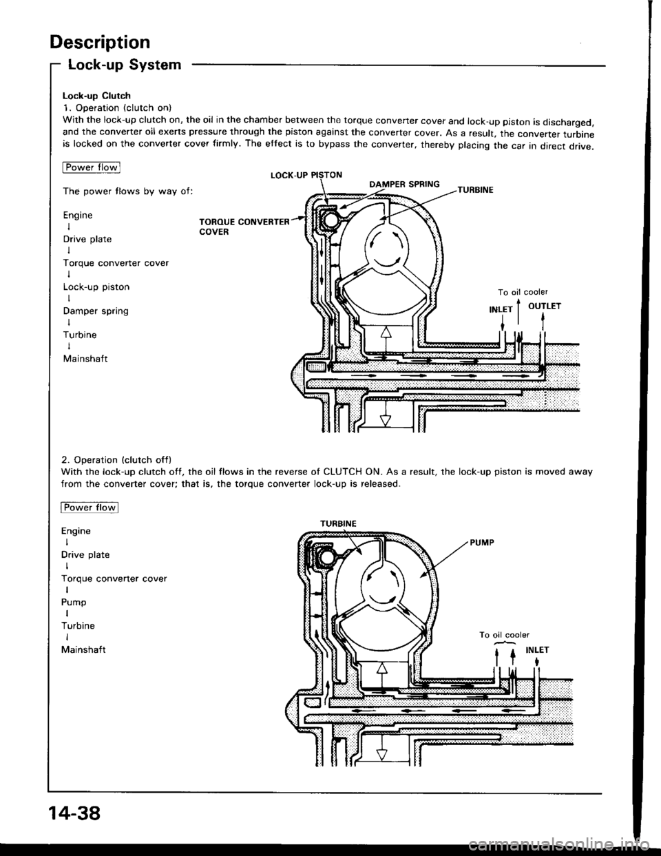
With the lock-up clutch on, the oil in the chamber between the torque convener cover and lock-up piston is discharged,and the converter oil exerts pressure through the piston against the converter cover. As a result, the converter turbineis locked on the converter cover firmly. The etfect is to bypass the converter, thereby placing the car in direct drive.
tpowefJlo-wl
The power tlows by way of:
Engine
I
Drive plate
I
Torque convener cover
I
Lock-up piston
I
Damper spring
I
Turbine
t
Mainshaft
TOROUE CONVERTERCOVER
LOCK-UP
TURBINE
To oil cooler
2. Operation (clutch off)
With the lock-up clutch off, the oil tlows in the reverse of CLUTCH ON. As a result, the lock-up piston is moved away
from the converter cover; that is, the torque converter lock-up is released.
Fowtttowl
Engine
I
Drive plate
I
Torque converter cover
Pump
I
Turbine
I
Mainshaft
OUTLET
t
,\
TURBINE
14-38
Page 507 of 1413
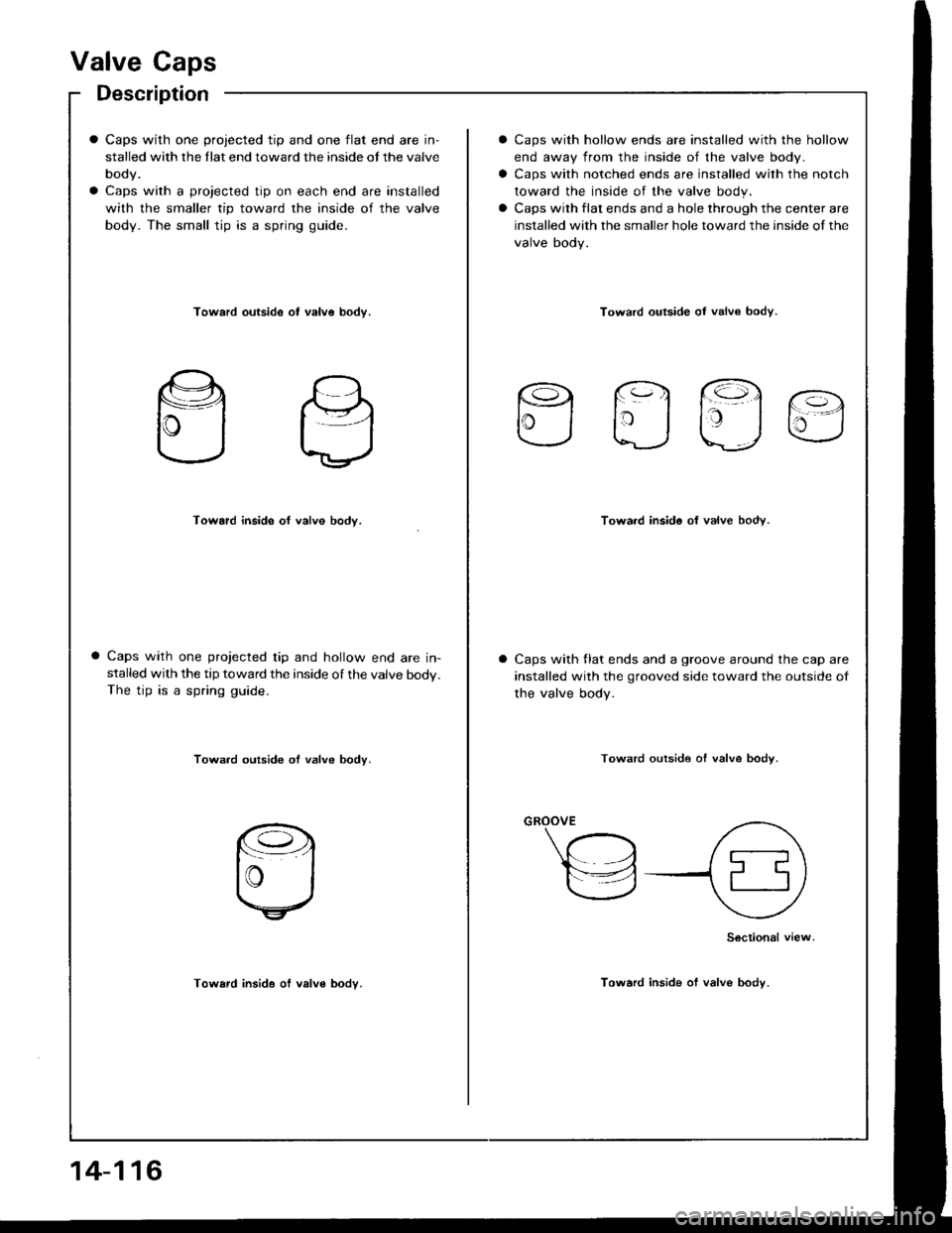
Valve Caps
Description
Caps with one projected tip and one flat end are in-
stalled with the llat end toward the inside ot the valve
body.
Caps with a projected tip on each end are installed
with the smaller tip toward the inside of the valve
body. The small tip is a spring guide.
Caps with hollow ends are installed with the hollow
end away from the inside of the valve body.
Caps with notched ends are installed with the notch
toward the inside of the valve body.
Caps with flat ends and a hole through the center are
installed with the smaller hole toward the inside of the
valve body.
Toward outside ot valv6 bodv.Toward outside oI valv€ bodv.
rq fq1 @.
lrj taj u
Toward inside of valve body.Towa.d inside of valve body.
Caps with one projected tip and hollow end are in-stalled with the tip toward the inside of the valve body.The tip is a spring guide.
Caps with llat ends and a groove around the cap are
installed with the grooved side toward the outside of
the valve body.
Towa.d outside ot valve body.Toward outside of valve bodv.
Toward inside of valve body.
Sectional view
Toward inside of valve body.
14-116
Page 524 of 1413
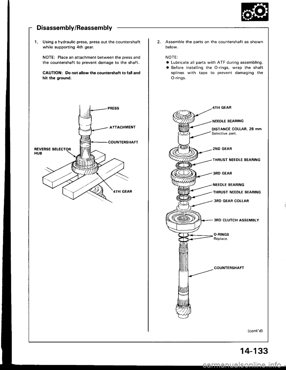
Disassembly/Reassembly
1, Using a hydraulic press, press out the countershatt
while supponing 4th gear.
NOTE: Place an attachment between the press and
the countershatt to prevent damage to the shaft.
CAUTION: Do not allow the countershaft to lall and
hit the ground.
2.Assemble the parts on the countershaft as shown
oetow.
NOTE:
a Lubricate all parts with ATF during assembling.
a Before installing the O-rings, wrap the shalt
splines with tape to prevent damaging the
O-rings.
4TH GEAR
NEEDLE BEARING
DISTANCE COLLAR. 29 mm
Selective part.
2ND GEAR
THRUST NEEDLE BEARING
3RD GEAR
NEEDLE BEARING
THRUST NEEDLE BEARING
3RD GEAR COLLAR
3RD CLUTCH ASSEMBLY
O-RINGSReplace.
COUNTERSHAFT
{cont'd)
Page 536 of 1413
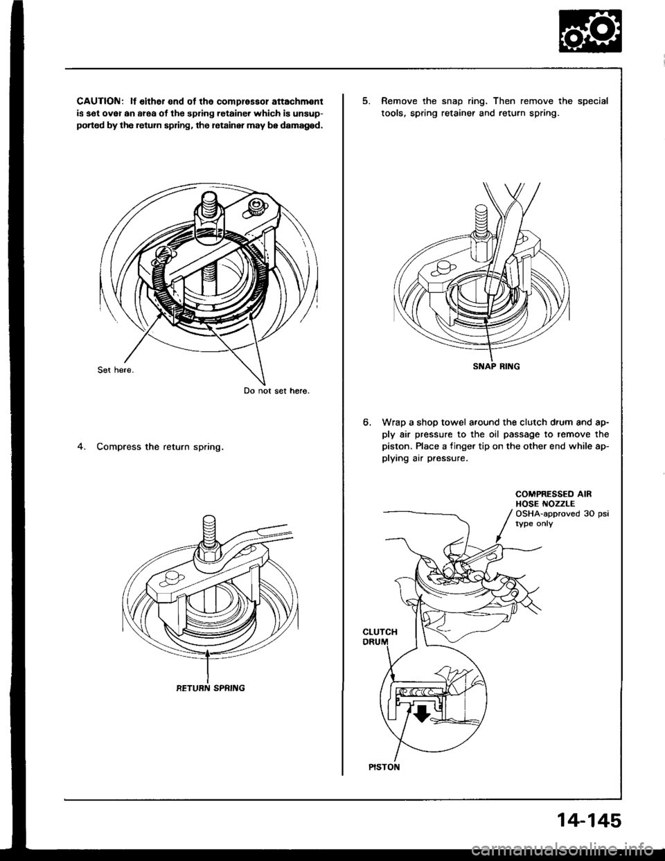
CAUTION: lf either end ot the comprassol attachm€nt
is sel ovsl an araa ol the spdng retaine. which is unsup-
ported by the retum spring. the letainer may be damag6d,
4. Compress the return spring.
Do not set horo.
RETURN SPRING
5.Remove the snap ring. Then remove the special
tools, spring retainer and return spring.
Wrap a shop towel around the clutch drum and ap-
ply air pressure to the oil passage to remove the
piston. Place a finger tip on the other end while ap-
plying air p.essure.
6.
COMPRESSED AIRHOSE NOZZLEOSHA-approved 30 psirype onry
CLUTCH
S AP RING
PISTON
14-145
Page 539 of 1413
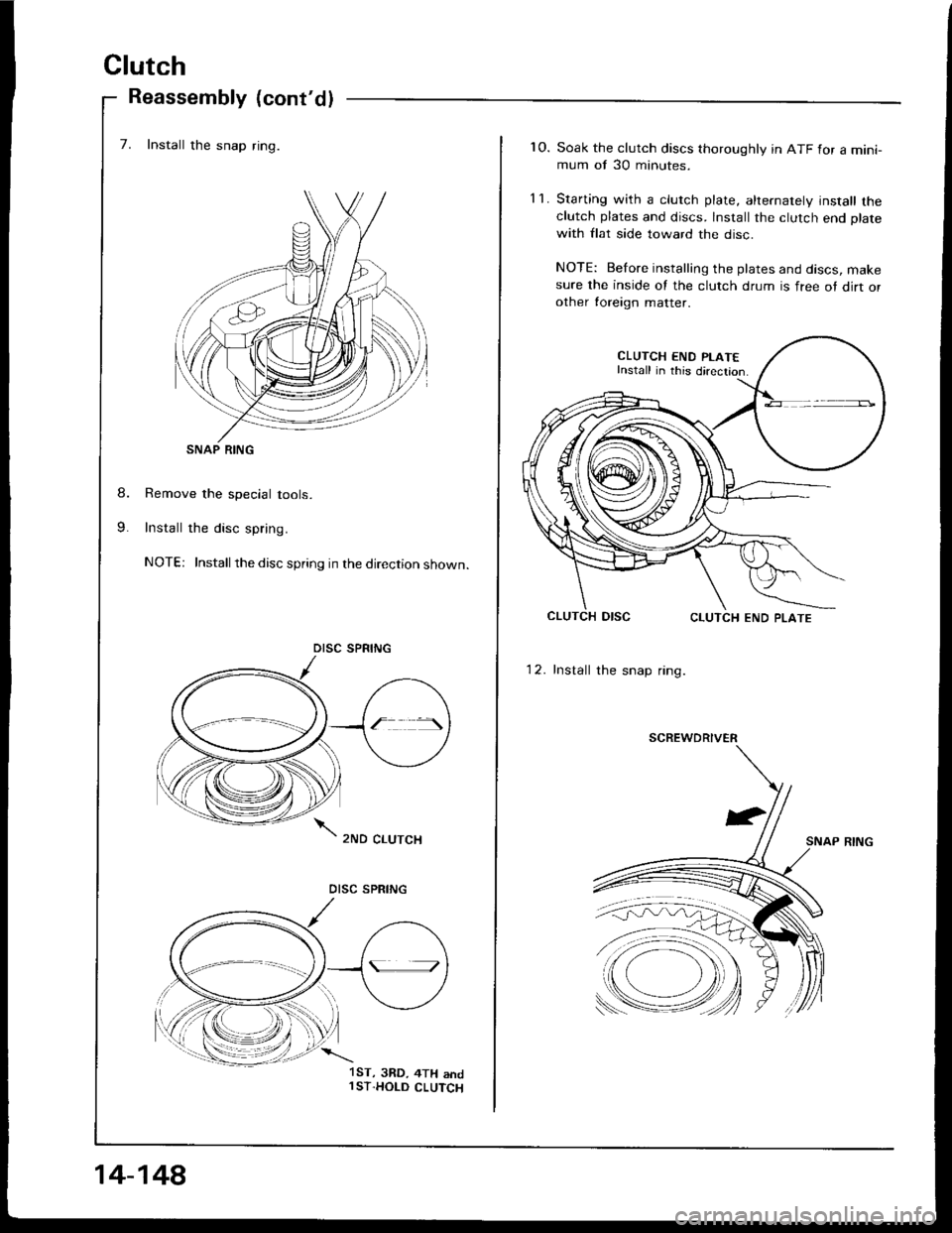
Clutch
Reassembly (cont'd)
7. Install the snap ring.
Remove the special tools.
Install the disc spring.
NOTE: Installthe disc spring in the direction shown.
SNAP RING
DISC SPRING
.\
):ll
14-148
1ST, 3RD, 4TH andl ST.HOLD CLUTCH
1O. Soak the clutch discs thoroughly in ATF for a mini-mum of 30 minutes.
11. Starting with a clutch plate, alrernately install theclutch plates and discs. Install the clutch end plate
with flat side toward the disc.
NOTE: Before insralling the plates and discs, makesure the inside of the clutch drum is free ot dirt orother toreign matter.
CLUTCH END PLAT€Install in this direction
12. Install the snap ring.
SNAP RING
SCREWDRIVER
Page 598 of 1413
Driveshafts
Disassembly (cont'd)
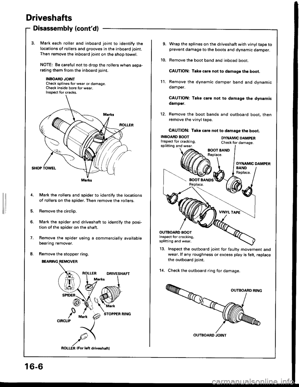
3, Mark each roller and inboard joint to identify the
locations of rollers and grooves in the inboard joint.
Then remove the inboard joint on the shop towel.
NOTE: Be careful not to drop the rollers when sepa-rating them from the inboard joint.
INBOARD JOINTCheck splines tor w6ar or damage.Ch€ck inside bore for wear.Inspect tor cracks.
Mark the rollers and spider to identify the locations
of rollers on the spider. Then remove the rollers.
Remove the circlip.
Mark the spider and driveshaft to identify the posi-
tion of the spider on the shaft.
Remove the spider using a commercially available
bearing remover.
Remove the stopper ring.
BEARING
STOPPER RING
Marka
o.
,'0CIRCLIP
16-6
ROLI-€R lFor loft ddvcshrfrl
9. Wrap the splines on the driveshaft with vinyltape toprevent damage to the boots and dynamic damper.
10. Remove the boot band and inboad boot.
CAUTION: Take car. not to damage th€ boot.
11. Remove the dynamic damper band and dynamicdamoer.
CAUTION: Tako cars not to damage the dynamicdamper.
12. Remove the boot bands and outboard boot, thenremove the vinyltape.
CAUTION: Take csre nol to damage tho boot.
INBOARD BOOTInspect lor cracking,splitting and wear.
DYNAMIC DAMPERCheck tor damage.
DYNAMIC DAMPER
13. Inspect the outboard joint for faulty movement andwear. lf any roughness or excess play is felt, replace
the outboard joint.
14. Check the outboard ring for damage.
OUTBOARD BOOTlnspect for cracking,splining and wear.
OUTBOARD JOINT
Page 601 of 1413
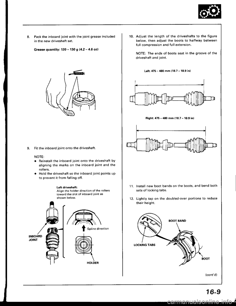
8.Pack the inboard joint with the ioint grease included
in the new driveshaft set.
Grease quantity; 120 - 130 g 11.2 - 4.6 ozl
9. Fit the inboard joint onto the driveshaft.
NOTE;
. Reinstall the inboard joint onto the driveshaft by
aligning the marks on the inboard ioint and the
rollers.
. Hold the driveshaft so the inboard joint points up
to prevent it from falling off.
Left drivoshaft:Align the holder direction of the rollers
toward the slot ot inboard joint as
INBOARDJOINT
/,.-:--\ \
I sotine di,ection
A\
{(@}
HOLDER
10.Adjust the length of the driveshafts to the figure
below. then adjust the boots to halfway between
full compression and full extension.
NOTE: The ends of boots seat in the groove of the
driveshaft and joint.
Left: 475 - 480 mm {18.7 - 18.9 inl
Right: 475 - 480 mm (18.7 - 18.9 inl
lnstall new boot bands on the boots, and bend both
sets of locking tabs.
Lightly rap on the doubled-over portions to reduce
their height.
{cont'd)
11.
16-9