tow HONDA INTEGRA 1994 4.G Repair Manual
[x] Cancel search | Manufacturer: HONDA, Model Year: 1994, Model line: INTEGRA, Model: HONDA INTEGRA 1994 4.GPages: 1413, PDF Size: 37.94 MB
Page 921 of 1413
Mirrors
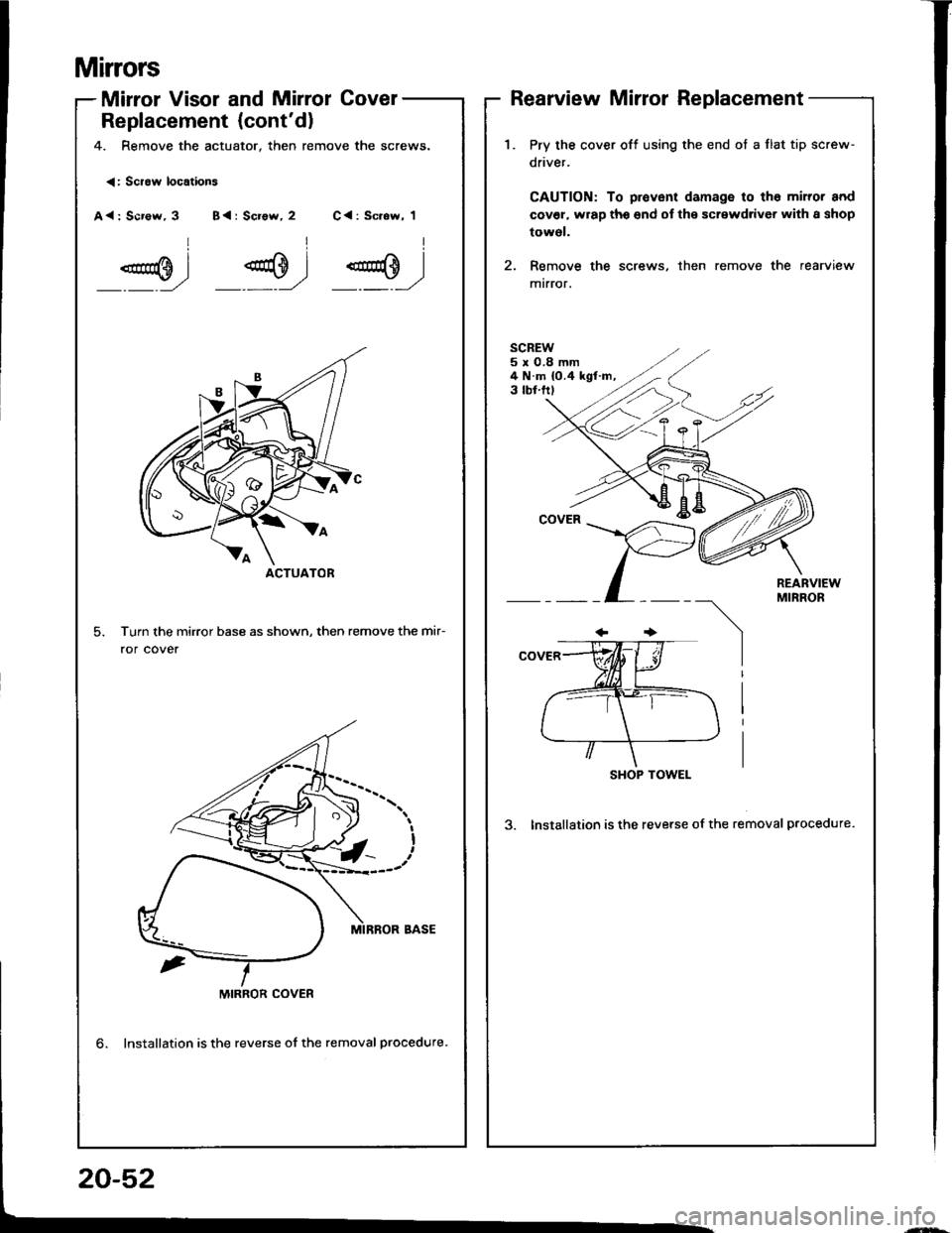
Mirror Visor and Mirrol Covel
Replacement {cont'd)
4. Remove the actuator, then remove the screws.
Rearview Mirror Replacement
<: Scraw locations
A<: Scr€w, 3 B{: Screw, 2 C<: Sc.ew, 1
Turn the mirror base as shown, then remove the mir-
ror cover
ACTUATOR
1.Pry the cover off using the end ot a flat tip screw-
driver.
CAUTION: To provent damage to tho miror and
cov€l, wrap tho end of the screwdriver with I shop
towol.
Remove the screws, then remove the rearview
mtrror.
SCREW5x0.8mm4 N.m {0.4 kgf.m,3 tbf.ftl
REARVIEWMIRROR
SHOP TOWEL
3. Installation is the reverse of the removal procedure.
MIRROR COVER
lnstallation is the reverse of the removal procedure.
20-52
Page 928 of 1413
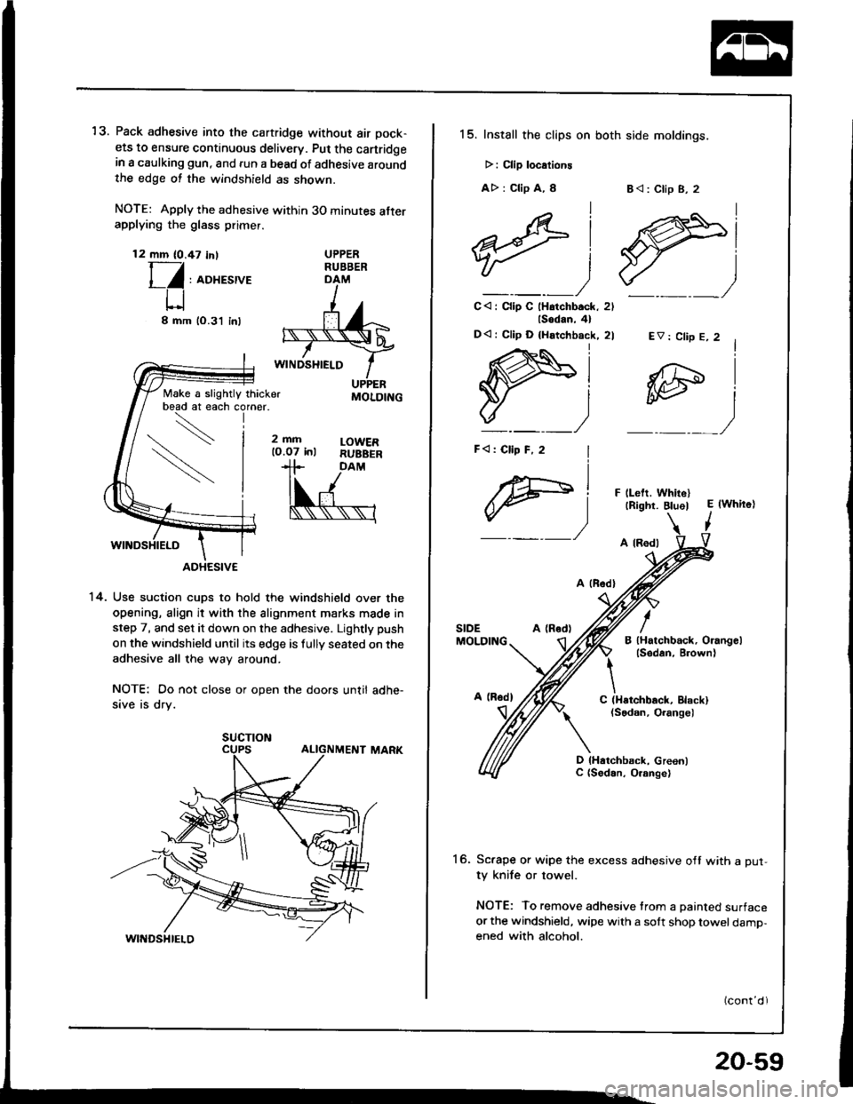
13. Pack adhesive into the cartridge without air pock-
ets to ensure continuous delivery. Put the canridgein a caulking gun, and run a bead ot adhesive aroundthe edge ot the windshield as shown.
NOTE: Apply the adhesive within 30 minutes afterapplying the glass primer.
12 mm (0.47 in,T-/
l_/ : roxesrve
U8mm
Make a slightly thicker
DAM
'14. Use suction cups to hold the windshield over the
opening, align it with the alignment marks made in
step 7, and set it down on the adhesive. Lightly push
on the windshield until its edge is fully seated on the
adhesive all the way around.
NOTE: Do not close or open the doors until adhe-
sive is dry.
UPPERRUBBER
lO.3'l inl
2mfilO.O7 inlLOWERRUBBEB
MOLDING
SUCTION
15. Install the clips on both side moldings.
>: Clip localione
A> : Clip A, I
lsodan,4l
D<: Cllp D {Hatchback, 2l
I
F)
B<: Clip B, 2
lAi
ffil"___)
C<: Clip C lHatchback, 2l_)
EV: Clip E, 2
F llelt. WhitellRight. BluelE lwhite)
I
A (Rod)
A lRodl
B lHatchback, Orangellsedan, B.own)
/SIDEMOLDING
It\C (Hstchback, Elack)(Sodan, Orangel
D lHatchback, Green)C (Sodan, O.ange)
16. Sc.ape or wipe the excess adhesive off with a Dut-ty knife or towel.
NOTE: To remove adhesive trom a painted surface
or the windshield, wipe with a solt shop towel damp-ened with alcohol.
20-59
Page 934 of 1413
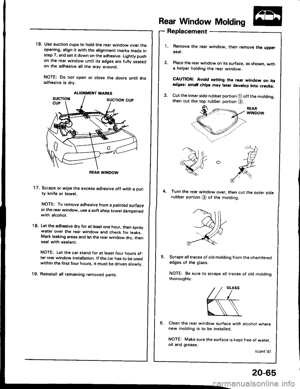
ALIGNMEI{T MARKS
REAR WINDOW
16. Use suction cups to hold the rear window over theopening, align it with the alignment marks made instep 7, and set it down on the adhesive. Lightly pushon the rear window until its edges are fulty seatedon the adhesive all the way around,
NOTE: Do not open or close the doors until theadhesive is drv.
17. Scrape or wipe the sxcess adhesive otf with a Dut-ty knife or towel,
NOTE: To remove adhesive lrcm a painted swfaceor the rear window, use a soft shop towel damDenedwith alcohol.
1 8. Let the adhesivs dry tor at least one hour, then spraywatgr over the raar window and check tor leaks.Mark leaking areas and let the rear window dry, thenseal with sealant.
NOTE: Let the car stand for at least tour hours al_ter rear window installation. lf the car has to be usedwithin the first four hours, it must be driven slowlv.
19. Reinstall all remaining removed parts.
Rear Window Molding
Replacement
1. Remove the rear window, then remove the uppGrseal.
2. Place the rear window on its surface, as shown, witha helper holding the rear window.
CAUTION: Avold setting the rea? ryindow on h!odgos: small chips may latol dovolop into cracka.
3. Cut the inner side rubber portion O olf the molding,then cut the top rubber portion @.
REARwtNDow
4. Turn the rear window over, then cut the outer siderubber portion @ of the motding.
5. Scrape all traces of old molding trom the chamterededges of the glass.
NOTE: Be sure to scrape all traces of old moldingthoroughly.
6. Clean the rear window su.tace with alcohol wherenew molding is to be installed.
NOTE: Make sure the su.face is kept tree of waler,oil and grease.
{cont'dl
20-65
Page 941 of 1413
Rear Wndow
Installation (cont'dl
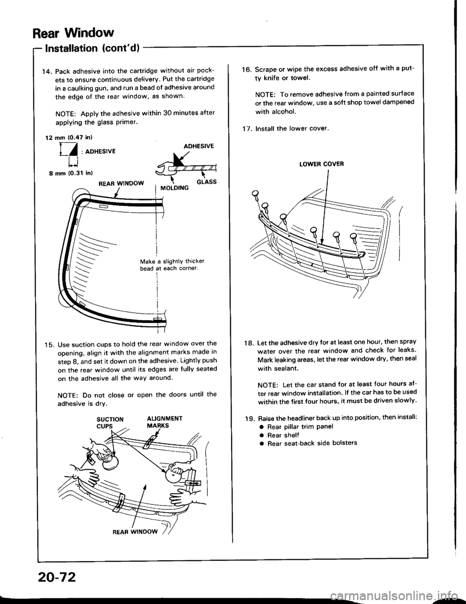
14. Pack adhesive into the cartridge without air pock-
ets to ensure continuous delivery. Put the cartridge
in a caulking gun, and run a bead of adhesive around
the edge oI the rear window, as shown.
NOTE: Apply the adhesive within 30 minutes after
applying the glass Primer.
12 mm (O.47 inl
[/ , aoxesrveADHESIVE
^X-"--"-,s-_T--r-
cr-rssI MOLOING
t-l
8 mm (o,31 inl
15.
REAR WINDOW
Use suction cups to hold the rear window over the
opening, align it with the alignment marks made in
step 8, and set it down on the adhesive Lightly push
on the rear window until its edges are fully seated
on the adhesive all the way around.
NOTE: Do not close or open the doors until the
adhesive is drv.
SUCTION ALIGNMENT
20-72
.-
16. Scrape or wipe the excess adhesive off with a put-
ty knife or towel.
NOTE: To remove adhesive from a painted surtace
or the rear window, use a soft shop towel dampened
with alcohol.
17. Install the lower cover.
'18. Let the adhesive dry for at least one hour, then spray
water over the rear window and check Jor leaks'
Mark leaking areas, let the rear window dry, then seal
with sealant.
NOTE: Let the car stand Jo. at least four hours af-
ter rear window installation, lf the car has to be used
within the tirst tour hours, it must be driven slowly'
19. Raise the headliner back up into position, then install:
a Rear pillar t.im Panela Rear shelf
a Rear seat-back side bolstels
Page 945 of 1413
Ouarter Glass
SIOE SPACER
ADHESIVETAPE A
Replacement (cont'd)
1 2. Thoroughly mix the adhesive and hardener together
on a glass or metal plate with a putty knife.
NOTE:
a Clean the plate with a sponge and alcohol before
mixing.
a Follow the instructions that came with the
adhesive.
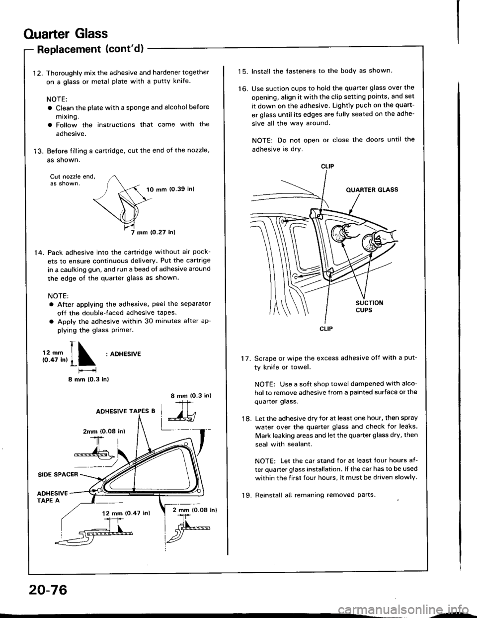
13. Before tilling a cartridge, cut the end of the nozzle,
as shown.
Cut nozzle end,as shown.10 mm 10.39 in)
7 mm {0.27 inl
14. Pack adhesive into the cartridge without air pock-
ets to ensure continuous delivery. Put the cartrige
in a caulking gun, and run a bead of adhesive around
the edge of the quarter glass as shown.
NOTE:
a After applying the adhesive, peel the separator
off the double-faced adhesive tapes.
a Apply the adhesive within 30 minutes after ap-
plying the glass Primer.
t1;T,,1 :ADt'�Es'�vE
I mm 10.3 in)
8 mm lO.3 in)
IJ,
L_-_2mm {0.08-1r
*-{6
AOHESIVE TAPES 8
20-76
'12 mm (0.47 inl2 mm lO.O8 in)
--
t5.Install the fasteners to the body as shown.
Use suction cups to hold the quarter glass over the
opening, align it with the clip setting points, and set
it down on the adhesive. Lightly puch on the quart-
er glass until its edges are tully seated on the adhe-
sive all the way around.
NOTE: Do not open or close the doors until the
adhesive is dry.
to.
17. Scrape or wipe the excess adhesive off with a put-
ty knile or towel,
NOTE: Use a soft shop towel dampened with alco-
hol to remove adhesive from a painted surface or the
quarler glass.
18. Let the adhesive dry for at least one hour, then spray
water over the quarter glass and check for leaks'
Mark leaking areas and let the quarter glass dry, then
seal with sealant.
NOTE: Let the car stand for at least tour hours at-
ter quarter glass installation. lf the car has to be used
within the f irst four hours, it must be driven slowly.
'19. Reinstall all remaning removed parts.
Page 952 of 1413
Opening Drag Check
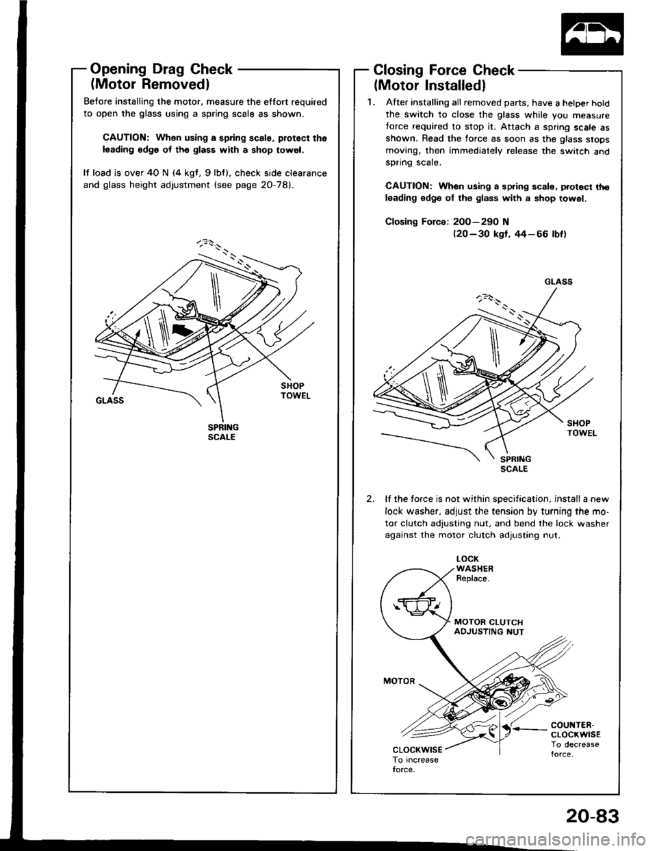
(Motor Removedl
Betore installing the motor, measure the etfort required
to open the glass using a spring scale as shown.
CAUTION: When using a spring scale, protoct the
leading edg6 ot th€ glass with a shop towel.
lf load is over 40 N (4 kgt, 9lbf). check side clearance
and glass height adjustment (see page 2O-78).
Closing Force Check
(Motor Installedl
1. After installing all removed parts, have a hetper hotd
the switch to close the glass while you measure
torce required to stop it. Attach a spring scale asshown. Read the force as soon as the glass siops
moving, then immediately release the switch andspnng scare.
CAUTION: When using a spring scale, protoct tho
leading odge ol th€ glass with a shop towel.
200-290 N(20 - 30 kgf, rt4- 66 lbf)
lf the force is not within specification, install a new
lock washer, adjust the tension by turning the mo-
tor clutch adjusting nut, and bend the lock washer
against the motor clutch adjusting nut.
LOCKWASHERReplace.
'r coul{TER-cLocKwrsETo decrease
GLASS
\
20-83
Page 959 of 1413
Moonroof
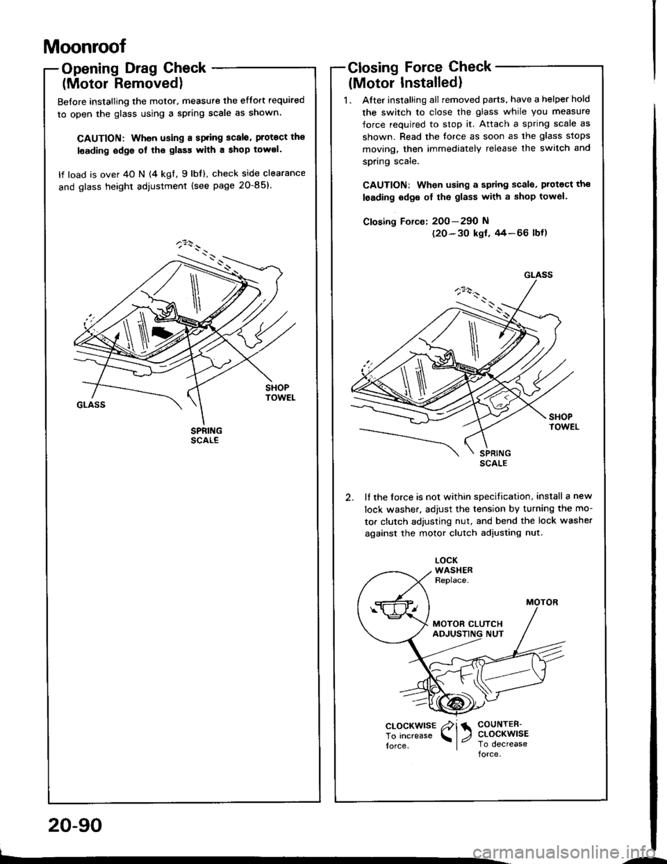
Opening Drag Check
(Motor Removed)
Before installing the motor. measure the effort required
to open the glass using a spring scale as shown
CAUTION: Whon using a spring scalo. protoct the
l€ading odge ol the glass with a shop tow€I.
lf load is over 40 N (4 kgl, 9lbt), check side clearance
and glass height adiustment (see page 20-85)'
Closing Force Check
lMotor Installed)
1. After installing all removed parts, have a helper hold
the switch to close the glass while you measure
force required to stop it. Attach a spring scale as
shown. Read the torce as soon as the glass stops
moving, then immediately release the switch and
spring scale.
CAUTION: When using a sp ng scala. protect th€
leading odge ol the glass with a shop towel'
Closing Force: 200-290 N
120-30 ksf. 44-66 lbf)
lf the lorce is not within specification, install a new
lock washer. adjust the tension by turnang the mo-
tor clutch adjusting nut, and bend the lock washe.
against the motor clutch adjusting nut.
GLASS
\
clocKwlsE /i 1 coutren-
To increase l, ctocKwlsE
torce, I Io decreaseforce
L.
20-90
--
Page 969 of 1413
Headliner
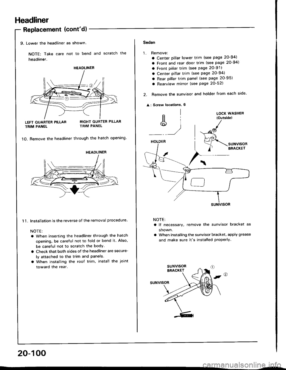
9, Lower the headliner as shown.
NOTE: Take care not to bend and scratch the
headliner.
Replacement {cont'd)
LEFT OUARTER PILLAR
TRIM PANEL
11.
RIGHT OURTER PILLARTRIM PANEL
1O. Bemove the headliner through the hatch opening'
Installation is the reverse of the removal procedure.
NOTE:
a When inserting the headliner through the hatch
opening, be careful not to fold or bend it. Also,
be careful not to scratch the bodY.
a Check that both sides of the headliner are secure-
ly attached to the trim and Panels.
a When installing the roof trim, install the Joint
toward the rear.
20-100
HEADLINER
HEADLINER
Sodan
'1.Remove:
a Center Dillar lower trim (see page 20-94)
a Front and rear door trim lsee page 20-94)
a Front pillar trim (see page 2O-9 .
a Center pillar trim (see page 20-94)
a Rear pillar trim panel (see page 20 95)
a Rearview mirror (see Page 20-521
Remove the sunvisor and holder from each side
: Screw locationS, 6
2.
^l
s,1
LOCK WASHER
loutsidel
HOLDER
/
$-.unu,"o"
/' BRACKET
NOTE:
a lf necessary, remove the sunvisor bracket as
shown.
a When installing the sunvisor bracket, apply grease
and make sure it's installed properly.
,@
suNvrsoR
Page 971 of 1413
Headliner
Replacement {cont'd)
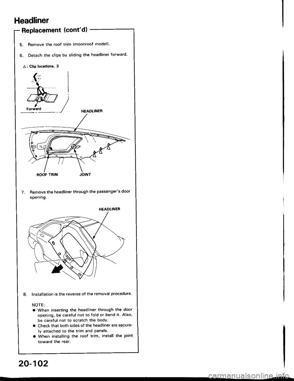
5. Remove the .ool trim (moonroof modell.
6. Detach the clips by sliding the headliner forward.
A : Clip locations, 3
HEADLINER
Remove the headliner through the passenger's door
opening.
lnstallation is the reverse ot the removal procedure
NOTE:
a When inserting the headliner through the door
opening. be careful not to fold or bend it. Also,
be careful not to scratch the body
a Check that both sides ot the headliner are secure-
ly attached to the trim and Panels.
a When installing the roof trim, install the joint
toward the rear.
)
HEADLINER
20-102
Page 991 of 1413
Seat Belts
lnspection
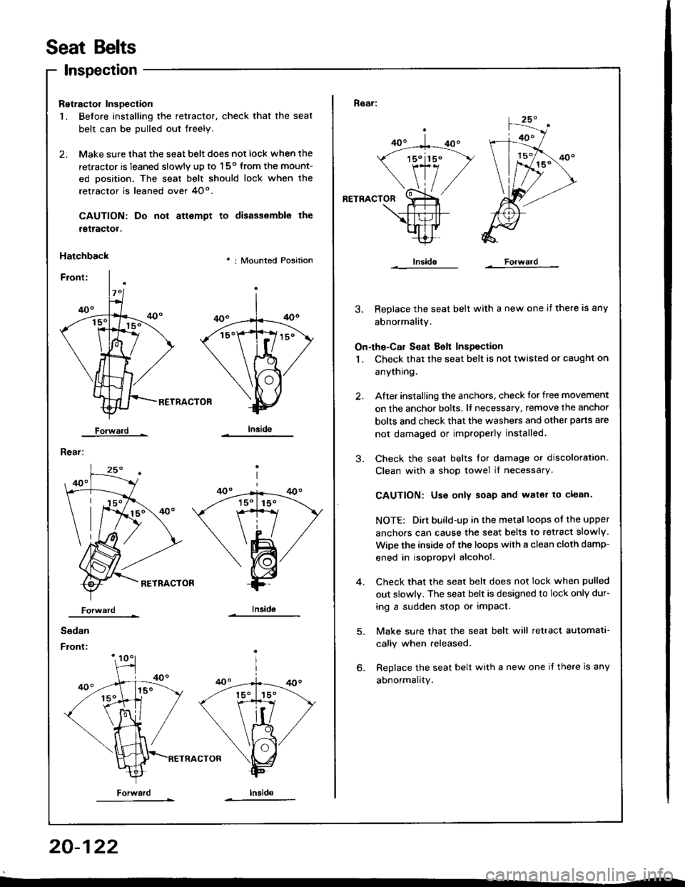
Retractol InsDection
1. Before installing the retractor, check that the seat
belt can be pulled out freely.
2. Make sure that the seat belt does not lock when the
retractor is leaned slowly up to 150 from the mount-
ed oosition. The seal belt should lock when the
retractor is leaned over 4O".
CAUTION: Do
tgtractol.
Hatchback
Forwald -
Rear:
not attempt to disassemble the
' : Mounted Position
RETRACTOB
Iniid6
Sedan
Front:
Forwardlnsido
Forward
Rear:
RETRACTOR
3. Replace the seat belt with a new one if there is any
abnormality.
On-the-Cal S€at Belt Inspection
1 . Check that the seat belt is not twisted or caught on
anythrng.
After installing the anchors, check lor free movement
on the anchor bolts. lf necessary, remove the anchor
bolts and check that the washers and other pans are
not damaged or improperly installed.
Check the seat belts for damage or discoloration.
Clean with a shop towel iI necessary.
CAUTION: Use only soap and water to clean.
NOTE: Dirt build-up in the metal loops of the upper
anchors can cause the seat belts to retract slowly.
WiDe the inside of the loops with a clean cloth damp-
ened in isopropyl alcohol.
Check that the seat belt does not lock when pulled
out slowly. The seat belt is designed to lock only dur-
ing a sudden stop or impact.
Make sure that the seat belt will retract automata-
cally when released.
Replace the seat belt with a new one it there is any
abnormality.
2.
3.
4.
20-122