tow HONDA INTEGRA 1994 4.G Repair Manual
[x] Cancel search | Manufacturer: HONDA, Model Year: 1994, Model line: INTEGRA, Model: HONDA INTEGRA 1994 4.GPages: 1413, PDF Size: 37.94 MB
Page 999 of 1413
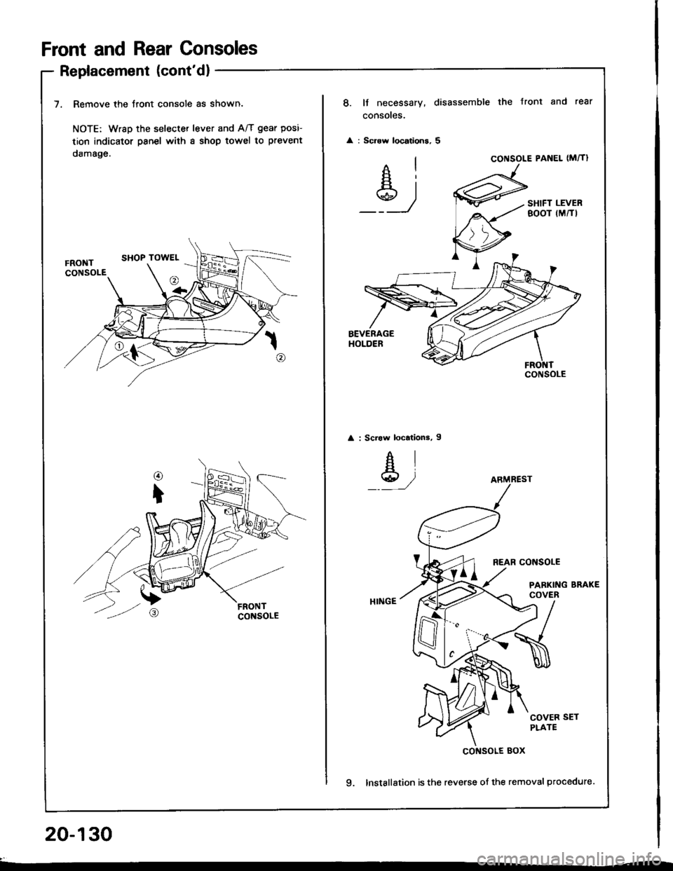
Front and Rear Consoles
Replacement (cont'd)
7. Remove the Jront console as shown.
NOTE: Wrsp the selecter lever and A/T gear posi-
tion indicator psnel with a shop towel to prevent
damage.
20-130
8. It necessary, disassemble the Jront and rear
consoles.
: Scrow locations, 5
Ai
_Y_)
CONSOLE PANEL (M�TI
SHIFT LEVERBOOT (M/TI
: Scraw locations, I
AI
Y,/
REAR CONSOLE
PARKING BRAKECOVER
COVER SETPLATE
9. Installation is the reverse of the removal procedure.
CONSOLE
ARMREST
cof{solE Box
Page 1006 of 1413
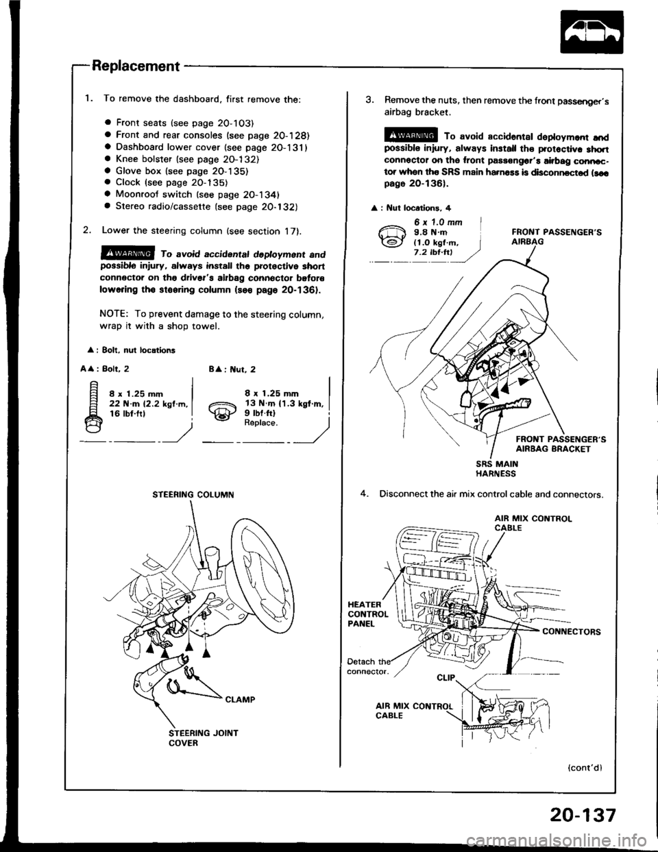
Replacement
To remove the dashboard, first remove the:
a Front seats (see page 2O-103)
a Front and rear consoles (see page 20-128)a Dashboard lower cover (see page 2O-131)a Knee bolster (see page 2O-132)a Glove box lsee page 2O-135). Clock (see page 20-135)
a Moonroot switch (see page 20-1341a Stereo radio/cassette {see page 20-132)
Lower the steering column (see section 17).
@@ ro avoid accidentat dedoyment andpossiblo in ury, always install the prot€ctive short
connector on tho drivsr's airbag connector bgtor€
lowering tho stooring column (so€ page 20-1361.
NOTE: To prevent damage to the steering column,
wrap it with a shoD towel.
: 8olt, nul locations
A
: Bolt, 28 : ut, 2
8 x 1.25 mm22 N-m 12.2 ksl.m,16 lbt.frl
8 x 1.25 mm
gill$"'l
STEERING COLUMN
3. Remove the nuts, then remove the front passsnger,s
airbag bracket,
@ To avoid accidantar daploym.nr ",'dpossibls iniury, always install th€ protoctiv. 3hqtconnoctor on tho ,ront passongor'a airbag conncc-tor whon tha SRS main ha.na$ is disconncctod llcrpago 20-136).
: Nut locatlons, 4
FRONT PASSENGER'S
FRONT PASSENGER'SAIRBAG BRACKET
4.
SRS MAINHARNESS
Disconnect the air mix controlcable and connectors.
AIR MIX CONTROLCAELE
CONNECTORS
(cont'dl
20-137
Page 1007 of 1413
Dashboard
Replacement (cont'd)
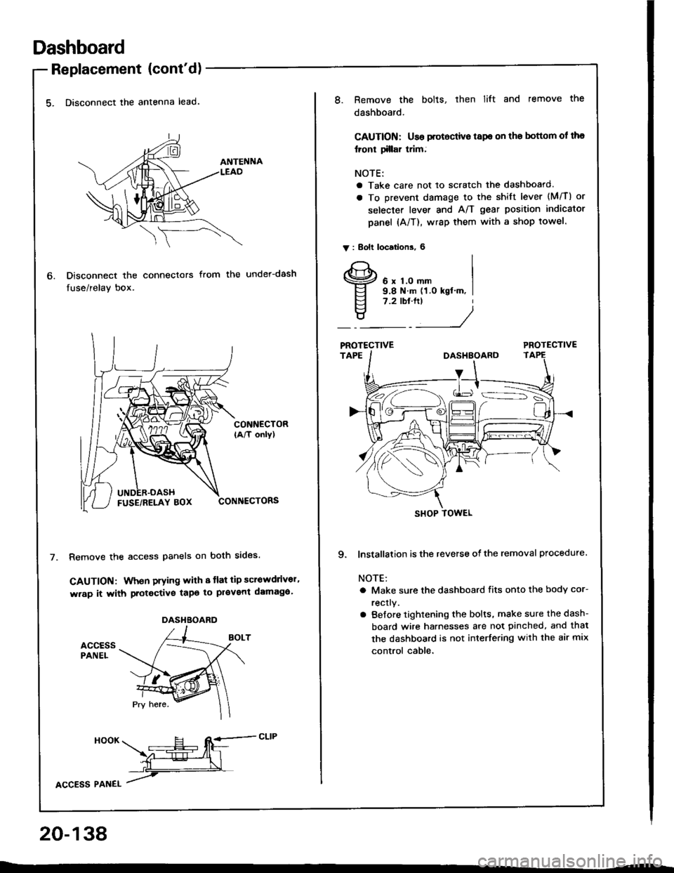
5. Disconnect the antenna lead.
Disconnect the connectors
fuse/relay box.
from the under-dash
CONNECTOR(A/T only)
CONNECTORS
Remove the access panels on both sides.
GAUTION: When prying with 8 tlat tip scrowdrivor'
wrap it with protective tapo to pl€vent damaga'
accEssPANEL
6.
DASHBOARD
HooK ___E-- RE=-cLrP
ffiL
lcCesS Plnel /
20-138
8.Remove the bolts, then lift and remove the
dashboard.
CAUTION: Use protoctive tspe on the bottom ol tha
lront tillar trim;
NOTE:
a Take care not to scratch the dashboard.
a To prevent damage to the shift lever (M/T) or
selecter lever and A/T gear position indicator
panel (A/T), wrap them with a shop towel.
V : Bolt locations, 6
6 x 1.0 mm9.8 N.m (1.0 kgt'm, I7.2 tbt.ftt
____/
PROTECTIVE
9. lnstallation is the reverse of the removal procedure
NOTE:
a Make sure the dashboard fits onto the body cor-
rectly.
a Before tightening the bolts, make sure the dash-
board wire harnesses are not pinched, and thal
the dashboard is not interfering with the air mix
control cable.
SHOP TOWEL
Page 1027 of 1413
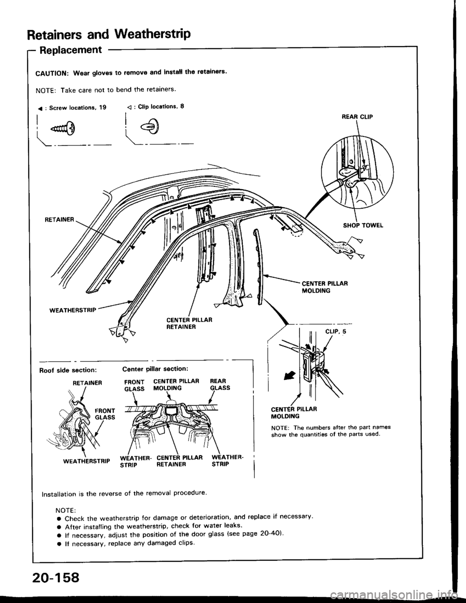
Retainers and WeatherstriP
Replacement
CAUTION: Wear gloves to lemov€ and install tho i€tain€rs'
NOTE: Take care not to bend the retarners.
< : Screw localions, 19 < : Clip locations, I
| .€\
!:
l{SHOP TOWELq
CENTER PILLARMOLDING
Boot side section:
I
RETAINER
lnstallation is the reverse of the removal procedure.
NOTE:
a Check the weatherstrip lor damage or deterioration, and replace if necessary'
a After installing the weatherstrip, check for water leaks'
a lf necessary, adjust the position of the door glass (see page 20-40)
a It necessarv, replace any damaged clips.
Center oillar section:
FRONT CENTER PILLAR
CENTER PILI-ARMOLDING
NOTE: The numbers atter the part names
show the quantities ot the parts used
!9
RETAINER
WEATHERSTRIP
REAR CLIP
RETAINER
WEATHERSTRIP
20-158
Page 1047 of 1413
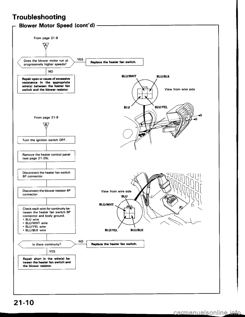
Does the blower motor run atprogressively higher speeds?Raplaca tho hollar fan rwitch.
Ropair opon or cau36 ol oxcoalivtrosbtanco in tho appaopaiatowire(3| b6twoon thg hostct lanswitch and tho blower todstor.
Turn the ignition switch OFF.
Remove the heater control panel(see page 21-25).
Check each wire for continuity be-tween the heater tan switch 6Pconnector and body ground.. BLU wire. BLUMHT wire. BLU/YEL wke. BLU/BLK wire
Raplaca tha haater lan awltch.
Bopair shon in the wir6{s} b€-lwo€n lho heatot lan switch rndth6 blowor ro3bto?.
From page 21-9
From page 21-9
View trom whe side
ilil
!\i
-l
I
View from wire side
BLU/U,HT
Troubleshooting
Blower Motor Speed (cont'd)
21-10
--
Page 1091 of 1413
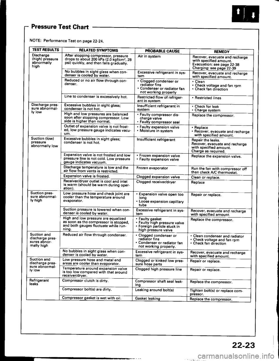
Pressure Test Chart
NOTE: Performance Test on page 22-24.
TEST RESULTSRELATED SYMPTOMSPROAABLE CAUSEREMEDYDischsrge(high) pressureabnormallynrgn
AftEr stopping compressor, pressuredrops to about 200 kPa (2.0 kof/cmr. 28psi) quickly, and then falls gr;dua y.
Air in systemRecover, evacuate and recharqowith sDecified amount. -
Evacuation: see Daqe 22-38Charoino: se6 D;op--2?-?qNo bubbles in sight g16ss when con-denser is cooled bv water.E-\cessive refrigerant in sys-Recover, evacuate and recharqewith specitied amount. -
Reduced or no air flow through con-oenser.Clogged condenser orradiato. finsCondenser o. radiator fannot working properly
CleanCheck voltage and fan rpmunecK lan ofeclton
Line to condenser is excessivelv hot.Restricted flow of refriger-ant In syslem. Restricted lines
Discharge pres-su re abnormal-Excossive bubbles in sight glass;condenser is not hot.Insuff icient refrigerant insyslemCheck for leakCharge systemHigh and low pressures are balancedsoon after stopping compressor. Lowside is higher than normal,
Faulty compressor dis-cnarge vaNsFaulty compressor seal
Replace the compressor.
Outlet of expansion vslve is not frost-ed, low pressure gauge indicates vacu-um,
. Faulty expansion valve. Moisture in sysiem. Replace. Recover, evacuate and recharoewith specified amount. -
Suction (lowlpressureabnormally low
Excessive bubbles in sight glass;conqenser rs not hot_Insuff icient ref rigerantReoair the leaks.Reaover, evacuate and recharoewith sDecifisd amount. -
Charqe as required.Expansion valve is not trosted and lowpressur€ line is not cold. Low pressuregauge Inorcates vacuum.
Frozen expansion valveFaulty expansion valveReplace the expansion valve.
Discharge temperaturg is low and theair flow from vents is restricted.Froren evaporatorRun the tan with comoressor oftthen check Ay'C thermostat.Expansion valve is frost€d.Clogged expansion valveCl€an or replace.Receiver/dryer outlet is cool and inletisrryarm (should be warm during oper-Clogged r€ceiver/dry€rReplace
Suction pres-su re abnormal-ly high
Low pressure hose and check joint arecooler than the temDeraturo aroundevaDorator.
'
ffin"nsion u"lu" oD"n too
. Loose expansion capillary
Repair or replace.
Suction pressure is lowered when con-denser is cooled by water,Excessive refrigerant in sys-remRecover, evacuate and recharqewith sDecifi€d amount. -
High and low pressure are equalizedas soon as the compressor is stopped,and both gauges fluctuate while run-nrng.
Faultv oasketFaulty Figh pressure valveForeign particle stuck inhigh pressure valve
Replace the compressor.
Suction anddischarg€ pres-sufes aonor-mally high
Reduced air flow through condenser.. Clogged condenser orradiator fins. Condenser or radiator fannot working properly.
Clean condenser and radiatorCheck voltage and fan rpmCheck fan direcrion
No bubbles in sight glass when con-cl€nser is cooled bv water.Excessive refrigerant in sys-remRgcover, €vacuate and recharoewith sp€cified amount.Suction snddischarge pres-su r€ abnormal-
Low pressure hose and metal endafeas are cooler than evaDorator.Clogged or kinked tow pre€-sure nos€ pansFepair or replace.
Temperature around expansion valveis too low compared with that aroundrecerver/orver.
Clogged high pressure lineRepair or replace.
Refrig€rantleaksCompressor clutch is dirty.Compressor shaft seal leak-IngReplace the comDressor.
Compressor bolt(s) are dirty.Leaking around bolt(s)Tighten bolt(sl or replace com-pressor.Compressor gasket is wet with oil. IGasket leakingReplace the compressor.
22-23
Page 1104 of 1413
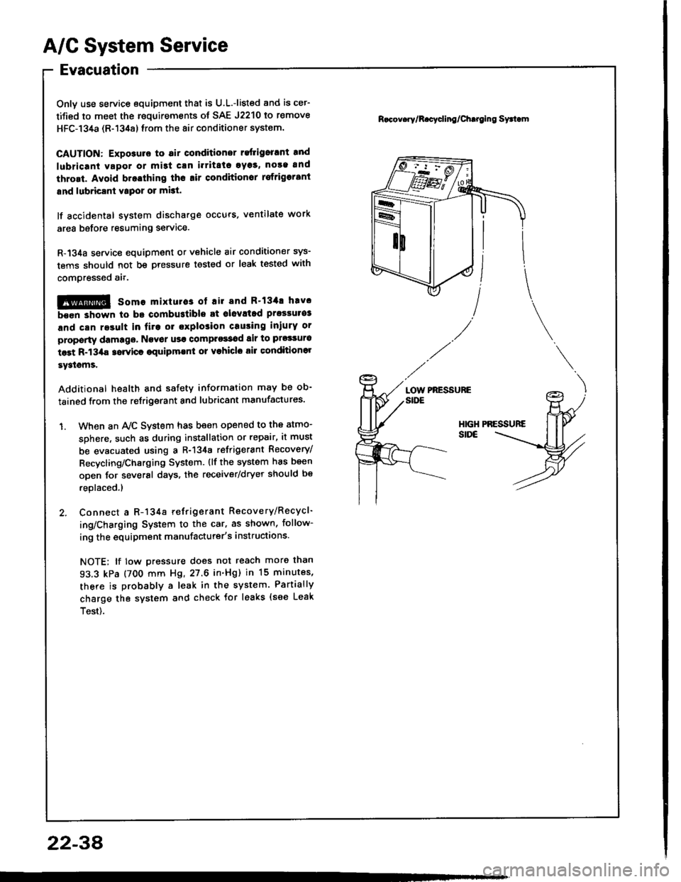
A/G System Service
Evacuation
Only use service equipment that is U.L.-listed and is cer-
tified to meet the roquirements of SAE J2210 to remove
HFC-134a (R-134a) lrom the 8ir conditioner system.
CAUTION: Exposulo to 6ir conditioner refligorrnt and
lubricani vapor or mi3t crn i.ritato 9y33, noaa and
thrort. Avoid bratthing ths .ir conditionor rsfrigorrnt
snd lubricsnt vtpor or mist.
lf accidental system discharge occurs, ventilate work
area before resuming service.
R-134a service equipment or vehicle 8ir conditioner sys-
tems should not be pressure tested or leak tested with
compressed ait.
!@ somo mixtuto3 ot ril and R'134! hav.
been shown to bo combustible at olevltad prossulo3
and can re3ult in fire or explosion crusing inlurY or
property damago, Navor us! comprossod air to prgsauro
test R-13/aa 3orvicr €quipmlnl or vohiclo air conditionol
sy3lems.
Additional health and safety information may be ob-
tained from the retrigerant and lubricant manufactures.
1. When an Ay'C System has been opened to the atmo-
sDhere, such as during installation or repair, it must
be evacuated using a R-134a refrigerant Recovery/
Recycling/Charging System. {lf the system has been
open for several days, the receiver/dryer should be
replaced.l
2. Connect a R-134a refrigerant Recovery/Recycl-
ing/Charging System to the car, as shown, follow-
ing the equipment manufacturer's instructions.
NOTE; lf tow pressure does not reach more than
93.3 kPa (700 mm Hg, 27.6 in'Hg) in 15 minutes,
there is probably a leak in the system. Partially
charge the system and check tor leaks {see Leak
Test).
R.cov.ry/R.cycling/Chtroing Syttom
PRESSUREaotnSIDE
2234
Page 1120 of 1413
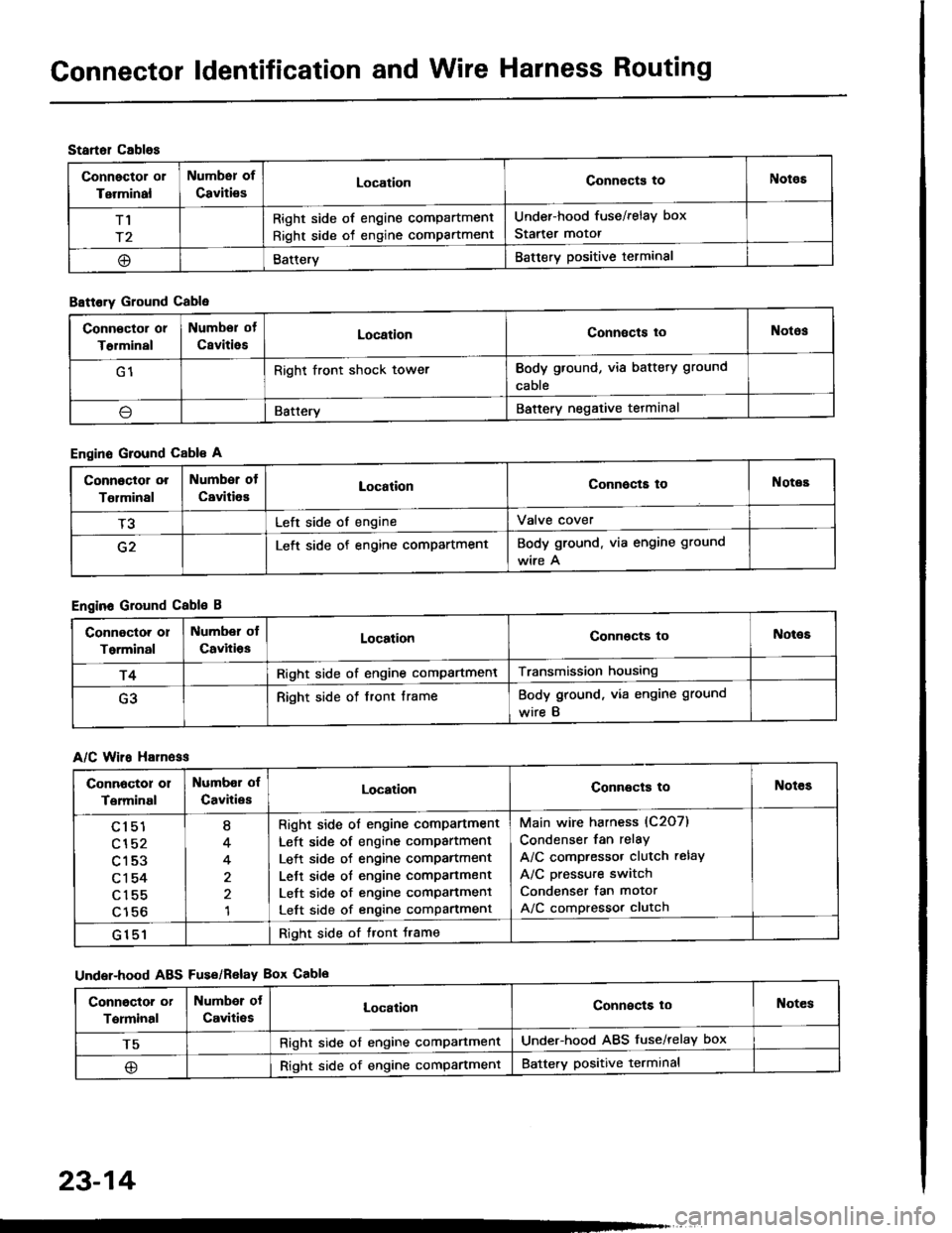
Gonnector ldentification and Wire Harness Routing
Startol cablos
Connector or
Terminal
Numbsr of
CavitiesLocationConnects toNotos
T1
r2
Right side of engine compartment
Right side of engine compartment
Under-hood fuse/relay box
Starter motor
@BatteryBattery positive terminal
B8ttory Ground Cable
Engine Ground Cable A
Engine Ground Cable B
A/C Wiro H81n6ss
Under-hood ABS Fus€/Relav Box Cablo
Conn€ctor or
T€rminal
Numbor of
CsvitiesLocationConnects toNotos
G1Right front shock towerBody ground, via battery ground
cable
\lBatteryBattery negative tetminal
Connoctor or
Tolminal
Number of
CavitiesLocationConnocta toNotes
T3Left side of engineValve cover
G2Left side of engine compartmentBody ground. via engine ground
wire A
Connoctor or
Torminal
Number ol
CavitiosLocationConnocts toNot€s
r4Right side of engine compartmentTransmission housing
G3Right side of front frameBody ground, via engine ground
wire B
Connoctor 01
Terminal
Numbor of
CavitiesLocationConnects toNotes
cl51
cl52
c153
c1 54
c155
c156
I
4
4
1
Right side ol engine comPartment
Left side of engine compartment
Left side of engine comPartment
Lett side ot engine compartment
Left side of engine comPanment
Left side of engine compartment
Main wire harness (C2O7)
Condenser fan relay
A/C compressor clutch relay
A/C pressure switch
Condenser fan motor
A/C compressor clutch
G151Right side of tront Jrame
Conngctor or
Terminal
Numbor ot
Caviti€sLocalionConnects loNotes
T5Right side of engine comPartmentUnder-hood ABS fuse/relay box
@Right side of engine compartmentBattery positive terminal
23-14
Page 1161 of 1413
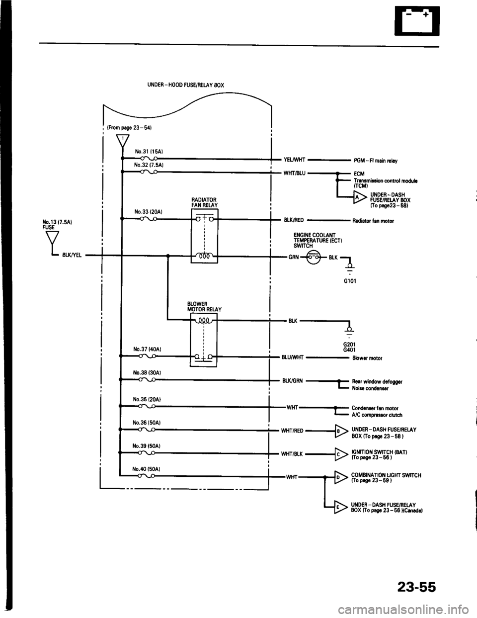
{From p.So 23 - 541
No.l317.5AlFUSE
VL swyel
UNDER _HOOD FUSE/NEUY 8OX
n^OIATORFAN REI-AY
BTOWERMOTOR RETAY
YELJWHT - PGM -R mlin |rhv
TrdEmirConco rolrl|oduLfrcMt
UI{DEF -OASHFUSSRELAY BOXtTo p!9c23 - 581
8LK/RED - Radi.tor fln molor
ENGII{E COOTAMITEMPEMTURE IECT)swtTcH
*@"r;1
o iot
'"----
G20tG40t8LU/WHT - 8bw.r motor
8tX/GRtl -f R!!r window d,.to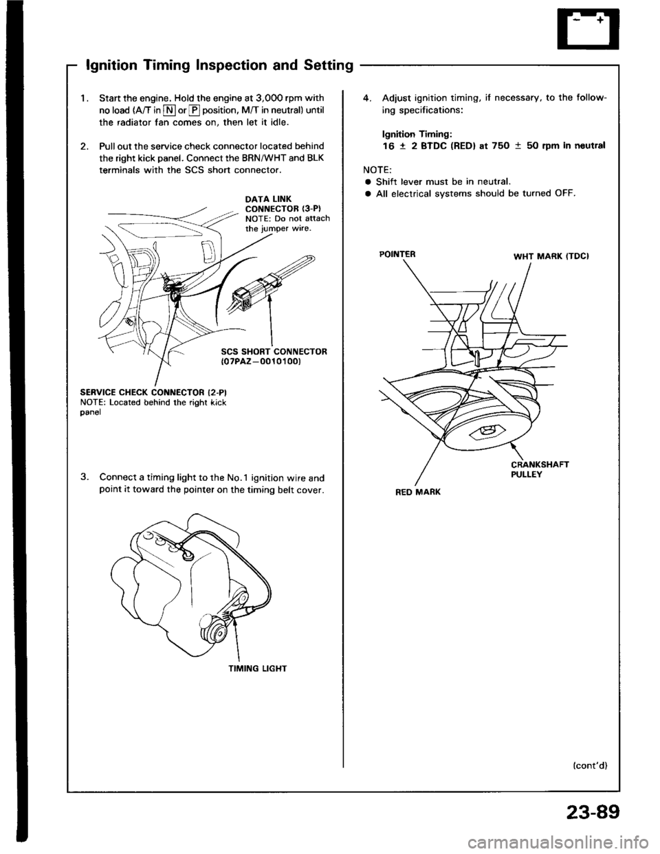
lgnition Timing Inspection and Setting
1.Start the engine. Hold the engine at 3,00O rpm with
no load (A/T in S or E position, M/T in neutral) until
the radiator fan comes on, then let it idle.
Pull out the service check connector located behind
the right kick panel. Connect the BRN/WHT and BLK
terminals with the SCS short connector.
4. Adiust ignition timing, if necessary, to the follow-
ing specifications:
lgnition Timing:
16 t 2 BTDC (RED) at 75O 1 50 rpm in noutral
NOTE:
a Shift lever must be in neutral.
a All electrical systems should be turned OFF.DATA LINKCONNECTOR {3-P}NOTE: Do not attachthe jumper wire.
POINTER
SCS SHORT CONNECTOR{0?PAZ-O010't 00t
SERVICE CHECK CONNECTOR I2.PINOTE: Located behind the right kickoanel
Connect a timing light to the No.1 ignition wire andpoint it toward the pointer on the timing belt cover.
TIMING LIGHT
lcont'd)
REO MARK
23-89