HONDA INTEGRA 1994 4.G Workshop Manual
Manufacturer: HONDA, Model Year: 1994, Model line: INTEGRA, Model: HONDA INTEGRA 1994 4.GPages: 1413, PDF Size: 37.94 MB
Page 541 of 1413
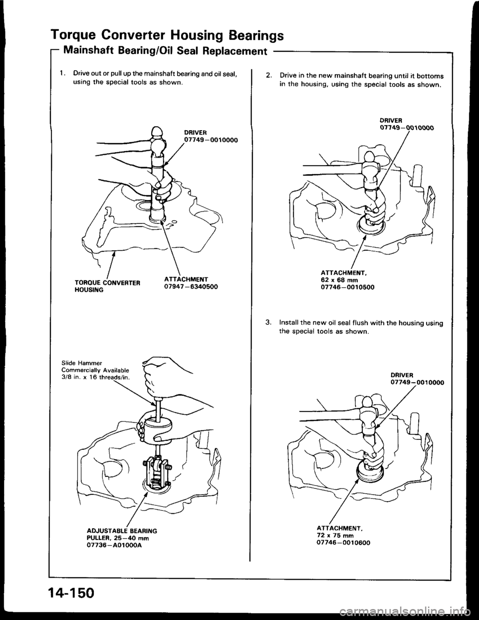
Torque Converter Housing Bearings
Mainshaft Beadng/Oil Seal Replacement
1 . Drive out or pull up the mainshaft bearing and oil seal,using the special tools as shown.
Slide HammerCommercially Available3/8 in. x 16
07749 -OOIOOOO
14-150
2.Drive in the new mainshaft bearing until it bottomsin the housing, using the special tools as shown.
3.Installthe new oil seal flush with the housing usingthe sDecial tools as shown.
ATTACHMENT,62x68mm07746-0010500
ATTACHMENT,72x75mm07746-0010600
DRIVEN
Page 542 of 1413
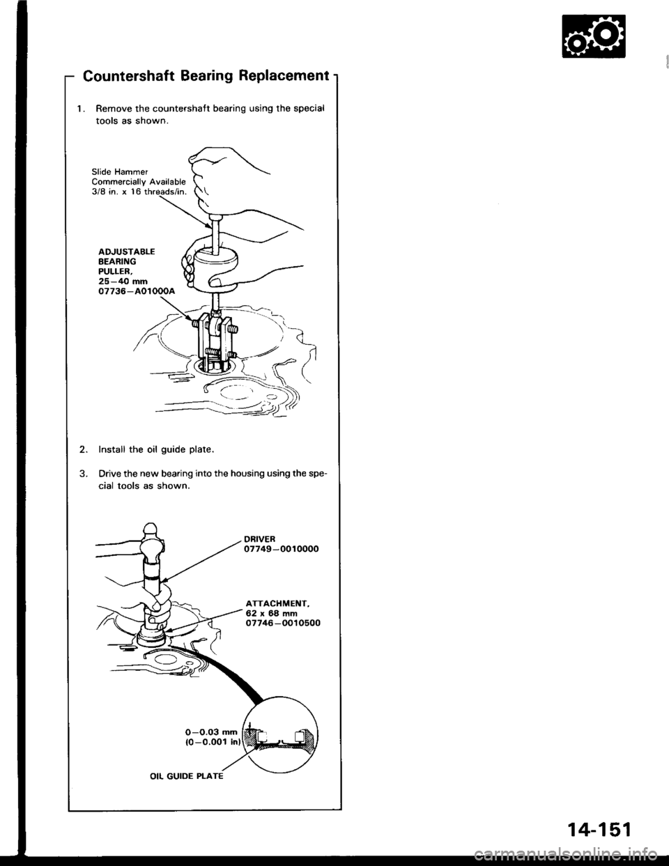
Countershaft Bearing Replacement
l. Remove the countershatt bearing using the special
tools as shown.
Slide HammerCommercially Available3/8 in. x 16
ADJUSTABLEBEARINGPULLER,25-40 mm07736-AOIOOOA
K
'/'
-)-i.
-:-:-:1.-=41"
Install the oil guide plate.
Drive the new bearing into the housing using the spe-
cial tools as shown.
14-151
Page 543 of 1413
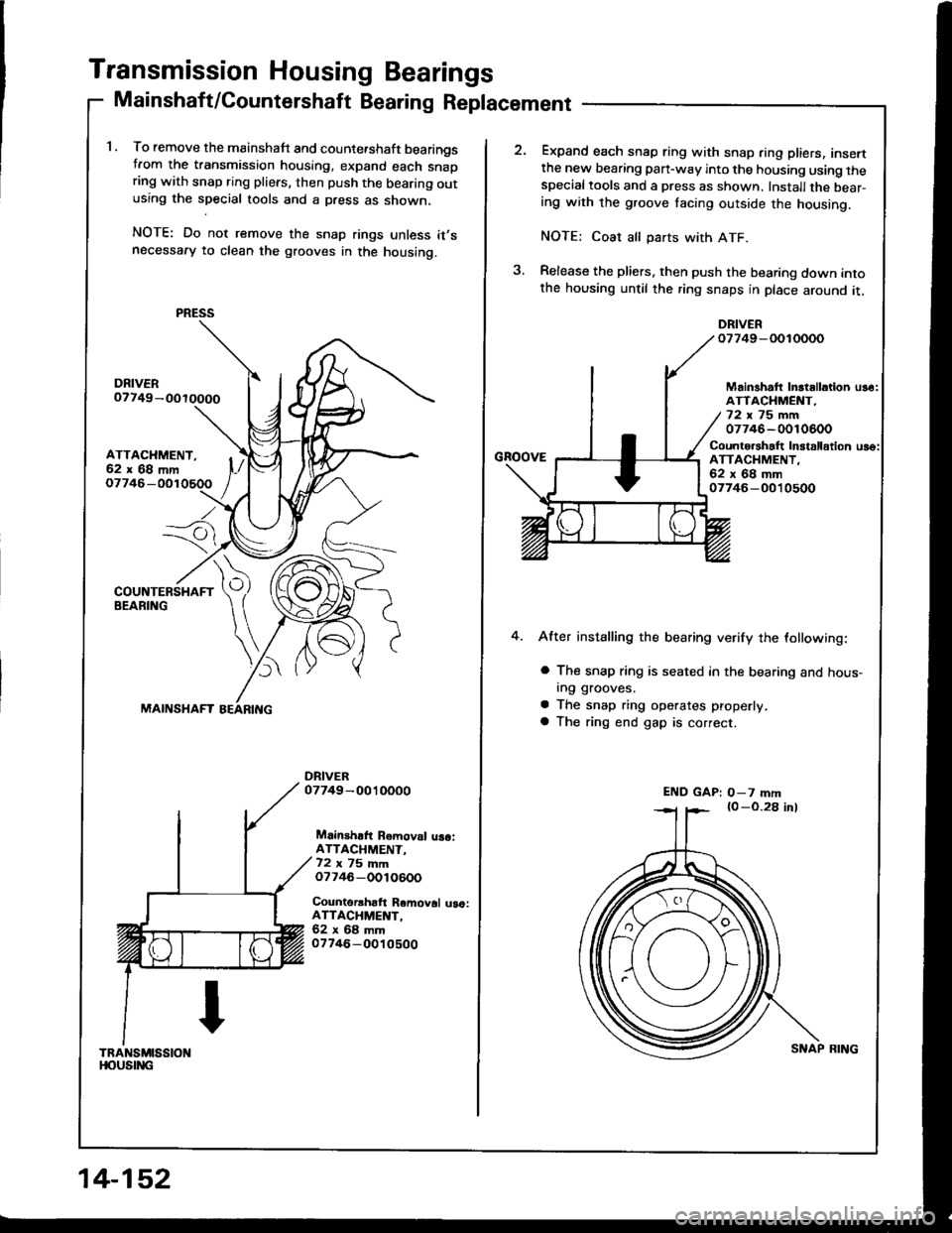
Transmission Housing Bearings
Mainshaft/Countershaft Bearing Replacement
1. To remove the mainshaft and counte.shaft bearingstrom the transmission housing, expand each snapring with snap ring pliers, then push the bearing outusing the special tools and a press as shown,
NOTE: Do not remove the snap rings unless it,snecessafy to clean the grooves in the housing.
ATTACHMENT,62x68mm
Io7746-
---7i
)
MAINSHAFT
Mainshaft Removal uaoiATTACHMENT-72 ,, 75 mmo7746-OOlO600
Counterrhaft Removal uao:ATTACHMENT,62x68mm07746-O010500
TRANSMISSIONt|oustitc
PRESS
14-152
SNAP BING
Expand each snap ring with snap ring pliers, insertthe new bearing pan-way into the housing using thespecialtools and a press as shown. Installthe bear-ing with the groove tacing outside the housing.
NOTE: Coat all parts with ATF.
Release the pliers. then push the bearing down intothe housing until the ring snaps in place around it,
DRIVERo7749-OOIOOOO
GnoovE
Mainshatt Inltallation us6:ATTACHMENT,72x75mm07746-0010600
Counto.shalt In3talldtion uso:ATTACHMENT.62x68mm07746-O010500
4.After installing the bearing verify the lollowing:
a The snap ring is seated in the bearing and hous-In9 grooves.
a The snap ring operates properly
a The ring end gap is correct.
END GAP: O-7 mm
Page 544 of 1413
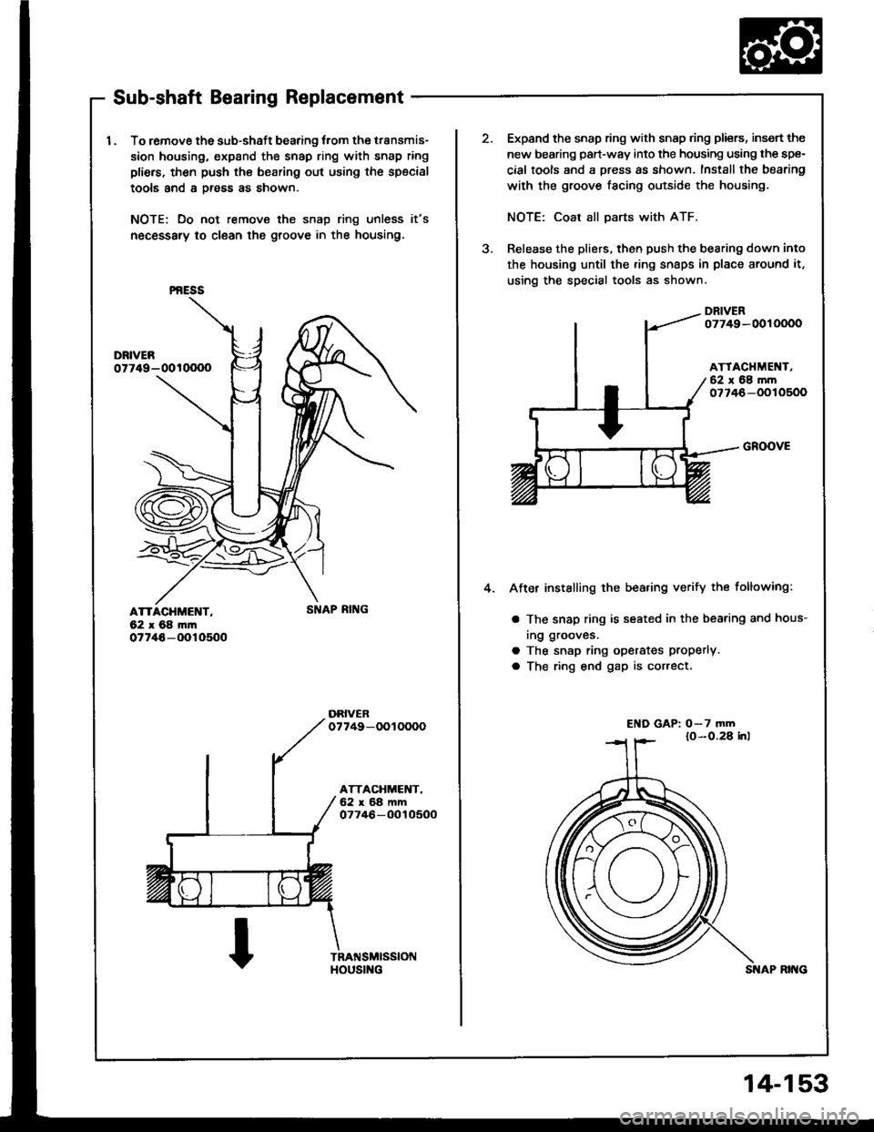
Sub-shaft Bearing Replacement
I . To remove the sub-shaft bearing lrom the transmis-
sion housing, expand the snap ring with snap ring
pliers, then push th€ bearing out using the special
tools and a Dress as shown.
NOTE: Do not remove the snap ring unless it's
necessary to clean the groove in the housing.
ATTACHMENT,62x68m|n07746-(Xr10500
PNESS
HOUS[{G
2.Expand the snap ring with snap ring pliers, insert the
new bearing part-way into the housing using the spe-
cial tools and a press as shown. Install the bearing
with the groove facing outside the housing.
NOTE: Coat all parts with ATF.
Release the pliers, then push the bearing down into
the housing until the ring snaps in place around it,
using the special tools as shown.
DRIVER07749-0010000
ATTACHMEI{T,62 x 68 mrn077/+6-OOlO500
a
4.
GROOVE
After installing the bea.ing verify the following:
a The snap ring is seated in the bearing and hous-
ing grooves.
a The snap ring operates Properlva The ring end gap is correct.
El{D GAP: o-7 mm
14-153
Page 545 of 1413
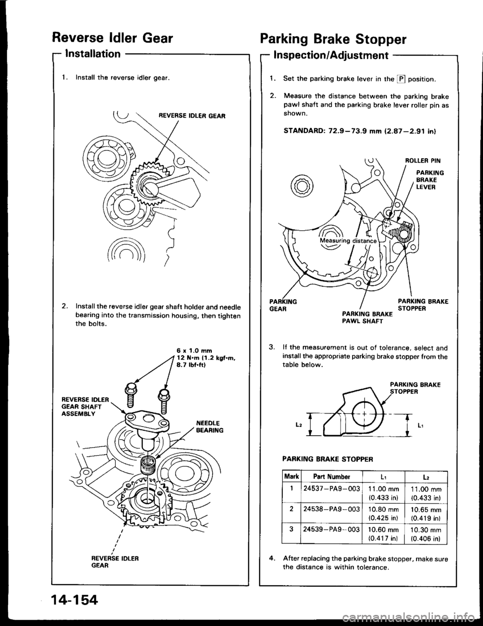
Reverse ldler Gear
Installation
Parking Brake Stopper
Inspection/Adjustment
1.
2.
Set the parking brake lever in the E position.
Measure the distance between the parking brakepawl shaft and the parking brake lever roller pin as
shown.
STANDARD: 72.9-73-g mm (2.87-2.91 in)
ROLLER PIN
PANKINGBRAKELEVER
PARKING BRAKESTOPPERPARKING BBAKEPAWL SHAFT
lf the measurement is out of tolerance, select andinstall the appropriate parking brake stopper from thetable below.
PARKING BRAKE STOPPER
After replacing the parking brake stopper, make su.e
the distance is within tolerance.
4.
7A\Meaauring\v
MarkPart NumbolLz
124537 - PA9- 0031 1.00 mm
{0.433 in}
11.00 mm
{0.433 in)
224538-PA9 -00310.80 mm(0.425 in)
10,65 mm(0.419 inl
24539- P49,00310.60 mm(0.417 in)
10.30 mm
{0.406 in)
1. Install the reverse idler gear.
Installthe reverse idle, gear shaft holder and needlebearing into the transmission housing, then tightenthe bolts.
6 x l.O mm12 N'm 11.2 kgt.m.4.7 lbf.ft)
14-154
Page 546 of 1413
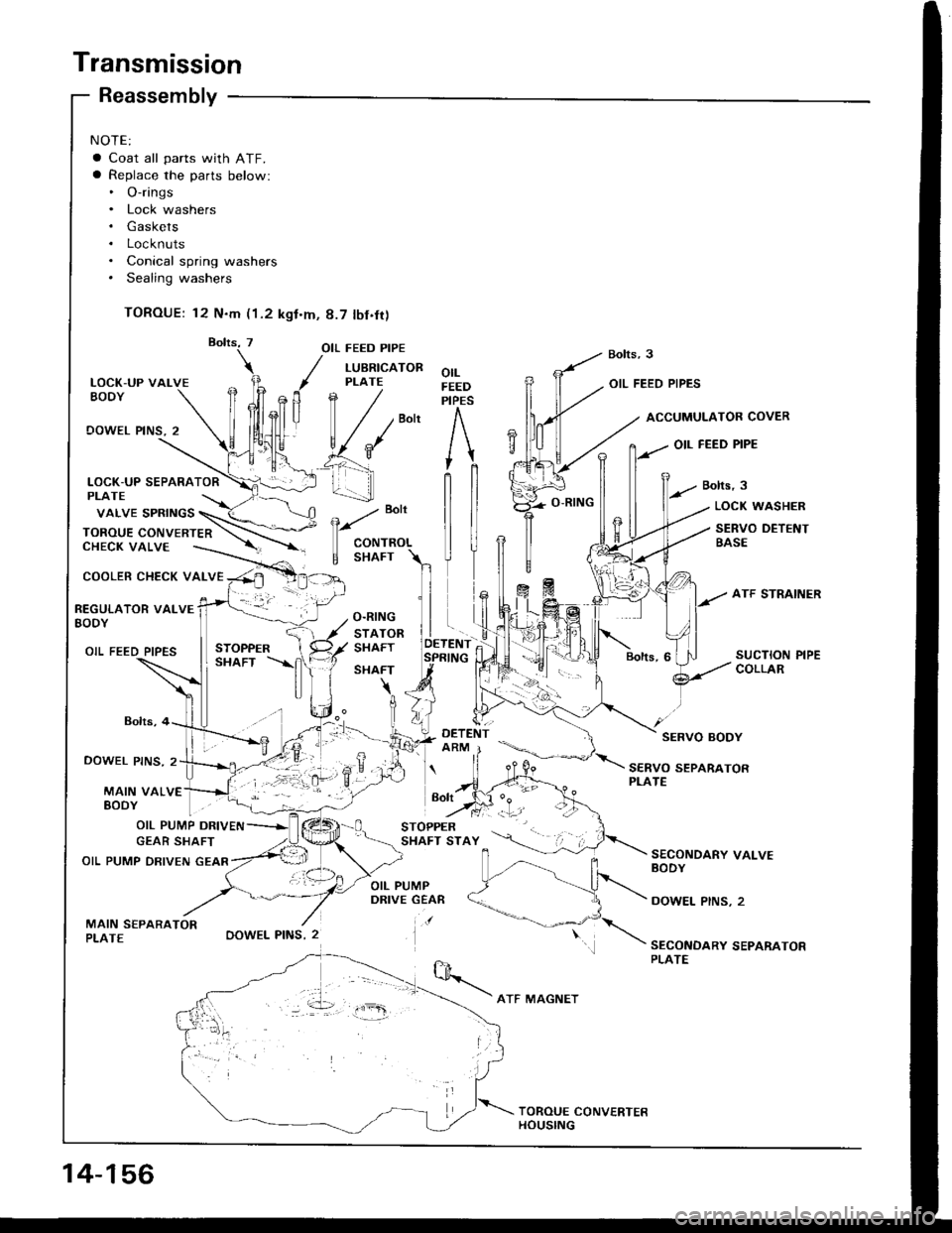
Transmission
NOTE:
a Coat all parts with ATF.a Replace the parts below:. O-rings. Lock washers. Gaskets. Locknuts. Conical spring washers. Sealing washers
TOROUE: 12 N.m (1.2 kgt.m, 8.7 tbf.fr)
LOCK-UP VALVEEODY
OOWEL PINS, 2
COOLER CHECK VALVE
Reassembly
Bolts,4
DOWEL PINS. 2
MAIN VALVE
OIL FEED PIPE
/ LUBRTcAToR
, PLATE
fln /
| / /""n
v{*' e'f _\
_! 1.-...-]]
-. :-,.
OOWEL PINS, 2
orLFEEDPIPES
OIL FEED PIPES
ACCUMULATOB COVER
OIL FEED PIPE
Bolts,3
e
"o't
CONTROL
E SHAFT
LOCK WASHER
SERVO DETENTBASE
REGULATOR VALVEBODY
OIL FEED PIPES
SERVO BODY
SERVO SEPARATORPLATE
EoDY | . "1-
OIL PUMP DRIVEN
GEAR SHAFT
OIL PUMP DRIVEN GEAR
MAIN S€PARATORPLATE
SECONDARY VALVEBODY
DOWEL PINS, 2
SECONDARY SEPARATORPLATE
vaLVE spRtNGS \_(< \
ToRou E coN vE RTE n \-\.--CHECK VALVE ----.-. --'r -
Bolt
14-156
ATF MAGNET
Page 547 of 1413
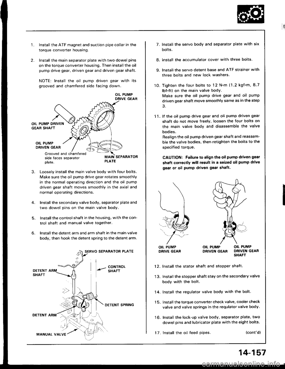
2.
1.Install the ATF magnet and suction pipe collar in the
torque converter nousrng.
Install the main separator plate with two dowel pins
on the torque converter housing. Then install the oil
pump drive gear, driven gear and driven gear shalt.
NOTE| Install the oil pump driven gear with its
grooved and chamtered side facing down.
OIL PUMPDRIVE GEAR
OIL PUMPORIVEN GEAR
Grooved and chamferedside faces separatorplate.
J.Loosely install the main valve body with Iour bolts.
Make sure the oil pump drive gear rotates smoothly
in the normal operating direction and the oil pump
driven gear shaft moves smoothly in the axial and
normal operating directaons.
Install the secondary valve body, separator plate and
two dowel pins on the main valve body.
Installthe control shaft in the housing, with the con-
trol shatt and manual valve togelher.
Install the detent arm and arm shatt in the main valve
body, then hook the detent spring to the detent arm.
SERVO SEPARATOR PLATE
--- 8ixli"'
6.
36
DETENTSHAFT
DETENT ARM
MANUAL VALVE
DETENI SPRING
17. Install the oil feed pipes.
14-157
E'.:
7. Install the servo body and separator plate with six
bolts.
8. lnstall the accumulator cover with three bolts
9. lnstall the servo detent base and ATF strainer with
three bolts and new lock washers.
10. Tighten the four bolts to 12 N.m (1.2 kgf'm, 8.7
lbf.ft) on the main valve body.
Make sure the oil pump drive gear and oil pump
driven gear shaft move smoothly same as in the step
11. lf the oil pump drive gear and oil pump driven gear
shaft do not move freelY. loosen the four bolts on
the main valve body and disassemble the valve
bodies.
Realign the oil pump driven gear shaft and reassem-
ble the valve bodies, then retighten the bolts to the
specified torque,
CAUTION: Failure to align the oil pump d1iv6n gear
shaft corroctly will result in a seized oil pump drivo
geal of oil pump drivon gear shatt.
l\
(...l
=..�N
L,1ffi#
j-*/:
OIL PUMPDRIVE GEABOIL PUMP OIL PUMPDRIVEN GEAR DRIVEN GEARSHAFT
12. Install the stator shaft and stopper shatt.
13. Install the stopper shatt stay on the secondary valve
body with the bolt.
14. Install the regulator valve body with the bolt.
1 5. Install the torque converter check valve, cooler check
valve and valve springs in the requlator valve body.
16. Install the lock-up valve body, separator plate, two
dowel pins and lubricator plate with the eight bolts.
(cont'dl
Page 548 of 1413
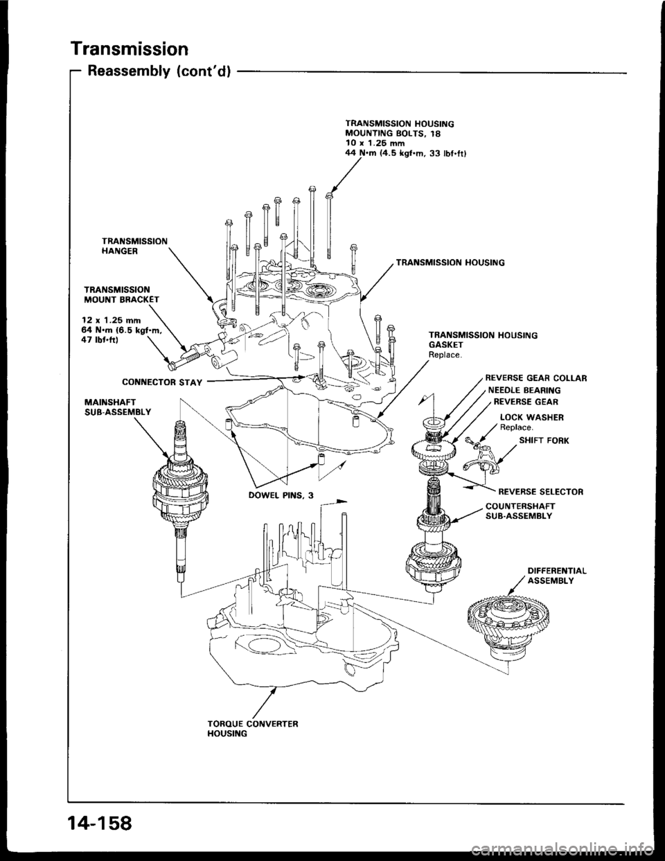
Transmission
12 x '1.25 fifi64 N.m {6.5 kgt'm,47 tbt'tr)
CONNECTOR STAY
Reassembly (cont'dl
TRANSMISSIONHANGER
TRANSMISSIONMOUNT BBACKET
MAINSHAFTSUB-ASSEMBLY
TRANSMISSION HOUSINGMOUNTING BOLTS, 18l0 x 1.25 mm
fl
44 N.m (4.5 kgl.m. 33 lbf.trl
TRANSMISSION HOUSING
T=
TRANSMISSION HOUSINGGASKETReplace.
REVERSE GEAR COLLAR
NEEOLE BEARING
REVEBSE GEAR
LOCK WASHERReplace.
SHIFT FORK
REVERSE SELECTORDOWEL PINS, 3
COUNTERSHAFTSUB.ASSEMBLY
DIFFERENTIALASSEMBLY
TOROUE CONVERTERHOUSING
14-158
Page 549 of 1413
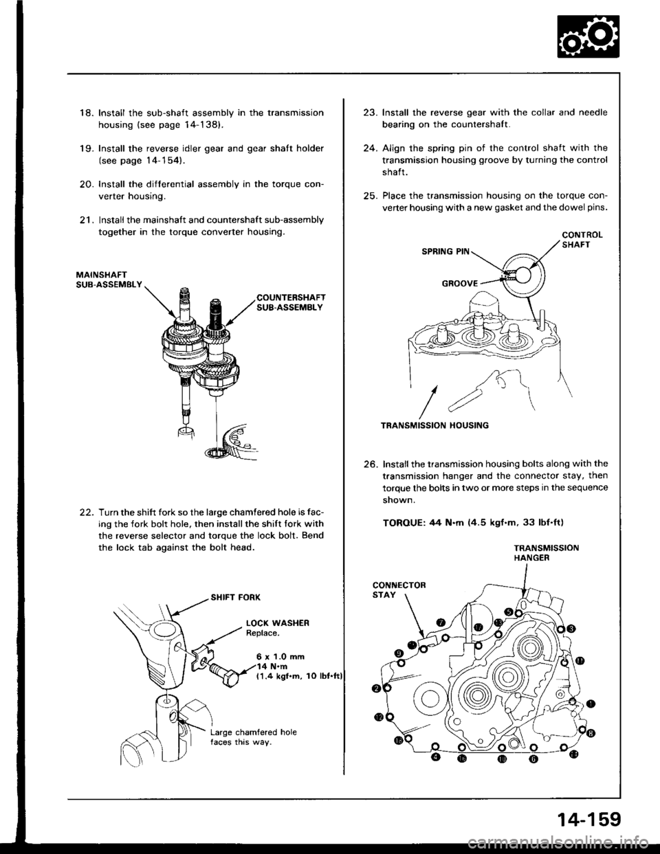
18. Install the sub-shaft assembly in the transmission
housing {see page 14-138).
19- Install the reverse idler gear and gear shatt holder
(see page 14-154).
20. Install the differential assembly in the torque con-
verter housing.
21. Install the mainshaft and countershaft sub-assembly
together in the torque converter housing.
MAINSHAFTSUB.ASSEMBLY
COUNTERSHAFTSUB.ASSEMBLY
22.Turn the shift fork so the large chamtered hole is fac-
ing the fork bolr hole. then installthe shift fork with
the reverse selector and torque the lock bolt. Bend
the lock tab against the bolt head.
SHIFT FORK
LOCI( WASHERReplace.
6 x 1.0 mm4 N.m(1.4 kgl.m, rO lbt.ft)
Large chamfered holefaces this way.
,,1
24.
lnstall the reverse gear with the collar and needle
bearing on the countershalt.
Align the spring pin of the control shaft with the
transmission housing groove by turning the control
shalt.
Place the transmission housing on the torque con-
verter housing with a new gasket and the dowel pins.
CONTROL
/K"\
//2"\TRANSMISSION HOUSING
Install the transmission housing bolts along with the
t.ansmission hanger and the connector stay, then
torque the bolts in two or more steps in the sequence
shown.
TOROUE: 44 N.m (4.5 kgf.m, 33 lbf'ft)
TRANSMISSIONHANGER
25.
CONNECTOR
14-159
Page 550 of 1413
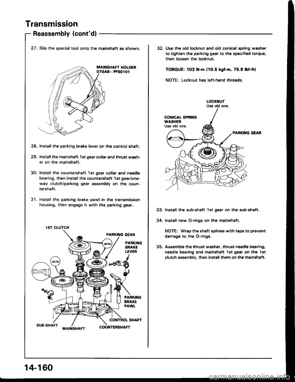
Transmission
Reassembly (cont'dl
SUB-SHAFT
27. Slip the special tool onto the mainshaft as shown.
MAII{SHAFT HOLDERoTGAa - PF5010I
Install the parking b.ake lever on the control shaft.
Installthe mainshaft 1st g6ar collar and thrust wash-
er on the mainshaft.
Install the countershaft 1st gear collar and n6€dls
bearing, then install the count€rshatt 1st gear/one-
way clutch/parking gea, assembly on the coun-
tershalt.
Install the parking b.ake pawl in th€ transmission
housing, then engage it with the parking gear.
PARKI''IG GEAR
PARTI GARAKELEVER
24.
29.
30.
31.
lST CLUTCH
14-1 60
MAIt{SHAFTCOU TERSHAFT
32. Use th6 old locknut and old conicsl spring washot
to tighten th€ parking gear to th€ sp€cifi€d torque,
then loosen the locknut.
TOROUE: 103 .m (1O.5 kgf.m, 75.9 lbf'ftl
NOTE: Locknut has left-hand threads.
PARKII{G GEAR
Install the sub-shaft lst gear on thg sub-shaft.
Install new O-rings on the mainshaft.
NOTE: Wrap the shaft splines with tspa to prevont
damago to the O-rings.
Assemblo th€ thrust wash6r, thrust naedle bearing,
needle bearing and msinshsft lst gear on tho lst
clutch assombly, then install them on the mainshaft.
33.
34.