HONDA INTEGRA 1994 4.G Workshop Manual
INTEGRA 1994 4.G
HONDA
HONDA
https://www.carmanualsonline.info/img/13/6067/w960_6067-0.png
HONDA INTEGRA 1994 4.G Workshop Manual
Trending: C917, knock sensor, coolant capacity, Park position switch, fuse box location, connector, warning
Page 571 of 1413
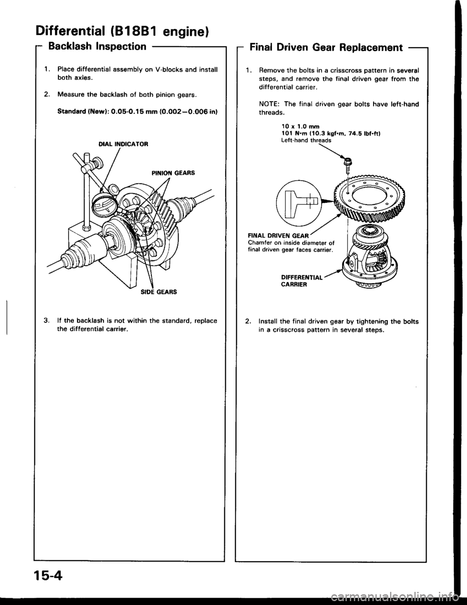
'1.Place difterential assembly on V-blocks and install
both axles.
M€asure the backlash of both pinion gears.
Standard (New):0.05-O.15 mm (0.OO2-0.006 inl
3. It the bscklssh is not within the standard, reDlace
the differential carrier.
DIAL II{OICATOR
Differential (818B1 enginel
Backlash InspectionFinal Driven Gear Replacement
1.Remove the bolts in a crisscross Datt€rn in several
steps, and remove the final driven gear from the
differential carrier.
NOTE: The final driven gear bolts have left-hand
threads.
10 x 1.0 mm101 N.m llO.3 kgl.m, 74.5 lbf.ftlLelt-hand threads
FINAL DRIVEIII GEARChamfer on inside diameter otlinal driven gear taces carrier.
DIFFEREI{TIALCARBIER
Install the final driven gear by tightening the bolts
in a c.isscross pattern in several steps.
15-4
Page 572 of 1413
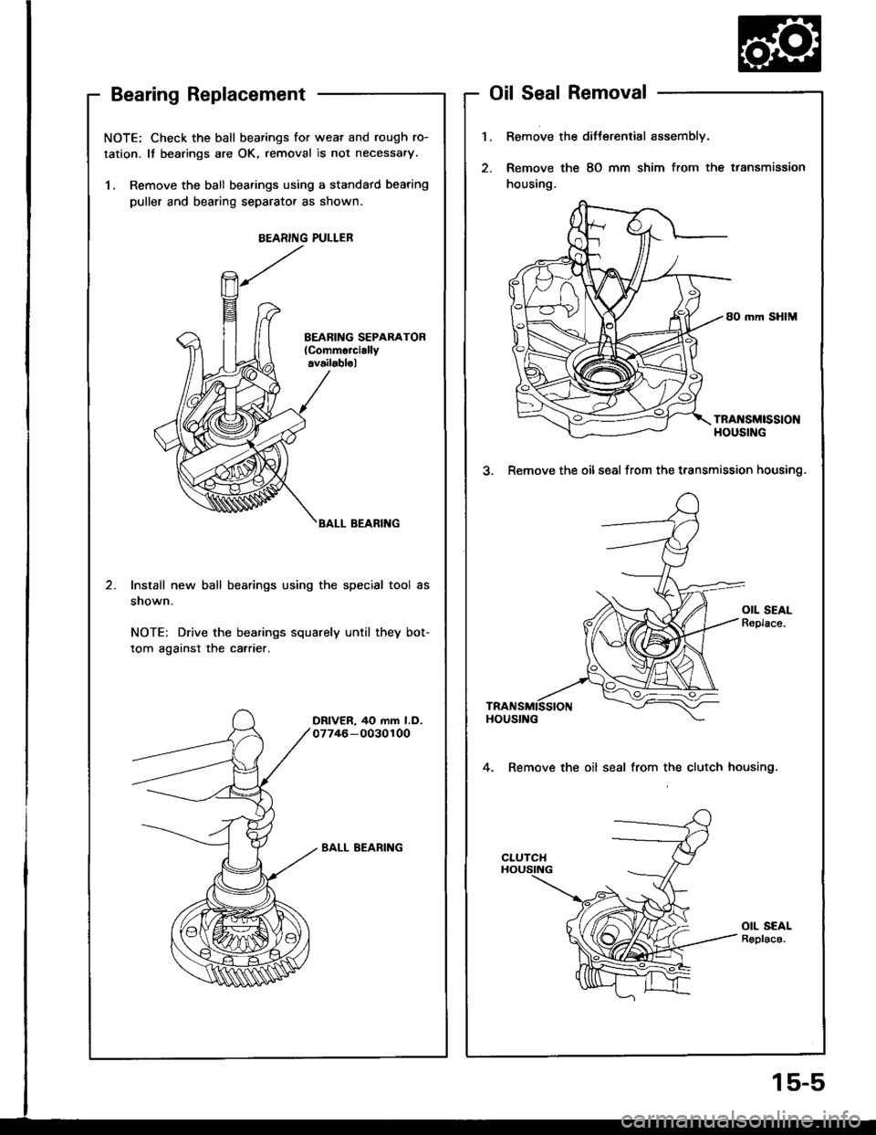
NOTE: Check the ball bearings for wear and rough ro-
tation. It bearings are OK, removal is not necessary.
1. Remove the ball bearings using a standatd bearing
puller and bearing separator as shown.
BEARING PULLEB
BALL BEARING
Install new ball bearings using the special tool as
snown.
NOTE: Drive the bearings squarely until they bot-
tom against the carrier.
DRIVER, 40 mm l.D.07746-0030100
BALL BEARING
Bearing ReplacementOil Seal Removal
1.Remove the ditterential assembly.
Remove the 8O mm shim from the transmission
housing.
80 mm SHIM
TRA[{SMtSStONHOUSING
3. Remove the oilseal from the t.ansmission housing.
4. Remove the oil seal from the clutch housing,
OIL SEALR€plac6.
15-5
Page 573 of 1413
Differential (81 881 engine)
Side Clearance Adjustment
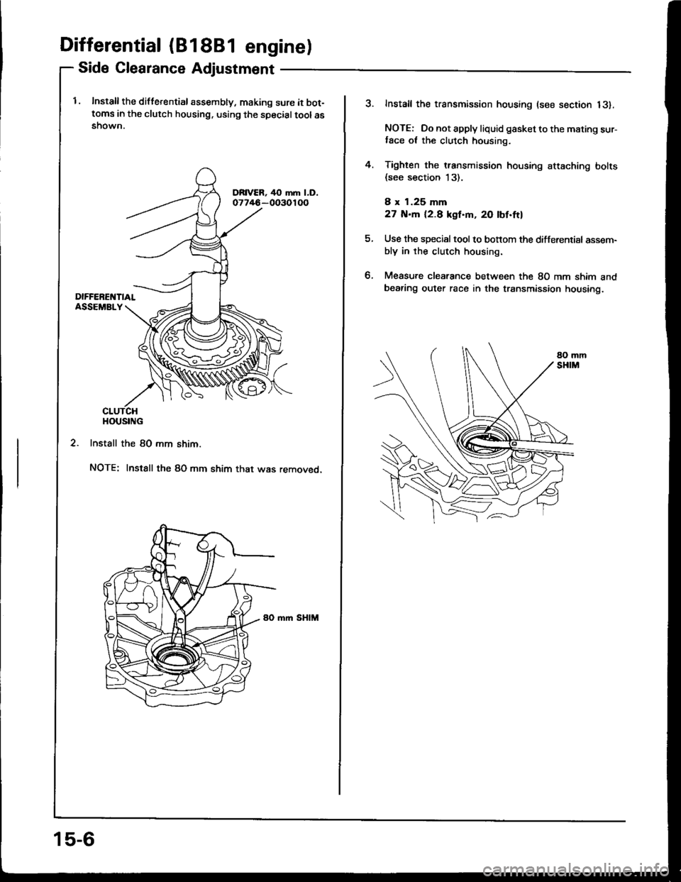
l. Install the diflerential assembly, making sure it bot-toms in the clutch housing. using the specialtoolasshown.
2. Install the 80 mm shim.
NOTE: Instsll the 80 mm shim that was removed.
mm SHIM
HOUSING
15-6
?Install the transmission housing (see section 13).
NOTE: Do not apply liquid gasket to the mating sur-,ace ot the clutch housing.
Tighten the transmission housing attaching bolts(see section 13).
8 x 1.25 mm
27 N.m 12.8 kgf'm, 20 lbf.ftl
Use the special tool to bonom the differential assem-bly in rhe clutch housing.
Measure clearance between the 80 mm shim andbearing outer race in the transmission housing.
4.
tt.
Page 574 of 1413
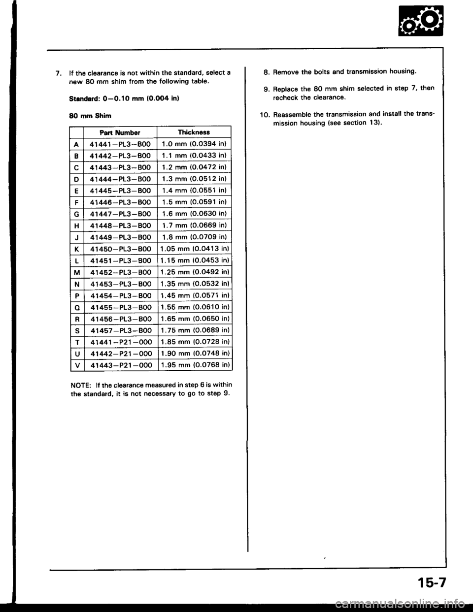
'llf the clearance is not within the standard, select a
new 80 mm shim from the following table.
Strndard: 0-O.1O mm (O.O04 inl
8O mm Shim
NOTE: lf tho clearance measuled in step 6 is within
th€ standard, it is not necessary to go to step 9.
Pan NumberThicknoss
A41441-PL3-BO01.O mm 10.0394 in)
B41442-PL3-BOO1.1 mm (O.O433 in)
41443-PL3- BOO1.2 mm (O.O472 in)
D41444-PL3-BOO1.3 mm (0.0512 in)
E41445-PL3-BO01.4 mm {0.0551 inl
f41446- PL3-BO01.5 mm (O.O591 in)
41447-PL3 -BOO1.6 mm (0.0630 in)
H41448-PL3- B001.7 mm (0.0669 in)
J41449-PL3- BO01.8 mm (0.0709 inl
K41450- PL3-BOO1.05 mm {o.o413 inl
L41451-PL3-BOO1.15 mm (0.0453 in)
M41452-PL3-BOO1.25 mm (O.O492 in)
N41453-PL3-BO01 .35 mm (0.0532 in)
P41454-PL3-BOO1.45 mm (0.0571 in)
o41455-PL3-BOO1 .55 mm (0.061O in)
R41456-PL3-8001.65 mm (0.O650 in)
s41457 - PL3-BOO1.75 mm (0.0689 in)
T41441-P21-OOO1.85 mm (0.0728 in)
U41442-P21-OOO1.90 mm (o.o748 in)
41443-P21-OOO1.95 mm (0.O768 in)
8.
9.
Remove the bolts and transmission housing.
Replace the 8O mm shim selected in step 7, thon
recheck the clearance.
Reassemble the transmission and install the trans-
mission housing {see section 13).10.
15-7
Page 575 of 1413
Differential (81 88l enginel
Oil Seal Installation
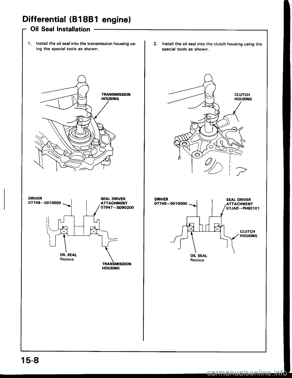
1. Install the oil seal into the t.ansmission housing us-
ing the special tools as shown
DRIVER07749-0010000
OIL SEALReplsce.
HOUSING
15-8
Install the oil seal into the clutch housing using the
soecial tools as shown.
DRIVER07749-0010000
OIL SEALReplace.
Page 576 of 1413
Differential (818C1 enginel
Special Tools ........
Differential
lllustrated Index .........
Backlash Inspection
Final Driven Gear Replacement ......
Tapered Roller Bearing Replacement.
Oil Seal Removal
Bearing Outer Race Replacement ...
Tapered Roller Bearing Preload
Adjustment
Oil Seal Installation
1 5-10
15-1 1
15-12
15-12
15-13
15-13
15-14
15-15
15-17
Page 577 of 1413
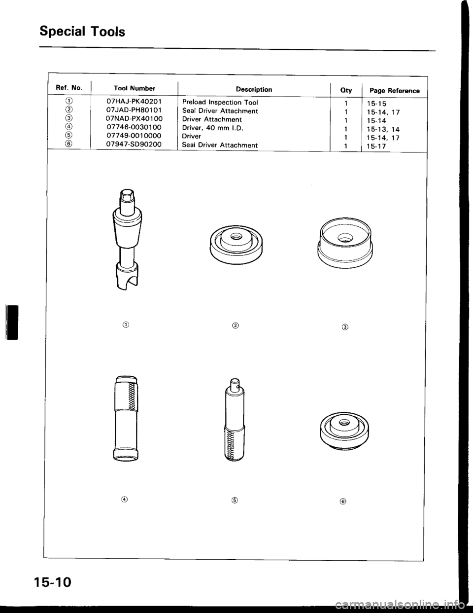
Special Tools
I
Ref. No. I Toot Number I DescriprionOty I Page Reference
o(
,a\
@
r.l
@
oTHAJ-PK40201
oTJAD-PH80101
oTNAD-PX40100
o7746-O030'l OO
o7749-OO10000
o7947-SD90200
Preload Inspection Tool
Seal Driver Attachment
Driver Attachment
Driver, 40 mm l.D.
Driver
Seal Drive. Attachment
I
I
1
15-1 5
1 5- 14
1 5- 14
15-13
1 5- 14
1 5-17
14
17
I
I
1
ort\aa\
@tl
$
s
15-10
Page 578 of 1413
Differential (B18C1 engine)
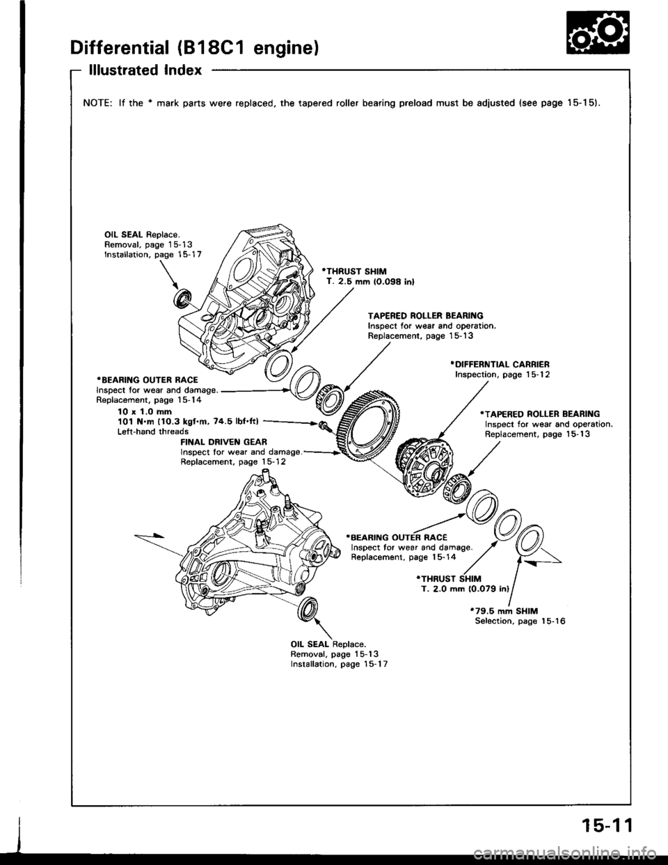
lllustrated Index
NOTE: lf the ' mark parts were replaced, the tape.ed roller bearing preload must be adiusted (see page 15-1 5).
OIL SEAL Replace.Removal, page 15-13Installation, page 15-17
'THRUST SHIMT. 2.5 mm lO.O98 inl
TAPERED ROLLER BEARINGInspect for wear and oporation.Replacement, page '15- 13
*BEARING OUTER RACEInspect tor wear and damage.Replacement. page 15-14
}DIFFERNTIAL CARRIERInspection, page 15-12
10 x 1.0 mm101 N.m 11O.3 kgt.m,74.5 lbt.ft)Left-hand threads
.TAPERED ROLLER BEARINGInspect for wear and operation.Replacement, page 'l5- 13FINAL DRIVEN GEARInspect lor wear and damage.Replacement, page 15- 12
T. 2.0 mm (0.079 inl
*79.5 mm SHIMSelection, page 15-16
OIL SEAL Replace.Removal, page'l5-13Installation, page 15-1 7
Page 579 of 1413
Differential (818C1 enginel
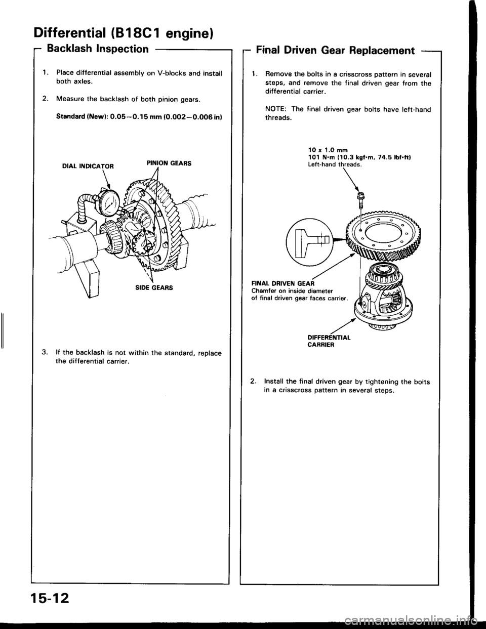
Backlash Inspection
Place ditterential assembly on V-btocks and instatlboth axles.
Measure the backlash of both pinion gears.
Standard (Now): 0.o5-o.15 mm {0.oo2-0.O06 in)
lf the backlash is not within the standard, reDlacethe differential carrier,
Final Driven Gear Replacement
1. Romove the bolts in a crisscross Dattern in several
steps, and remove the tinal driven gear f.om thedifferential carrier.
NOTE: The tinal driven gear bolts have lett-hand
threads.
10 x 1.O mm101 N.m (10.3 kgt.m, 74.5 lbf.ftlLeft-hand threads.
FII{AL DN|VEN GEARChamfer on inside diameterof linal driven g€ar taces carrier.
DIFFERETTTIALCABRIER
Install the final driven gear by tightening the bolts
in a crisscross pattern in several steps.
15-12
Page 580 of 1413
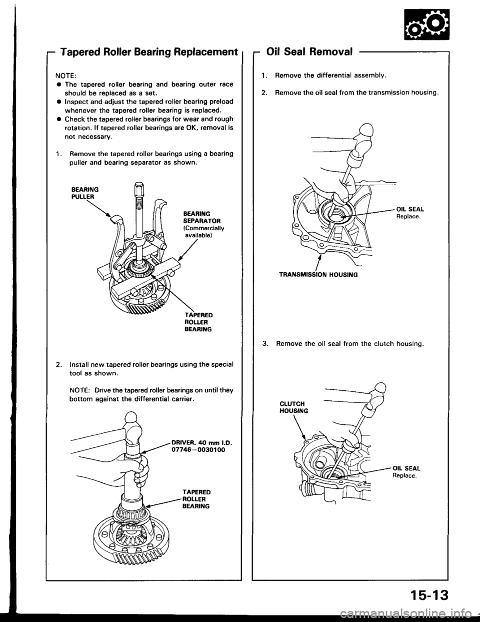
Tapered Roller Bearing Replacement
NOTE:
a The tapered roller bearing and bearing outer race
should be replaced as a set.
a Inspect and adjust the tapered roller bearing preload
whenevef the tapered rollef bearing is replaced.
a Check the tapered roller bearings tor wear and rough
rotation. lf tapered roller bearings are OK, removal is
not necessary.
1. Remove the tapered rolle. bearings using a bearing
puller and bearing separator as shown,
BEARING
BEARII{GSEPANATOR(Commercially
available)
Install new tapered roller bearings using the special
tool as shown.
NOTE: Drive the tapered roller bearings on until they
bottom against the differential carrier.
oilSealRemoval
1.Remove the differential assembly.
Remove the oil seal from the transmission housing.
3. Remove the oil seal from the clutch housino.
15-13
Trending: glass adjustment, charging, headlight bulb, MPG, boot, Steering wheel, gas type
