Block HONDA INTEGRA 1994 4.G Repair Manual
[x] Cancel search | Manufacturer: HONDA, Model Year: 1994, Model line: INTEGRA, Model: HONDA INTEGRA 1994 4.GPages: 1413, PDF Size: 37.94 MB
Page 1088 of 1413
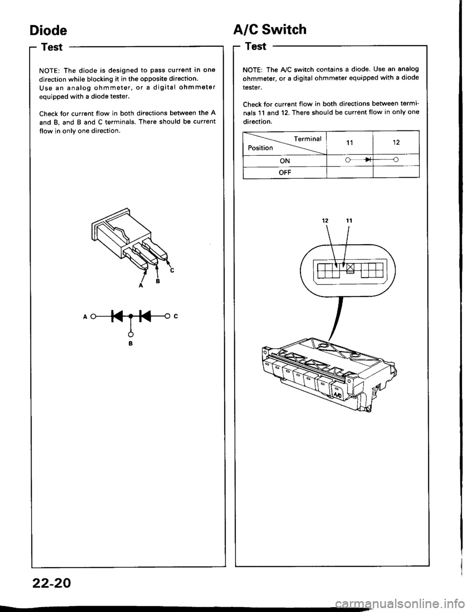
Diode
Test
NOTE: The diode is designed to pass current in one
direction while blocking it in the opposite direction.
Use an analog ohmmeter, or a digital ohmmeter
equipped with a diode tester.
Check for current flow in both directions between the A
and B. and B and C terminals. There should be current
flow in onlv one direction.
A/C Switch
Test
NOTE: The Ay'C switch contains a diode. Use an analog
ohmmeter, or a digital ohmmeter equipped with a diode
tester.
Check for current flow in both directions between termi
nals 11 and 12. There should be current flow in only one
direction.
Terminal
Position11
ONo
OFF
22-20
Page 1154 of 1413
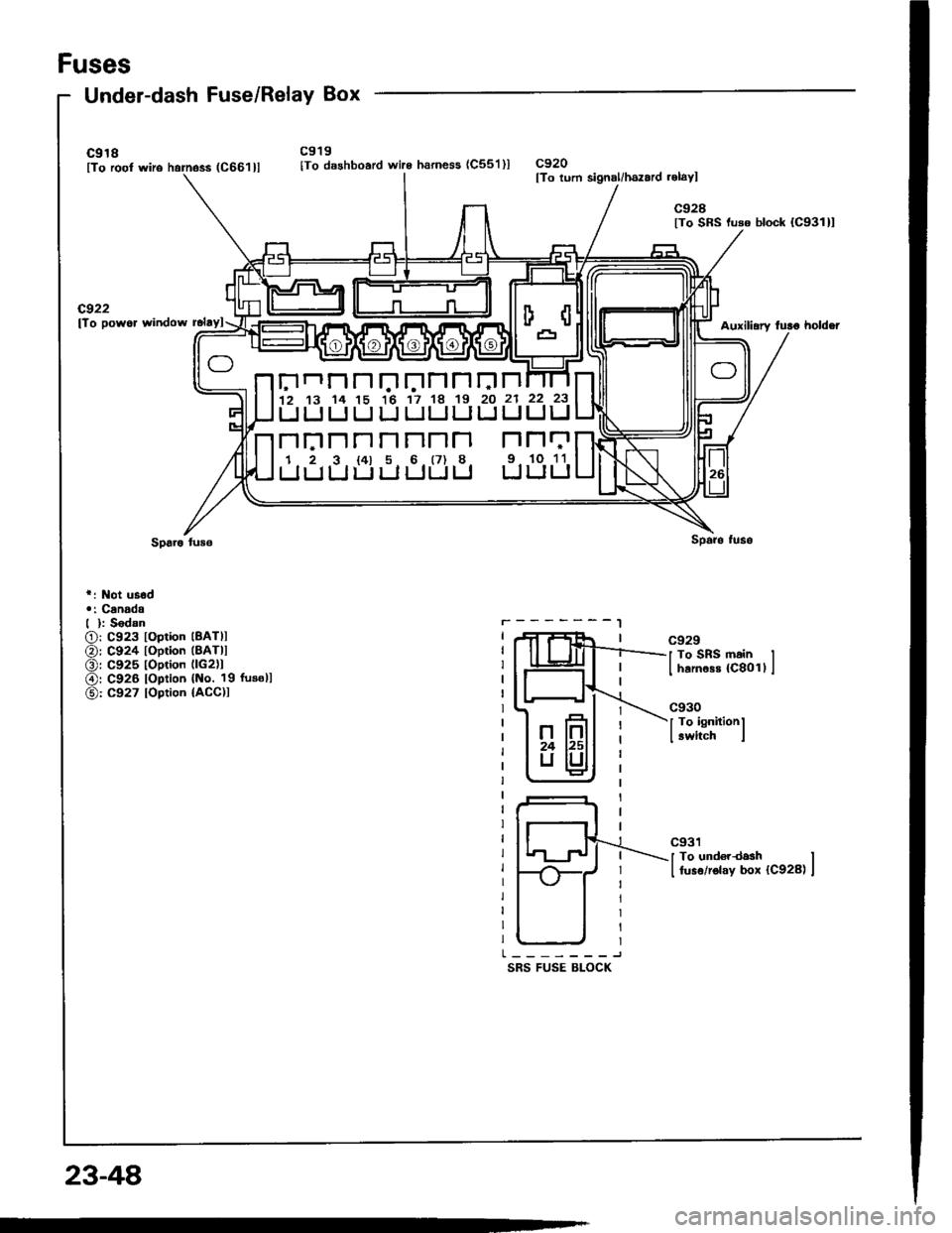
Fuses
Under-dash Fuse/Relay Box
c918lTo root wiro harness (C661llc919
lTo dashboard wire harness (C55'l )lc920lTo lurn signal/hszard .elayl
c928lTo SRS luso block {C931}l
cg22lTo powor window rclaylAuxili.ry fulo holdei
r: Not usod.: Canadd| ): S6dan
O: C923 loplion lBATll
@: C924 toption (BATll
O: C925 toption llc2)1
@r C926 loption {No. 19 fusoll
@: C927 loption {ACC)I
r.-------l
SRS FUSE BLOCK
c929
J To SRS main II harnass {C8011 I
c930
I To ignitionl
I switch i
c931
I To und€rdash II fuso/rolay box {C928) I
Elnnnr.'trJnnrJn12 13 14 15 16 17 18 19 20 21
UUIJUIJULJLILIIJ
n|:]nnnnnn r''l
1 2 3 t4l 5 6 (7) 8 9.
LIIJLIULJUUU U
22 23
UIJ
N11
10 11
LILI
23-48
Page 1212 of 1413
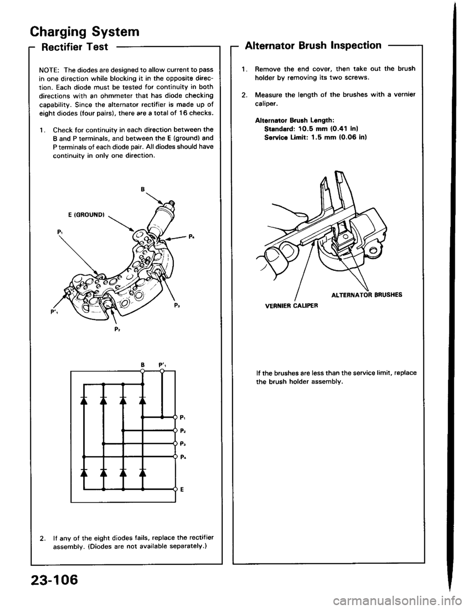
RectifierTest
NOTE: The diodes are designed to allow current to pass
in one direction while blocking it in the opposite direc-
lion. Each diode must be tested for continuitv in both
directions with an ohmmeter that has diode checking
capability. Since the alternator rectifier is made up of
eight diodes (four pairs), there are a total of '16 checks,
1. Check for continuity in each ditection between the
B and P terminals, and between the E (ground) and
P terminals of each diode pair. All diodes should have
continuity in only one direction,
lf any of the eight diodes tails, replace the rectifier
assembly. (Diodes are not available separately.)
Gharging System
Alternator Brush Inspection
Remove the end cover, then lake oul the brush
holder by removing its two screws
Measure the length of the brushes with a vernier
calioer.
Aliornatol Brush Longlh:
Standard: 10.5 mm (O.41 in)
Servic. Limit: 1.5 mm (O.06 in)
lf the brushes are less than the service limit, replace
the b.ush holder assemblv.
VERI{IEB CALIPEB
23-106
Page 1227 of 1413
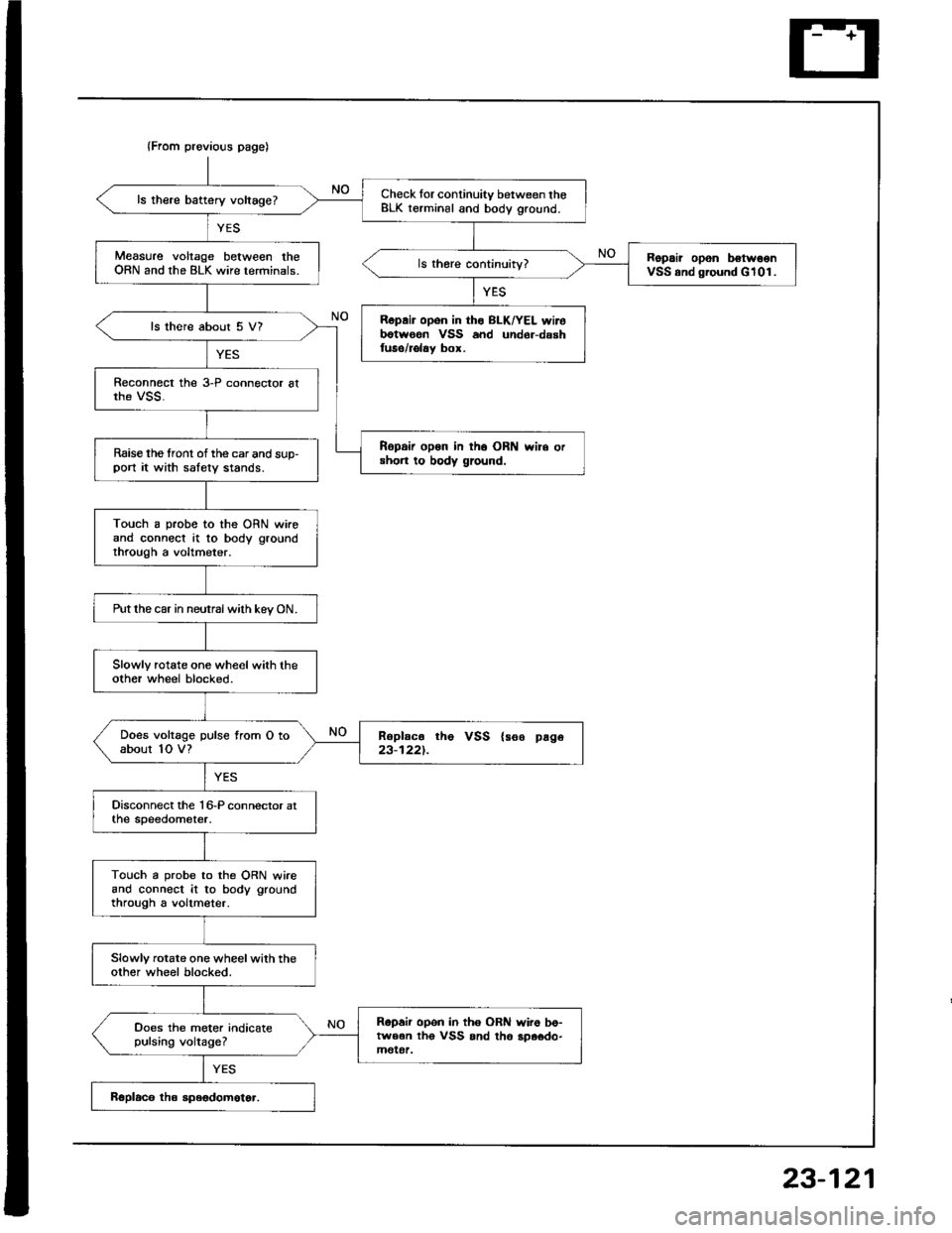
{From previous page)
Check tor continuity between theBLK terminal and body ground.ls there battery voltage?
Measure voltage between theORN and the BLK wire terminals.Ropair opon belw€onVSS and ground G101.
Ropair opon in tho BLKrYEL wirobotwoen VSS and undor-dsshluse/rolay box.
ls there about 5 V?
Ropair op6n in th6 ORN wire orshon to body ground.Raise the tront of the car and sup-port it with salety stands.
Touch a probe to the ORN wireand connect at to body groundthrough a voltmeter.
Putthe car in neutralwith kev ON.
Slowly rotate one wheel with theother wheel blocked.
Does voltage pulse from O toabout 1O V?Roplac. tho VSS {see page23-1221.
Touch a probe to the ORN wireand connect it to body groundthrough a voltmeter.
Slowly rotate one wheelwith theother wheel blocked.
Ropair opon in th6 OBil wire bo-tween tho VSS and th6 3p.odo-molgt.
Ooes the meter indicatepulsing voltage?
23-121
Page 1237 of 1413
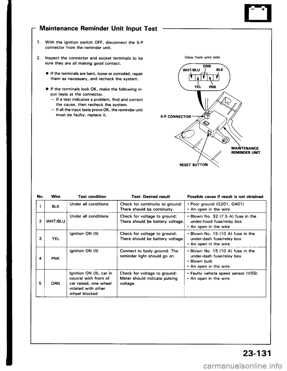
Maintenance Reminder Unit Input Test
1.With the ignition switch OFF, disconnect the 5-P
connector from the reminder unit,
Inspect the connector and socket terminals to be
sufe they are all making good contact.
a lJ the terminals are bent, loose orcorroded, repair
them as necessary, and recheck the svstem.
a It the terminals look OK, make the following in-
Put tests at the connecto..- lf a test indicates a problem, tind and correct
the cause, then recheck the system.- It allthe input tests prove OK, the reminder unit
must be taulty; replace it.
View trom wire side
No.WireTost condltionTest: DaEired rasultPossibl€ cause if result is not obtained
IBLKUnde. all conditionsCheck for continuity to ground:
There should be continuitv.
. Poor ground (G201, G4O1). An open in the wire
WHT/BLU
Under all conditionsCheck tor voltage to ground:
There should be battery voltage
. Blown No. 32 (7.5 A) fuse in the
under-hood tuse/relay box. An open in the wire
YEL
lgnition ON (lllCheck for voltage to ground:
There should be batte.y voltage
. Blown No. 15 (1O A) fuse in the
under-dash fuse/relay box. An open in the wire
4PNK
lgnition ON (ll)Connect to body ground; The
reminder light should go on.
Blown No. 15 (1O A) tuse in the
under-dash fuse/relay box
Blown bulb
An open in the wire
EORN
lgnition ON {ll), car in
neutral with lront ol
car raised, one wheel
rotated with other
wheel blocked
Check for voltage to g.ound:
Meter should indicate pulsing
voltage.
. Faulty vehicle speed sensor (VSS)
. An oDen in the wire
23-131
Page 1249 of 1413
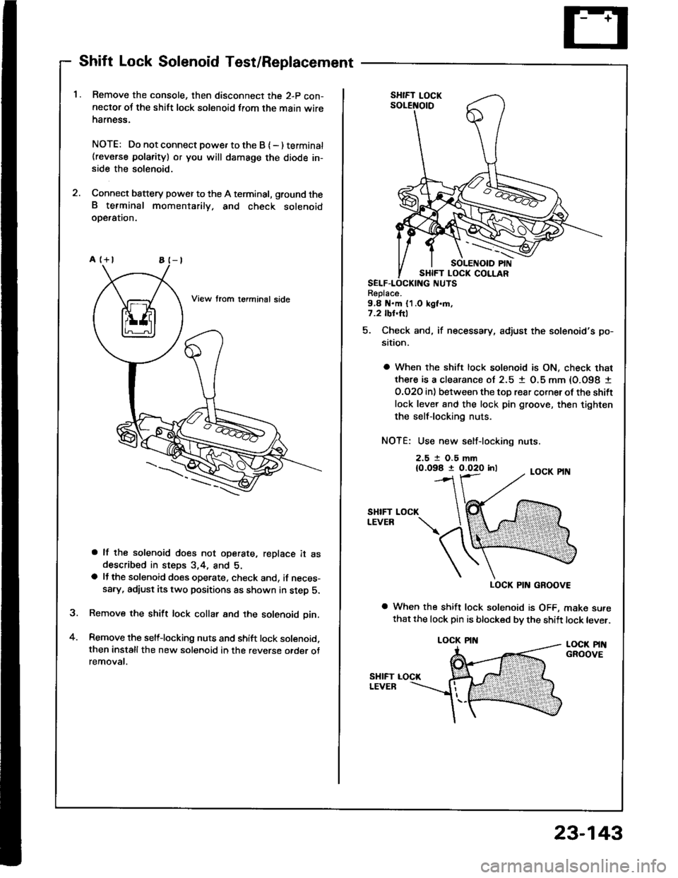
Shift Lock Solenoid Test/Replacement
Remove the console, then disconnect the 2-p con-neclor oJ the shift lock solenoid from the main wireharness.
NOTE: Do not connect powe. to the B { - ) terminat(reverse polarity) or you will damsge the diode in-side the solenoid.
Connect battery power to the A terminal, ground theB terminal momentarily. and check solenoidoDeralron.
a lf the solenoid does not operate, replace it asdescribed in steps 3,4, and 5.a lJ the solenoid does operate, check and, if neces-sary, adiust its two positions as shown in step 5.
Remove the shift lock collar and the solenoid pin.
Remove the selflocking nuts and shift lock solenoid,then installthe new solenoid in the reverse otder otremovat.
a
Replace.9,8 N.m {1.0 kgl.m,7.2 tbl.hl
5. Check and, if necessary, adjust the solenoid's po-
sition.
a When the shift lock solenoid is ON, check that
there is a clearance ol 2.5 1 O.5 mm {O.O98 I
O.O2O in) between the toD rear corner ot the shift
lock lever 8nd the lock pin groove, then tighten
the selflocking nuts.
NOTE: Use new self-locking nuts.
2.5 t O.5 mm{0.098 t 0.020 inl
SHIFTLEVEB
LOCK PIN GROOVE
a When the shift lock solenoid is OFF, make surethat the lock pin is blocked bv the shift lock lever.
LOCK PINGROOVE
LOCK
LOCK PIN
23-143
Page 1369 of 1413
l.
2.
1.
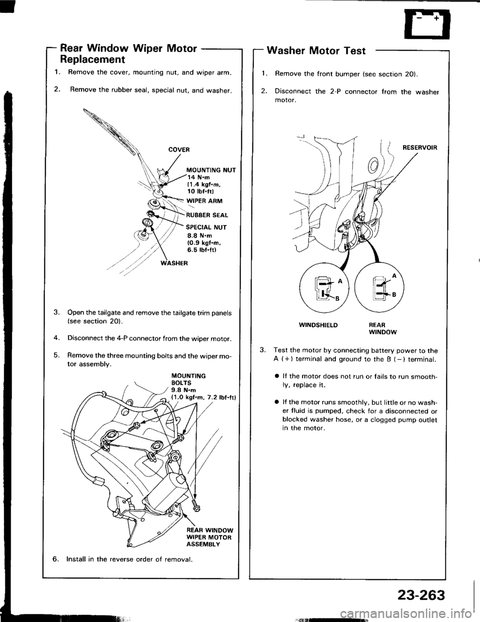
Rear Window Wiper Motor
Replacement
Remove the cover, mounting nut, and wiper arm.
Remove the rubber seal, special nut, and washer.
MOUNTING NUT
Washer Motor Test
Remove the front bumper (see section 20).
Disconnect the 2-P connector lrom the washer
motor.
RESERVOIR
WINDSHIELD
14 N.m11.4 kgf.m,10 tbt.trl
WIPER ARM
RUBBER SEAL
SPECIAL NUT
8.8 N.m{0.9 kgt'n,6.5 rbt.fr)
MOUNTINGBOLTS9.8 N.m(1.O kgf.m, 7.2 lbf.ttl
-4
)
Open the tailgate and remove the tailgate trim panels(see section 20).
Disconnect the 4-P connector from the wiper motor.
Remove the three mounting bolts and the wiper mo-
tor assembly.
REARwrNDow
Test the motor by connecting battery power to the
A ( + ) terminal and ground to the B (- ) terminal.
a ll the motor does not run or fails to run smooth-
ly, replace it.
a lf the motor runs smoothly, but little or no wash-
er fluid is pumped. check for a disconnected orblocked washer hose, or a clogged pump outlet
in the motor.
6, Install in the reverse order o{ removal.
23-263