Block HONDA INTEGRA 1994 4.G User Guide
[x] Cancel search | Manufacturer: HONDA, Model Year: 1994, Model line: INTEGRA, Model: HONDA INTEGRA 1994 4.GPages: 1413, PDF Size: 37.94 MB
Page 145 of 1413
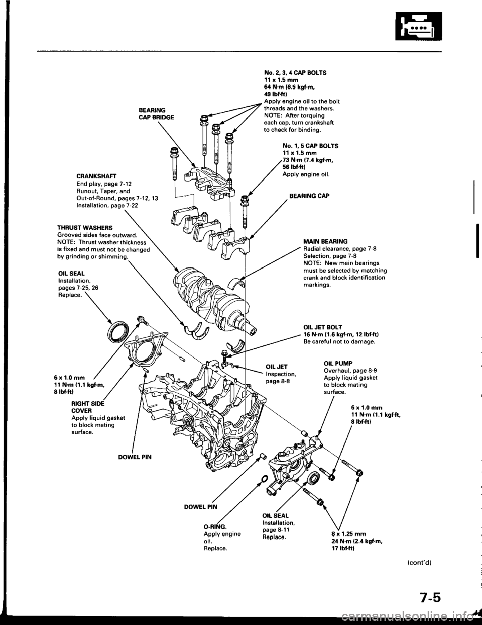
BEARINGCAP BRIDGE
No. a 3, /a CAP BOLTSll x 1.5 mm64 N.m {6.5 kgt m,49 tbf.ftlApply engine oilto tho boltthreads and the washers.NOTE: Aftertorquingeach cap, turn crankshaftto check for binding.
No. 1,5 CAP BOI-TS11 x 1.5 mm73 N.m {7.4 kgf.m,56 tbt'ft|Apply engine oil.
BEARING CAP
CRANKSHAFTEnd play, page 7-12Runout, Taper, andOut-of-Round, pages 7'12. 13Installation, page 7-22
YHRUST WASHERSGrooved sides lace outward.NOTE: Thrust washer thicknessis fixed and must not be chano€d
MAIN BEARINGRadial clearance. page 7 8S6l€ction, page 7-8NOTE: New main bearingsmust be selected by matchingcrank and block identificationmarxrngs.
OIL JEI BOLY16 N.m 11.6 kg{'m, 12lbtftlBe caretul not to damage.
OIL PUMPOverhaul, page 8-9Apply liquid gasket
to block matingsurface.
OIL SEALInstallation,pages 7-25, 26
11 N.m 11.1 kgt m,8 lbf ftl
Replace.
6r1.0mm
OIL JETInspection,page 8-8
OIL SEALInstellelion,page 8-11Replace.
RIGHT SIDECOVERApply liquid gasketto block matingsurface.
6x1.0mm11 N.m {1.18 rbf.ftlkSf.ft,
DOWEL PIN
DOWEL PIN
O.RING.Apply engineorl.Replace.
8 x 1.25 mm24 N.m {2.4 kgt m,17 tbtft)
(cont'd)
7-5
Page 147 of 1413
Flywheel and Drive Plate
Replacement
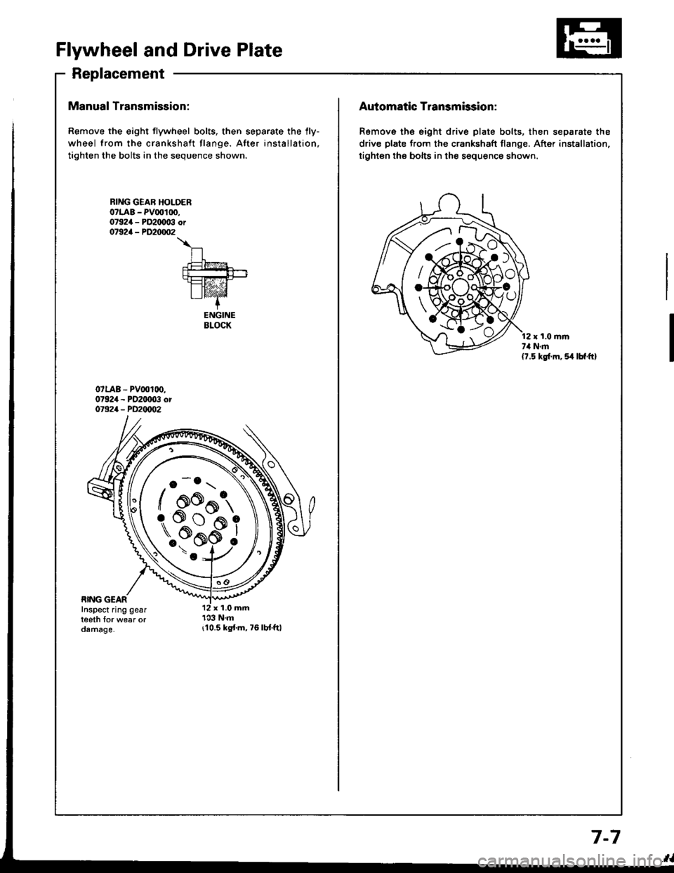
Manual Transmission:
Remove the eight flywheel bolts, then separate the lly-
wheel from the crankshaft flange. After installation,
tighten the bolts in the sequence shown.
r10.5 kgi.m,76lbt.ftl
RING GEAR HOLOERo?LAB - PV00100,07924 - PO2IX)03 or07924 - PD20/m�2
\
n.t=?4
fut!!-+-rt=tz-21I lvaz'Z-+
ENGINEBLOCK
o -o.r \
/ oo^t,
\..?bi
/ AK{:{AAo
rs#*ffi_9
Automatic Transmission:
Remove th€ eight drive plate bolts, then separate the
drive plate from the crankshaft flange, After installation,
tighten the bolts in the sequence shown.
r t.0 mmt,l N.m(7.5 kg{.m, 54 lbf.ft}
7-7
Page 148 of 1413
Main Bearings
Clearance
To check main bearing-to-journal oil clearance,
remove the main caps and bearing halves.
Clean each main journal and bearing half with a
clean shop towel.
Place one strip of plastigage across each main iour-
nal.
NOTE: lf the engine is still in the car when you bolt
the main caD down to check clearance, the weight
of the crankshaft and flywheel will flatten the plasti-
gage further than just the torque on the cap bolt,
and give you an incorrect reading. Fot an accurate
reading, support the crank with a iack under the
counterweights and check only one bearing at a
trme.
Reinstall the bearing caps and cap bridge (818C1
engine only) then torque the bolts.
81881 engine:77 N'm (7.8 kgf'm,56lbl'ft)
818C1 engine:
No. 1,5 cap bolts 73 N'm (7.'l kgt'm,56lbf'ftl
No. 2, 3, 4 cap bolts 6a N'm (6.5 kgf'm, 49 lbf'ftl
NOTE: Do not rotate the crankshaft during inspec-
tron,
Remove the cap bridge (818C1 engine only), caps
and bearings again, and measure the widest part oJ
the plastigage.
Main Bearing-to-Journal Oil Cl€arance:
Standard (Newl:
No. 1, 2, 4, 5: 0.024 - 0.042 mm
10.0009 - 0.0017 inl
Service Limit: 0.050 mm {0.0020 inl
No. 3:0.030 - 0.0,18 mm(0.0012 - 0.0019 inl
Ssrvice Limit: 0.060 mm {0.0024 inl
PLASTIGAGE STNIP
lf the plastigage measures too wide or too narrow,
(remove the engine if it's still in the car), remove the
crankshaft. and remove the upper half of the bear-
ing. Install a new. complete bearing with the same
color code (select the color as shown in the right
column), and recheck the clearance.
CAUTION: Do not file, shim, or scrapo ihe bo.rings
or the caps to adiust clearance.
lf the plastigage shows the clearance is still incor-
rect, try the next larger or smaller bearing (the color
listed above or below that one), and check again.
NOTE: lf the Droper clearance cannot be obtained
by using the appropriate larger or smaller bearings,
reolace the crankshaft and start over.
Selection
CAUTION: lf ths codes are indeciphorable becau3o ot
an lccumulation ol dirt and dust, do not gcrub thgm
with a wirs brush or gcrapsr. Clean them only with 3ol-
vont or doisrggnt.
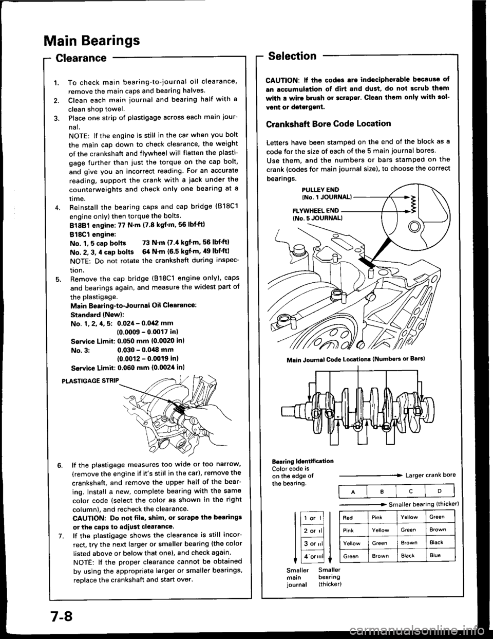
Crankshaft Bore Code Location
Letters have been stamped on the end of the block as a
code for the size of each of the 5 main journal bores
Use them, and the numbers or bars stamped on the
crank (codes for main journal size), to choose the correct
bearings.
B..ring ld.ntificrtionColor code is
on the edge otthe bearang.Larger crank Dore
Mlin Joumal CodG Locttion3 (Numbors or gaBl
IcD
tr;;lIl
Itr-tl
lE;tl I tlHlt
I Lo.""li L
Smaller Smallermsin bearingjournal (thicker)
-------.r> smaller bearing (thicker)
G'een
Gre€^
GreenBlacr
GreenElackBlue
7-8
Page 153 of 1413
Out-ot-Round and Taper
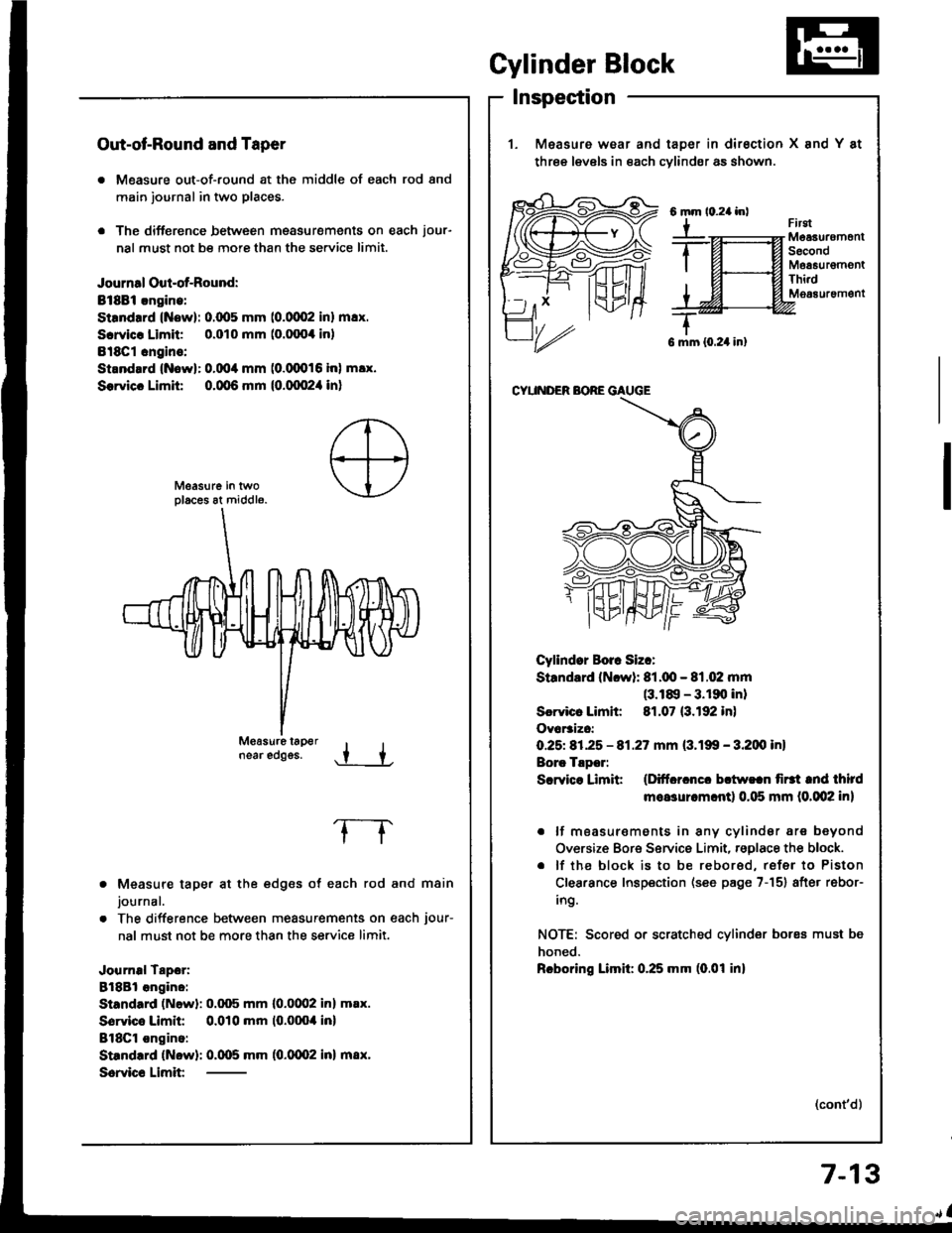
. Measure out-of-round at the middle of each rod and
main journal in two places.
. The difference between msasurements on each jour-
nal must not be more than the se.vice limit.
Journal Oul-of-Round:
Bt8Bi.ngine:
Strndrrd (Now): 0.(x15 mm (0.0002 inl m!x.
Scrvicr Limit 0.010 mm (o.fixx inl
Bl8Cl cngins:
Strnd.rd {Nowl: 0.004 mm (0.(XD16 inl m!x.
Sorvicc Limit 0.qt6 mm {0.qx!2,1 in}
near edggs..t +
Measure taper at the edges of each rod and main
journal.
The difference between measurements on each jour-
nal must not be more than the service limit.
Journal Tapor:
8l8Bl angino:
Standard (Newl: 0.q)5 mm l0.0(Xl2 inl m.x.
Sorvico Limit 0.010 mm (0.0004 inl
BlSCl ongino:
Standrrd (Now): 0.005 mm (0.0002 inl m8x.
Scrvic€ Limit
frrgtMeaauremonlSecondMoa6urgmontThi.dM063uremgnt
G mm {0.24 in}
CYUNDER BORE GAUGE
Cyllndor Borr Siz.:
Standard (Ncwl: 81.q!- 81.02 mm(3.18, - 3.190 inl
Scrvicr Limh: 81.07 (3.192 in)
Ovar3izc:
O.25t 81.25 - 81.27 mm (3.199 - 3.200 inl
Borc Tlpor:
Scrvice Limit (Ditfcrcncc bctw!.n firtt tnd third
moasurcm.ntl 0.115 mm (0.002 in)
. lf moasur€ments in any cylindsr are beyond
Oversize Bore Service Limit, rsglace the block.
. lf the block is to be rebored, refer to Piston
Clearance Inspection (see page 7-151 after rebor-
ing.
NOTE: Scored or scratched cylinder bores must be
honed.
Rcboring Limil: 0.25 mm (0.01 inl
(cont'd)
Gylinder Block
Inspection
1. Measure wear and taDer in dirsction X and Y at
three levels in each cvlindsr as shown.
6mm
Y
7-13
Page 154 of 1413
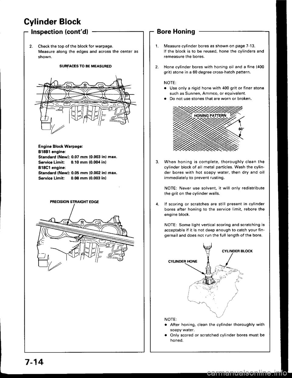
Cylinder Block
Inspection (cont'dl
2.Check the top of the block for warpage.
Measure along the edges and across the center as
snown.
SURFACES TO BE MEASURED
Engine Block Warpsgc:
81881 ongine:
Standard lNewl: 0.07 mm {0.003 inl max.
Service Limil: 0.10 mm {0.00,1inl
B18Cl engine:
Standard (New): 0.05 mm 10.002 inl max.
Service Limit 0.08 mm {0.003 inl
Measure cylinder bores as shown on page 7-13.
lf the block is to be reused, hone the cylinders and
remeasure the bores.
Hone cylinder bores with honing oil and a fine (400
grit) stone in a 60 degree cross-hatch pattern.
NOTE:
. Use only a rigid hone with 400 grit or finer stone
such as Sunnen, Ammco, or equivalent.
a Do not use stones that are worn or broken.
When honing is complete, thoroughly clean the
cylinder block of all metal panicles. Wash the cylin-
der bores with hot soapy water, then dry and oil
immediately to prevent rusting.
NOTE: Never use solvent, it will only redistribute
the grit on the cylinder walls.
lf scoring or scralches are still present in cylinder
bores after honing to the service limit, rebore the
engine block.
NOTEr Some light venical scoring and scratching is
acceptable if it is not deep enough to catch your fin-
gernail and does not run the full length of the bore.
CYLINDER HONE
. After honing, clean the cylinder thoroughly with
soapy water.
. Only scored or scratched cylinder bores must be
noneo.
7-14
Page 155 of 1413
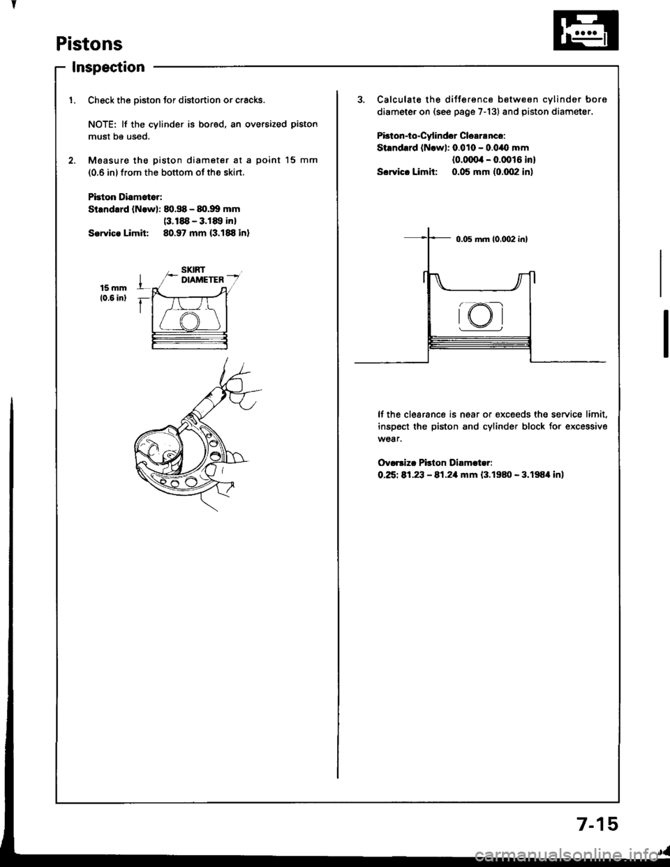
Pistons
Inspection
1. Check the oiston for distortion or cracks.3, Calculate the difference betw€on cvlinder bore
diameter on (see page 7-13) and piston diametsr.
Pbton-io"Cy'indor Clea18nco:
Stsndard (Nrwl: 0.010 - 0.0/O mm
{o.ofira - 0.0016 in}
S.rvic. Limit: 0.05 mm {0.002 in)
NOTE: lf the cylinder is bored, an oversized piston
must be used,
2. Moasur€ the piston diameter at a point l5 mm
(0.6 in) from the bottom of the skin.
Pbion Diamat6r:
Standard lNowl: 80.S - 80.99 mm(3.188 - 3.189 inl
Sorvica Limit 80.97 mm (3.188 in)
lf the clearance is near or €xc€eds the service limit,
inspect the piston and cylinder block for excessive
wear.
Ov.rsizc Pilton Diamcter:
O.25t 81,23 - 81.21|rnm {3.1980 - 3.198'l in)
rKI
7-1
Page 157 of 1413
I
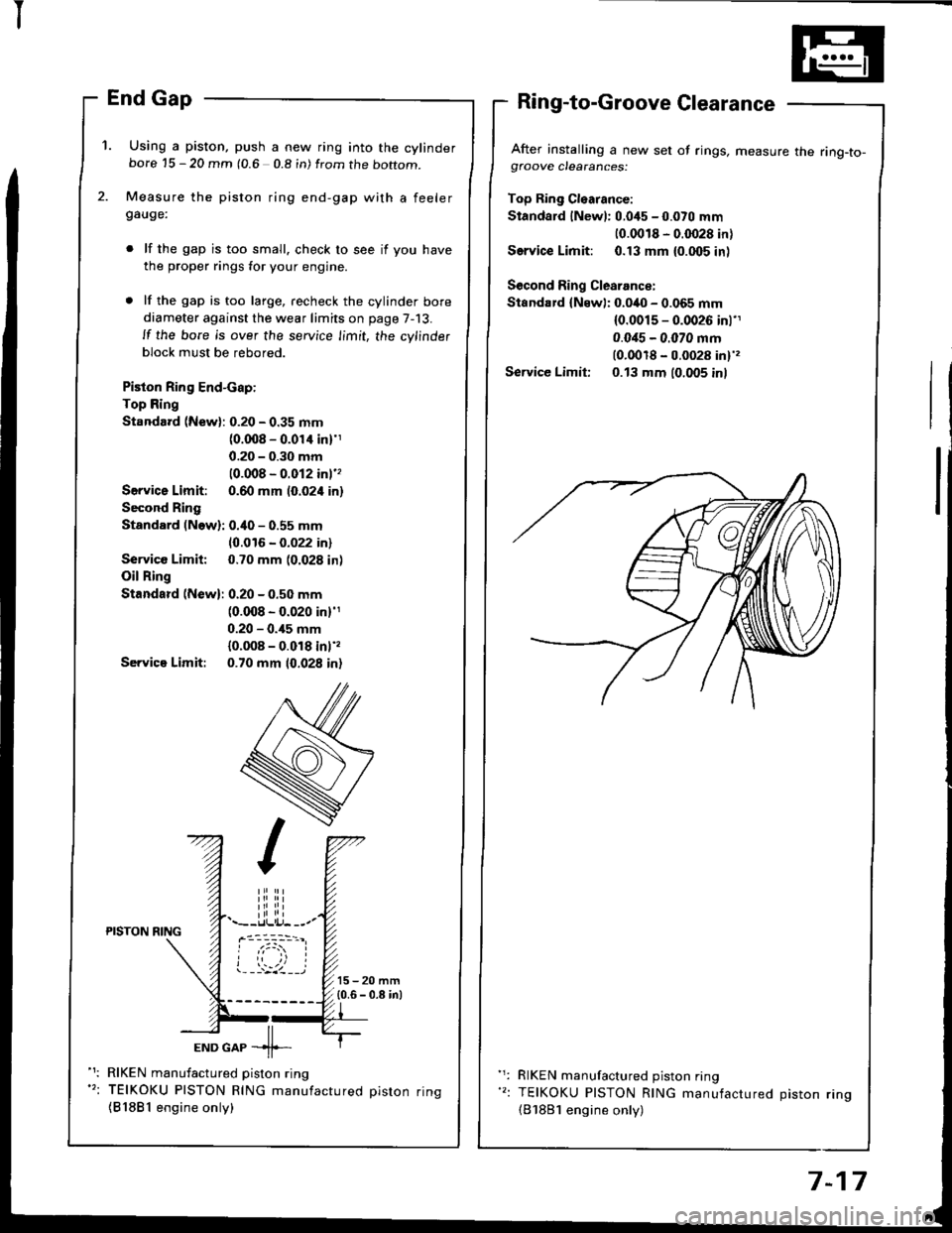
'1. Using a piston, push a new ring into the cylinderbore 15 - 20 mm (0.6 0.8 in) from the boftom.
Measure the piston ring end-gap with a feelergauge:
lf the gap is too small. check to see if you have
the proper rings for your engine.
lf the gap is too large, recheck the cylinder bore
diameter against the wear limits on page 7-13.
ll the bore is over the service limit, the cylinder
block must be rebored.
Piston Ring End-cap:
Top Ring
Standard (New): 0.20 - 0.35 mm(0.008 - 0.01'l inl'1
0.20 - 0.30 mm
10.008 - 0.012 inl''
Servica Limit: 0.60 mm (0.024 in)
Second Ring
Standard (Now): 0.40 - 0.55 mm
10.016 - 0.022 in)
Service Limit: 0.70 mm (0.028 in)
Oil Ring
Standard (New): 0.20 - 0.50 mm(0.008 - 0.020 in)'1
0.20 - 0.,15 mm
{0.008 - 0.018 inl',
Servica Limit: 0.70 mm 10.028 in)
After installing a new set of rings, measure the ring-to-gfoove clearances:
Top Ring Cl€arance:
Standard lNewl: 0.045 - 0.070 mm
10.0018 - 0.0028 in)
Service Limit: 0.13 mm {0.005 inl
Second Ring Clearance:
Standard {Newl: 0.040 - 0.065 mm(0.0015 - 0.0026 inl'1
0.0i15 - 0.070 mm(0.0018 - 0.0028 in)',
Service Limit: 0.13 mm (0.005 inl
iliiii.--r.llli.j- --.-PISTON NING
ioi
---'z llEND GAP -11--
RIKEN manufactured piston ring
TEIKOKU PISTON RING manufactured oiston rinq
{81881 engine only)
RIKEN manufactured piston ring
TEIKOKU PISTON RING manufactured Diston rino(B'1881 engine only)
7-17
Page 162 of 1413
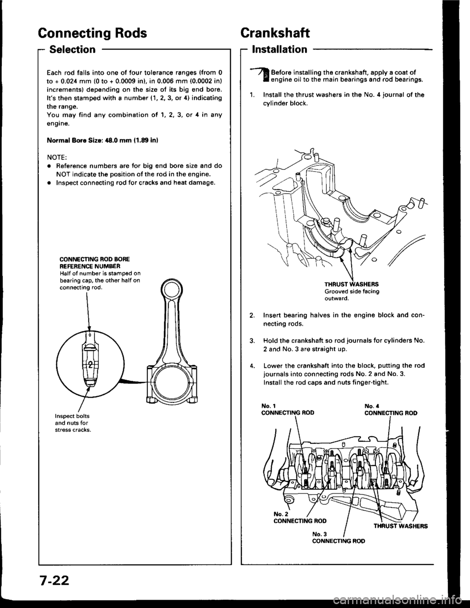
Connecting Rods
Selection
Each rod falls into one of four tolerance ranges (from 0
to + 0.024 mm (0 to + 0.0009 inl, in 0.006 mm {0.0002 in)
increments) depending on the size ot its big end bore.
It's then stamped with a number (1,2,3, or 4) indicating
the range.
You may find any combination ol 1, 2, 3, or 4 in any
engane.
Normsl Boro Sizoi ,18.0 mm 11.89 inl
NOTE:
a Reference numbers are Jor big end bore size and do
NOT indicate the position of the rod in the engine.
. Inspect connecting rod for cracks and heat damage.
CONNECNNG ROD BOREREFERENCE NUMBERHalf oI number is stamped onbearing cap. th€ other halfonconnecting rod.
Crankshaft
lnstallation
Before installing the crankshaft. apply a coat ofengine oil to the main bearings and rod bearings.
1. Install the thrust washers in the No. 4 iournsl of the
cvlinder block.
Grooved side tacingo!tward
Insert bearing halves in the engine block and con-
necting rods.
Hold the crankshaft so rod journals for cylinders No.
2 and No.3 are straight up.
Lower the crankshaft into the block. putting the rod
journals into connecting rods No.2 and No.3.
Install the rod caps and nuts finger-tight,
CONNECNNG ROD
7 -22
Page 164 of 1413
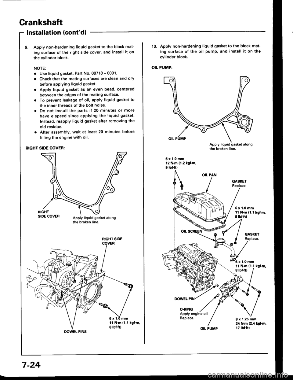
Grankshaft
Installation (cont'd)
9. Apply non-hardening liquid gasket to the block mat-
ing surface of the right side cover, and install it on
the cylinder block,
NOTE:
. Use liquid gasket, Part No. 08718 - 0001.
. Check that the mating surfaces are clean and dry
before applying liquid gasket.
. Apply liquid gasket as an even bead, centered
between the edges of the mating surface.
. To prevent leakage of oil, apply liquid gasket to
the inner threads of the bolt holes.
. Do not install the parts if 20 minutes or more
have elapsed since applying the liquid gasket.
Instead, reapply liquid gasket after removing the
old residue.
. After assembly, wait at least 20 minutes before
filling the engine with oil.
RIGHT SIDE COVER:
RIGHT SIDE
DOWEL PINS
7-24
R6plac€.
OIL PUMP
10. Apply non-hardening liquid gasket to the block mat-
ing surface of the oil pump, and install it on the
cvlinder block.
OIL PUMP:
DOWEL PIN
O.RING
6x1,0mmtl N.m {1.1 kgr'm.8 tbf.ftl
6x1.0mm
8 x 1.25 mm2il l$m l2.ia kg[.m.1t rbf.ftl
11 N.m {1.1 tgl.m,
Page 165 of 1413
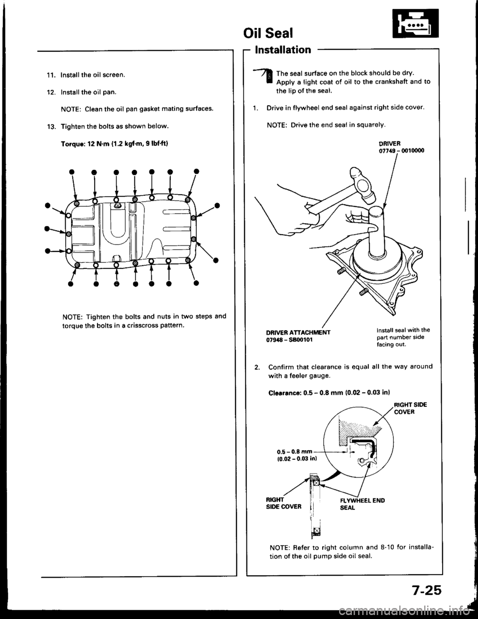
11.lnstallthe oil screen.
Installthe oil pan.
NOTE: Clean the oil pan gasket mating surfaces.
Tighten the bolts as shown below.
Torque: 12 N.m {1.2 kgf.m, 9 lbf'ft)
NOTE: Tighten the bolts and nuts in two steps and
toroue the bolts in a crisscross pattern
1'�I
Oil Seal
lnstallation
The seal surface on the block should be dry.
Apply a light cost of oil to the crankshaft and to
the liD of the seal.
Drive in flywheel end seal against right side cover.
NOTE: Drive the end seal in squarely.
DRIVER07t,49 - (xll(xtoo
2. Confirm that clearance is equal all the way around
with a fe€ler gauge.
Cler.6nce: 0.5 - 0.8 mm (0.02 - 0.03 inl
RIGHT SIDECOVER
NOTE: Reter to right column and 8-10 lor installa-
tion of the oil pump side oil seal.
lnstall sealwith thepart number sidetacing out.
7-25