Block HONDA INTEGRA 1994 4.G Owner's Guide
[x] Cancel search | Manufacturer: HONDA, Model Year: 1994, Model line: INTEGRA, Model: HONDA INTEGRA 1994 4.GPages: 1413, PDF Size: 37.94 MB
Page 258 of 1413
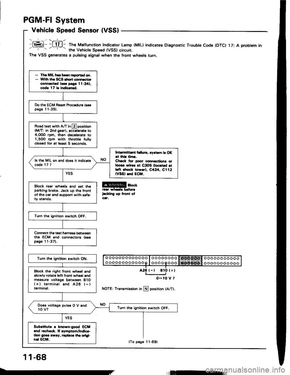
PGM-FI System
Vehicle Speed Sensor (VSS)
- _-_f_-., \-=1_ -
It6l- -l tl l- The Maltuncrion Indicator Lamp (MtL)' ths Vehiclo SD6sd (VSS) circuit.
indicateE Diagnostic Trouble Code IDTC) 17: A problem in
a25 {-t
The VSS generates a pulsing signal when the front wheels turn.
@4""rr.r whadr b.lor.
l.d.lnC up tront olcat,
NOTE: Transmission in llj position lA/Tl.
- Tha mll hs b..n ltgortld o.r.* Yvlrh th. Sc]S $o.r coi[cto.connast.d l... ploa I l -341,
cod! 17 i. Indlc.i.d.
Do the ECM Basot Procodur6 16€€pag€ I I -351.
Road rosr whh A/T in13 positaon
{M/T: in 2nd O6ar), accol6rat6 to4,OOO rpm, thon d6c6l6,ate to1,5OO .pm with th.ottlo fullyclosod tor at loast 5 s6conds.
Int rmltllrt t llur., .yrtam b O|(.t drlr drr.Chcct lor poor conicctlon! oalootc wl... !t C3O5 0ocrtad rtLtt rhod. torr.l, eA24. C112IVSA) .nd ECil.
ls th6 MIL on and doos it indic.t6code 'l7 ?
Block roar whe€19 and 5st th6parking brsko. Jsck up th€ f.ontof the c6. and support with saf€-iy standa.
Turn the ignition Bwitch OFF.
Connect tho t€st hamos3 b€tw€€ntho ECM ond connoctora {as€pag6 11-37).
Tu.n th€ ignitioh switch ON.
Block the .ight lront whoel andalowly rctato loft tront wh6ol andm6asur6 voltago b€twoon BlO{+) torminal and A26 l-}terminal.
Doss voltago puleo O V and10 v?Tu.n th€ ignition switch OFF.
Sub|tllul. ! knosn{ood ECMlnd r!ch.ck. lt .Vmgiom/lndlc.-tlon g@.. .w.y, r.pLca di. orlgl-n.l ECM.
ato l+l
0- 10 V ?
11-68
lTo p6ge 1 1-691
llEur
Page 259 of 1413
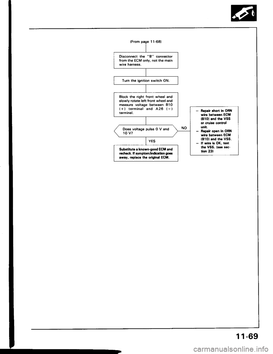
Disconnect the "B" connectorfrom the ECM only, not the mainwile hatness.
Turn the ignition switch ON.
Block tho right front who€l andslowlv rotate l6ft front wheel andm€asure voltage between 8'l Ol+) terminal and A26 (-)
terminal.- Roo.ir lhort in ORt{wire belween ECM18101 tnd rhs VSSor cruia6 controlunit.- ncp.i. op€n in ORI{wira botwoan ECM(8101 and the vSS.- It wir. i! OK, totttho vSS. lsoc aec-tion 231
Doos voltage pulso O V and'to v?
SubrtituL . known-good ECil lndEch.ck. fi lynptom/ndcltbn gp..
rw!y, .rpleco lh. original ECM.
(From page 1 1-68)
1 1-69
Page 313 of 1413
Intake
Intake
Air
Air
System
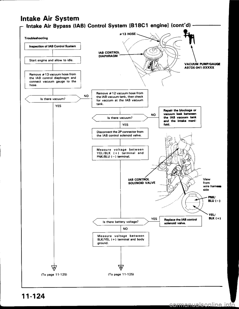
Bypass (lAB) ControlSystem tBl8C1 enginel (cont'dl
Troublcahooting
VACUUII PUMP/GAUG€A973X-041-XXXXX
fromwiro haanasid€
PI{K/BLU I-I
YEI/aLK l+l
tA8 COI{TROLDIAPHRAGM
Insp€ction of IAB Conltol Sytt.m
Start engino and allow to idle.
R€move # 13 vacuum hose tromthe IAB control diaph.agm andconnect vacuum gauge to thehose.
R€move # 12 vacuum hose fromth€ IAB vacuum tank, then checktor vaccum at the IAB vacuumtank.
Rcplir lh. block.g. otvacuufi laak boiwaaotha IAB vacuum tanklnd th. intlk m!ni-fold.
Disconnect the 2P conn€ctor lromthe IAB control solenoid valve.
Measure voltage betweenYEL/BLK (+l torminal andPNK/8LU l-) terminsl.
ls thoro battery voltage?
Measure voltage b€twee nBLK^|/EL (+) torminal and bodyground.
IAB CONTBOLSOLENOID VALVE
Page 328 of 1413
(F.om pdge 1l-138)
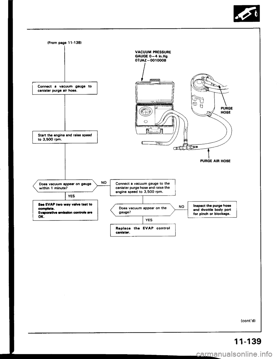
Connoct a vlcuum gaugo tocaniator purg! lir ho!o.
Stsn tho onginc lnd rai!. spo€dto 3,50O rpm.
Connect a vacuum gauge to thecsnister puag6 hos6 and raise thesngin€ spe€d to 3,500 rpm.
Do€a vocuum opp€ar on gougo
within 'l minuto?
Saa EVAP tso {ay vdv. t.!t ioconrDbta.Evapoardva ambdon coartaoL |.|ox.
Inapoct tha purga hosoand drronl. body potl
for pinch or blocklga.
VACUUM PRESSUREGAUGE O-4 In.HgoTJAZ-OOIOOOB
PURGE AIR HOSE
(cont'd)
11-139
Page 346 of 1413
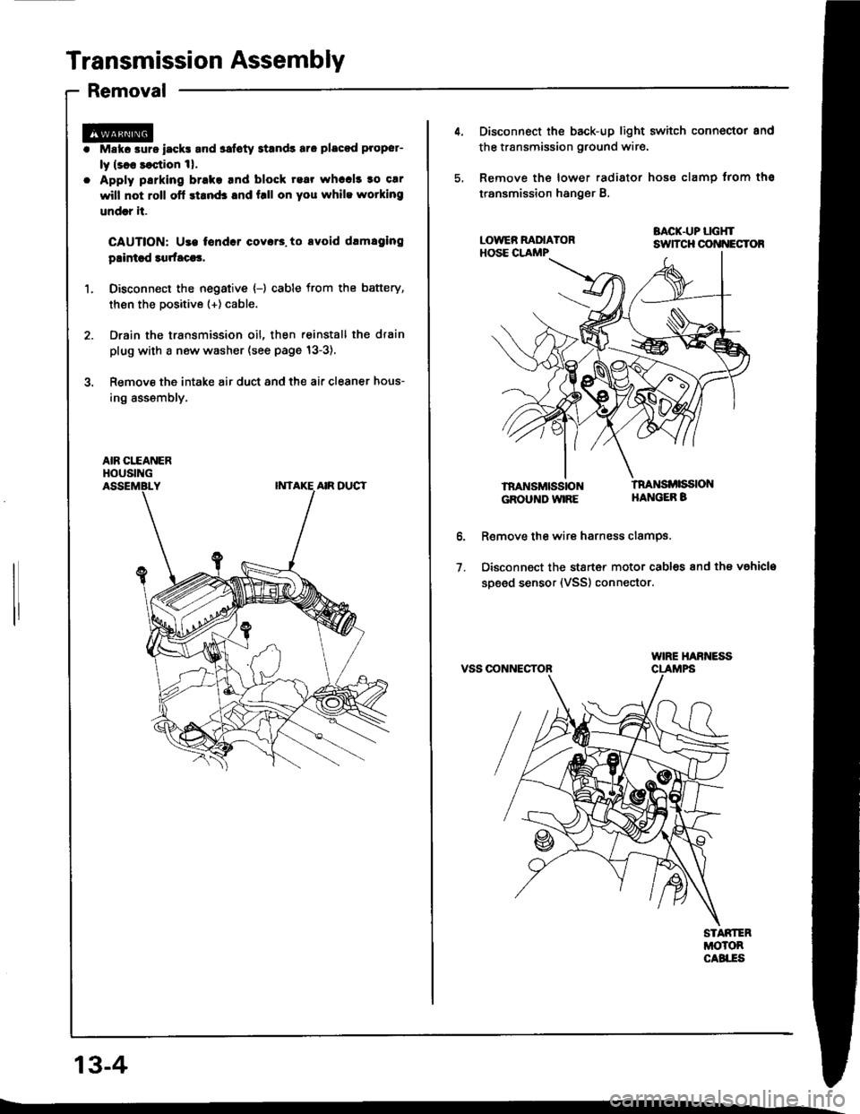
Transmission Assembly
Removal
Mskc aurs iack! and safoty Etands aro placod proper-
ly lsl8 saqtion 1|.
Apply parking brake tnd block rear whccl! to car
will not roll ofl stand3 and f.ll on you while wotking
undrr it.
CAUTION: Use tondcr coyar3. to avoid drmlging
plintsd 3qrfaca3,
Disconn€ct the negative {-) cable from the battery,
then the positive (+) cable.
Drain the transmission oil, then reinstall the drain
plug with a new washer (see page 13-3),
Remove the intake air duct and the air cleaner hous-
ing assembly,
AIR CITANERHOUSING
13-4
4. Disconnect the back-up light switch connoctor and
the transmission ground wir€.
5, Remove the lower radiator hose clamp trom ths
transmission hanger B.
BACK.UP LGHTsuTcH cot{t{EcToR
lnaNsMttistoNGROUND WIRE
tnaNsi ssloNHANGEB B
o.
1.
R€move the wire harness clamPs.
Disconnect the stsrt€r motor cables and the vahicla
soeed sensor (VSS) connector.
VSS OONNECTOR
Page 367 of 1413
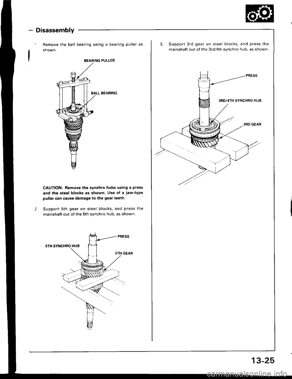
- Disassembly
Remove the ball bearing using a bearing puller as
BEARING PULLER
BALL B€ARING
CAUTION: Remove the synchro hubs using a press
and the steel blocks .s shown. Use of a jaw-type
puller can cau3e damags to the gear teeth.
Support 5th gear on steel blocks, and press the
mainshaft out of the 5th synchro hub, as shown.
3.Support 3rd gear on steel blocks, and press the
mainshaft out of the 3rd/4th synchro hub, as shown.
13-25
Page 369 of 1413
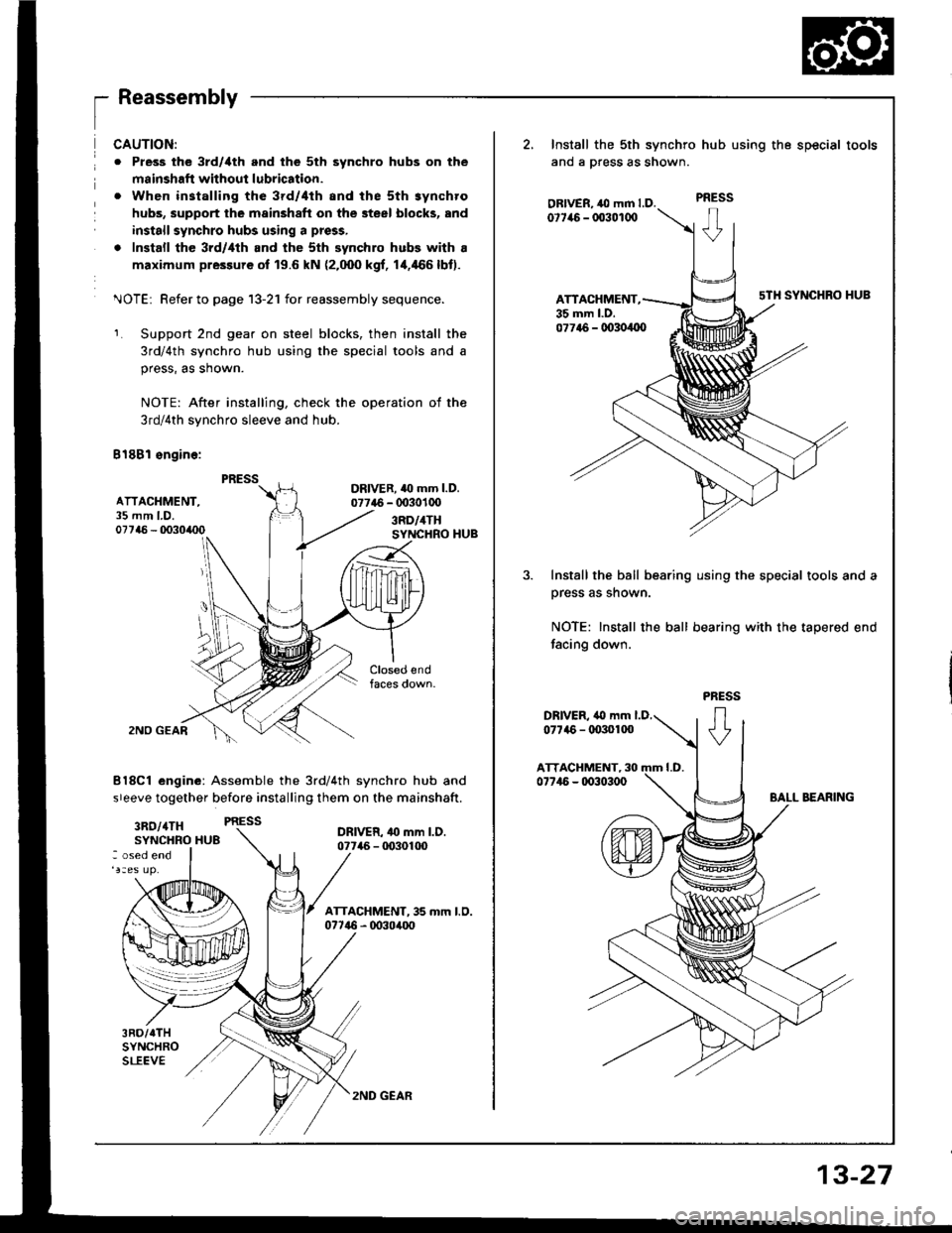
1_
ReassemblV
ATTACHMENT,35 mm LD.07746 - 0o30/rc0
CAUTION:
o Pless the 3rd/ilth and the 5th synchro hubs on the
msinshafi without lubrication.
. When installing the 3rd/4th and the sth synchro
hubs, support the mainshaft on the steel blocks, and
install synchro hubs using a press,
. Install the 3rd/,lth and the sth synchro hubs with a
maximum pressure of 19.6 kN (2.000 kgf, 1+466lbt).
^JOTEi Refer to page 13-21 for reassembly sequence.
Support 2nd gear on steel blocks, then install the
3rd/4th synchro hub using the special tools and a
press, as shown.
NOTE: After installing, check the operation of the
3rd/4th synchro sleeve and hub.
B18Bl sngine:
DRIVER. 40 mm l.D.07746 - 0030100
3RD/4THSYNCHRO HUB
2NO GEAR
8l8Cl engine: Assemble the 3rd/4th synchro hub and
sreeve together before installing them on the mainshaft.
3RO/4TH PRESS
SYNCHRO HU8DRIVER- 4o mm l.D.07746 - tD30100: osed end
3RD/TTHSYNCHROSLEEVE
2, Install the sth synchro
ano a press as snown.
OBIVER, ,O mm LD.0t7it6 - 003010O
ATTACHMENT,35 mm l.D.
hub using the special tools
PRESS
sTH SYNCHRO HUB
077t6 - 00304{x)
Install the ball bearing using the special tools and a
prsss as shown.
NOTE: Install the ball bearing with the tapered end
facing down.
2ND GEAR
13-27
Page 372 of 1413

Countershaft Assembly
Disassembly
13-30
't.Securely clamp the countershaft assembly in a
bench vise with wood blocks.
Raise the locknut tab from the groove in the coun-
tershaft, then remove the locknut and the spring
washer.
4,Remove the bearing outer .ace, then remove the
needle bearing using a bearing puller as shown.
2.
BEARING PULLER
BEARING
Remove the ball bearing using a bearing puller as
shown.
CAUTION: Romove the gclrs using a pross and tho
steol blocks rs shown. U3a of a l.w.typo pullor can
cau36 damagg to tho gsar iocth.
Support 4th gear on steel blocks. and press the
countershaft out of sth and 4th gears, as shown.
PULlTR
\-Y
Page 374 of 1413
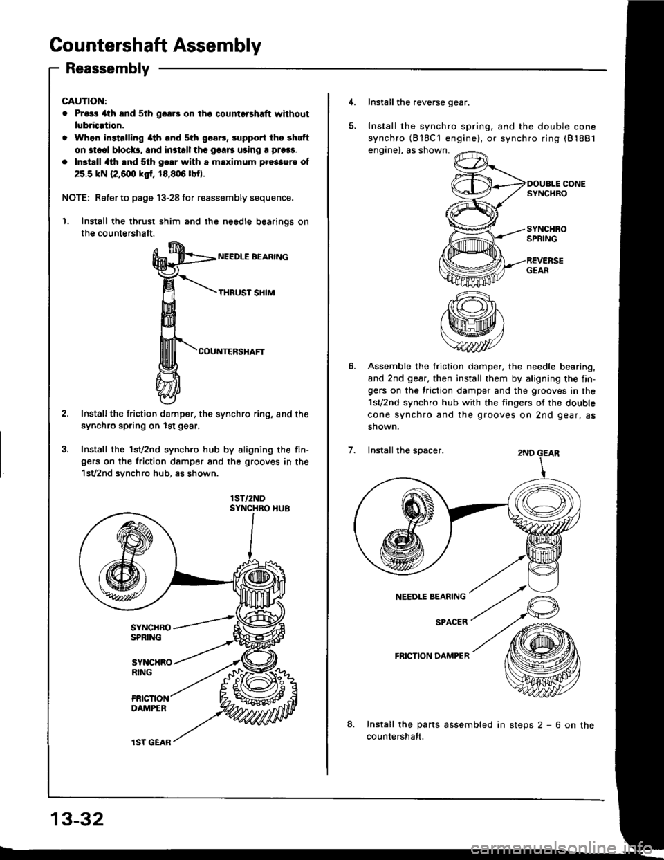
Countershaft Assembly
Reassembly
GAUTION:
. Pr93r 4th and 5th goar3 on the qountorshrft without
lubricrtion.
. Whon in3talling 4th and sth goa6, srpport the shaft
on st..l block3, 8nd in3tall thc 9.116 uring a prors.
. Inst.ll 4th lnd 5th gcar with a maximum pro33ur€ of
25.5 kN (2,6@ ksr. 18,806 lbo.
NOTE: Refer to page 13-28 for reassembly sequence.
Install the thrust shim and the needle bearinos on
the countershaft.
NEEDLE BEARING
THRUST SHIM
COUNTERSHAFT
Installthe friction damper. the synchro ring, and the
synchro spring on lst gear,
Install the lsv2nd synchro hub by aligning the fin-gers on the friction damper and the grooves in the'lsV2nd synchro hub, as shown.
1ST/2ND
13-32
lST GEAR
4. Install the reverse gear.
Install the synchro spring, and the double cone
synchro (818C'l engine), or synchro ring (81881
engine), as shown.
SYNCHROSPRING
REVERSEGEAfi
Assemble the friction damper, the needle bearing,
and 2nd gear, then install them by aligning the fin-gers on the friction damper and the grooves in the
1sv2nd synchro hub with the fingers of the double
cone synchro and the grooves on 2nd gear, as
shown.
2ND GEAR
NEEDLE BEARING
SPACER
FRICTION DAMPER
8.Install the parts assembled in steps 2 - 6 on the
countershaft.
Install the spacer.
Page 375 of 1413
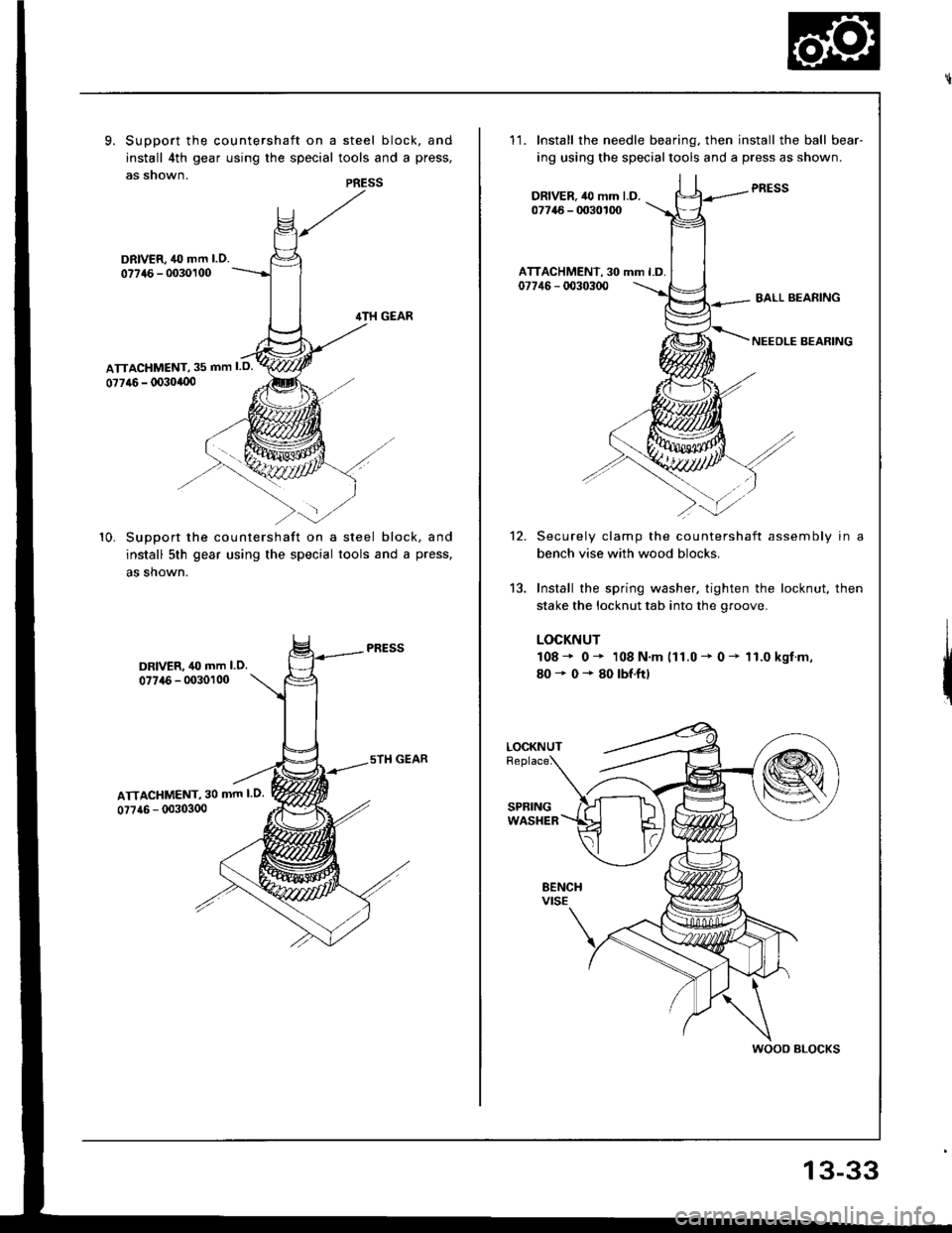
9. Support the countershaft on a steel block, and
install 4th gear using the special tools and a press,
as snown.PRESS
DRIVER, 40 mm l.O.
077{6 - 0030100
10. SuDDort the countershaft on a steel block, and
install 5th gear using the special tools and a press,
as shown.
DRIVER, 40 mm l.O.07746 - 0030100
ATTACHMENT, 30 mm l.O.
0?7a6 - (X)303(x)
11.Install the needle bearing. then install the ball bear-
ing using the specialtools and a press as shown.
PRESSDRIVER.,l0 mm l.D.07746 - 0030100
ATTACHMENT, 30 mm l.D.07746 - d)30300BALL BEARING
NEEDLE BEARING
12.
13.
Securely clamp the countershaft assembly in a
bench vise with wood blocks.
Install the spring washer. tighten the locknut, then
stake the locknut tab into the groove.
LOCKNUT
108* 0* 108 N.m (11.0 - 0 - 11.0 kgf.m,
80+0*80lbf.ftl
LOCKNUT
wooo BLocKs
13-33