fuse box HONDA INTEGRA 1994 4.G Repair Manual
[x] Cancel search | Manufacturer: HONDA, Model Year: 1994, Model line: INTEGRA, Model: HONDA INTEGRA 1994 4.GPages: 1413, PDF Size: 37.94 MB
Page 1157 of 1413
![HONDA INTEGRA 1994 4.G Repair Manual Under-hood ABS Fuse/Relay Box
Wire Color
C9O3 ITo ABS pump molor rolayl
C9O1 [To main wiro ham6$ (C212]l
Componont (s) or Circuit (sl Protectsd
T5 [To undo]-hood ABS fuso/rolay box cabl.l
C9O2 [To moi HONDA INTEGRA 1994 4.G Repair Manual Under-hood ABS Fuse/Relay Box
Wire Color
C9O3 ITo ABS pump molor rolayl
C9O1 [To main wiro ham6$ (C212]l
Componont (s) or Circuit (sl Protectsd
T5 [To undo]-hood ABS fuso/rolay box cabl.l
C9O2 [To moi](/img/13/6067/w960_6067-1156.png)
Under-hood ABS Fuse/Relay Box
Wire Color
C9O3 ITo ABS pump molor rolayl
C9O1 [To main wiro ham6$ (C212]l
Componont (s) or Circuit (sl Protectsd
T5 [To undo]-hood ABS fuso/rolay box cabl.l
C9O2 [To moin wiro hs1n6ss (C213]l
ABS 8120AWHT/GRNRight/left ABS front solenoids
ABS 8215 AWHTABS control unit, ABS rear solenoid
ABS MOTOR40AABS pump motor relay, ABS unit (10 A) fuse
ABS UNIT10 ABRN/YELABS control unit
23-51
Page 1158 of 1413
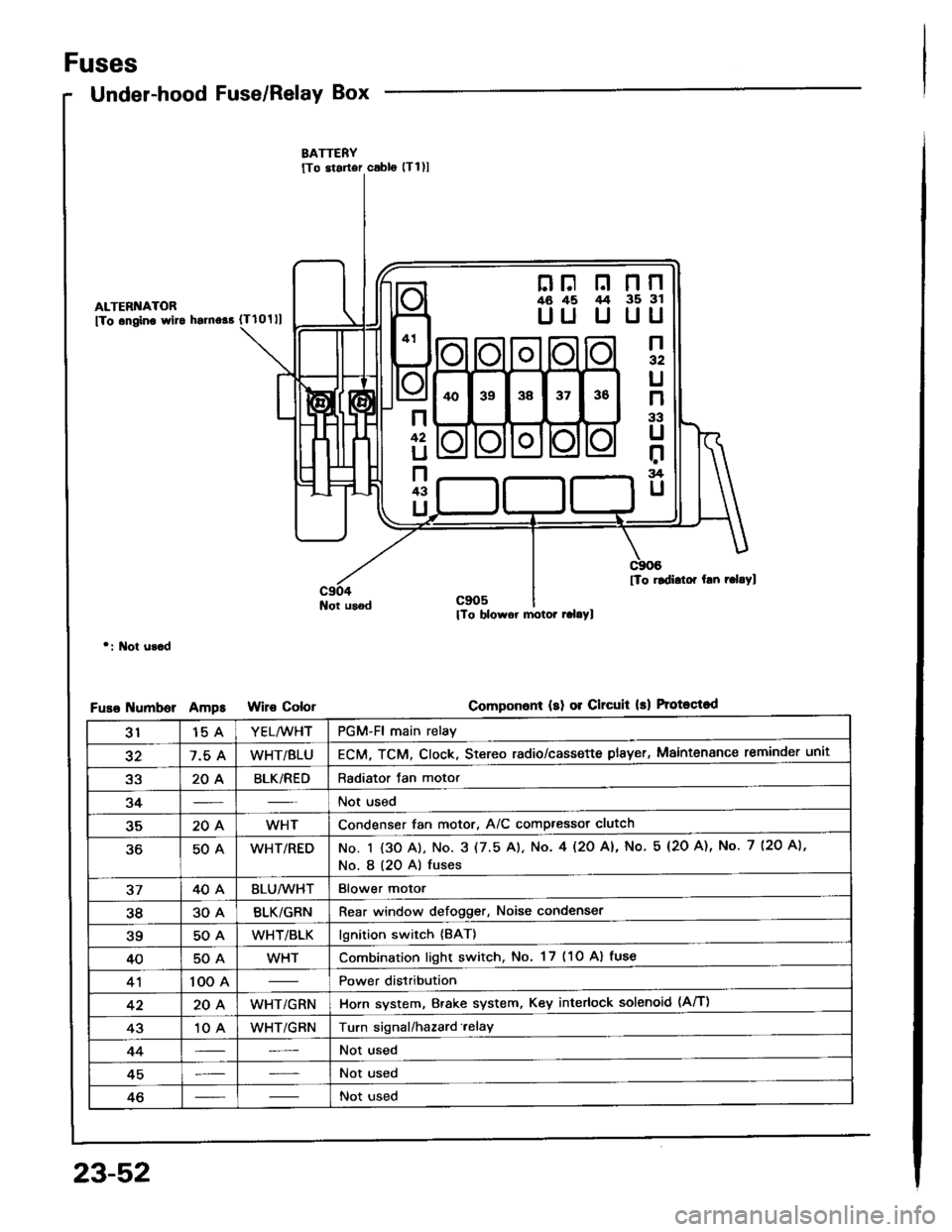
Fuses
Under-hood Fuse/Relay Box
ALTERI{ATOR
fTo .ngino wlto hsrno$ {Tlolll
Not usod
r: l\lot u3.d
umborAmpsColor
nF n nn46 45 /t4 35 3l
UU U UU
n32
U
n
33
U
r:rg
U
n
42
U
n43
U
[To rldidor hn r.l.Yl
Componon! (sl 01 Clrcuit 13) Protoqtod
3115 AYEL/WHTPGM-Fl main relay
327.5 AWHT/BLUECM, TCM. Clock, Stereo radio/cassette plsyer, Maintenance reminder unit
a2204BLK/REDRadiator Jan motor
34Not used
35204WHTCondenser fan motor, A/C compressor clutch
50AWHT/REDNo. I {3O A), No. 3 (7.5 A). No. 4l2O Al, No 5 (2O A), No. 7 (2O A),
No. I (20 A) fuses
3740ABLU/lVHTBlower motor
3830ABLK/GRNRear window defogger, Noise condenser
?q50AWHT/BLKlgnition switch {BAT}
4050AWHTCombination light switch, No. 17 (1O Al fuse
41100 APower distribution
4220AWHT/GRNHorn system, Brake system, Key interlock solenoid (Aff)
4310 AWHT/GRNTurn signal/hazard.elay
44Not used
45Not used
46Not used
23-52
Page 1159 of 1413
![HONDA INTEGRA 1994 4.G Repair Manual NOTE; View from the backside of the under-hood fuse/relav box
c907lTo m.ln wiro h.mo$ (C214)l
[To msin wlro hEmoss lc215l]
c911lTo ftain wiro hamers (C218)l: USA
lTo mlln wlr. hlmct. (C216li
lTo mrin HONDA INTEGRA 1994 4.G Repair Manual NOTE; View from the backside of the under-hood fuse/relav box
c907lTo m.ln wiro h.mo$ (C214)l
[To msin wlro hEmoss lc215l]
c911lTo ftain wiro hamers (C218)l: USA
lTo mlln wlr. hlmct. (C216li
lTo mrin](/img/13/6067/w960_6067-1158.png)
NOTE; View from the backside of the under-hood fuse/relav box
c907lTo m.ln wiro h.mo$ (C214)l
[To msin wlro hEmoss lc215l]
c911lTo ftain wiro hamers (C218)l: USA
lTo mlln wlr. hlmct. (C216li
lTo mrin wiro hameq lC217ll
23-53
Page 1161 of 1413
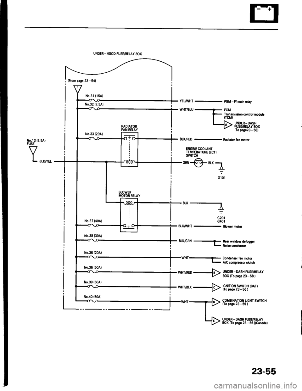
{From p.So 23 - 541
No.l317.5AlFUSE
VL swyel
UNDER _HOOD FUSE/NEUY 8OX
n^OIATORFAN REI-AY
BTOWERMOTOR RETAY
YELJWHT - PGM -R mlin |rhv
TrdEmirConco rolrl|oduLfrcMt
UI{DEF -OASHFUSSRELAY BOXtTo p!9c23 - 581
8LK/RED - Radi.tor fln molor
ENGII{E COOTAMITEMPEMTURE IECT)swtTcH
*@"r;1
o iot
'"----
G20tG40t8LU/WHT - 8bw.r motor
8tX/GRtl -f R!!r window d,.to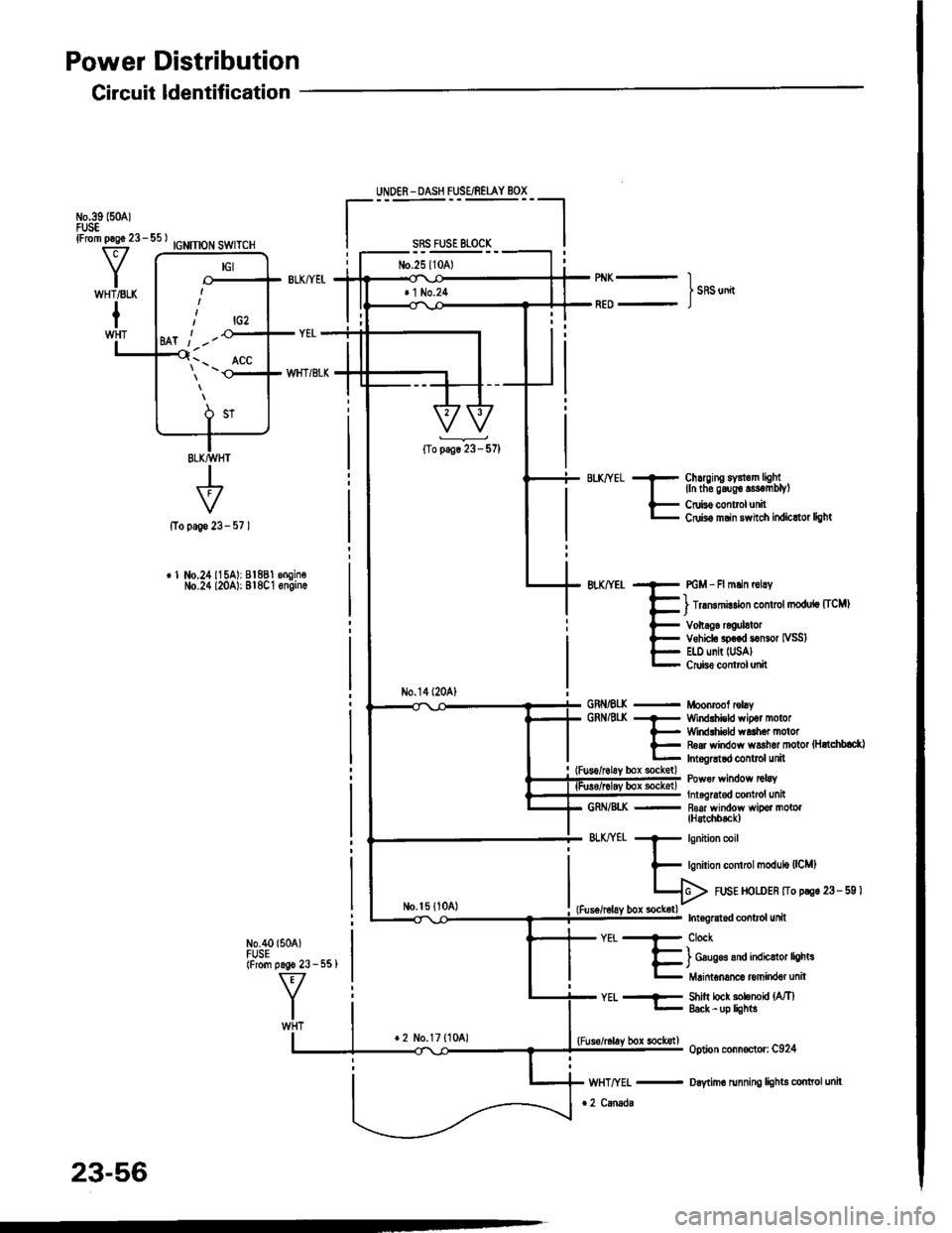
Power Distribution
Circuit ldentification
IGNITION SWITCH
+page 23-
r 1 No.24115A): 81881 engin€No.24 l20A): Bl8C1 6ngin.
N0.40 {504)FUSE(From pago 23 - 551
UNDER - DASH FUSE/REIAY BOX
sRs FusE 81-0cK
No.25l10Al
No.14l20A)
No.l5 {1041
Chuging sY3l.m lightlln tho g6ug€ s3€mblyl
Cruis€ controlunitCdis6 msin 3whch itdicttor light
PGM - Fl mlin r6lry
) lrrmmirdon control modulo [ICM)
Vohag6 rcoulatorVehiclo sp.€d somor IVSS)E|.l) unit IUSA)Crube conttol unit
Moonrcof rclayWind.hicld wipot motorWirdlhi€ld waah6. motorR6ar window ws3hor motot {HrtchblctlInt.gGtod control unit
Power wirdow tclaY
Int6lrat€d contrcl unit- R6af window wipor motol(H3tchbtck)
571
GRNiEI(GRNAt(
GRN/8I..K
BLKffEt
-EiT"h#,H#J:r"
Shitt lock solenoU {MlEack -up lights
option conn€ctor: C924
Daytimo running lights conttol unit
YEt..--
lrcz
Ml t -'-
\'- _ ^ACC
23-56
*2 No.17 {1041bor sockstl
Page 1163 of 1413
IGNITION SWTCH ISTIlFrom p.!€ 23 - 561
f7
I.---F-------lI-lSTARTFPi Bffi,!'HT 6u?'ili,iY i| -' r r l clurcr It-11iPt ;rui8rr H inl-rhicicxswrcr 1,,,,,,Itill-+{ .'.i o-F BIK/RED --.5 BLX/!\,HT - st.der sotenoid il-l I r
BLK/REO
fr
r---
uxrivn Sr$!gfr*,r.,
L€-eumoBLKMHT - Starlsr solenoki
-------J
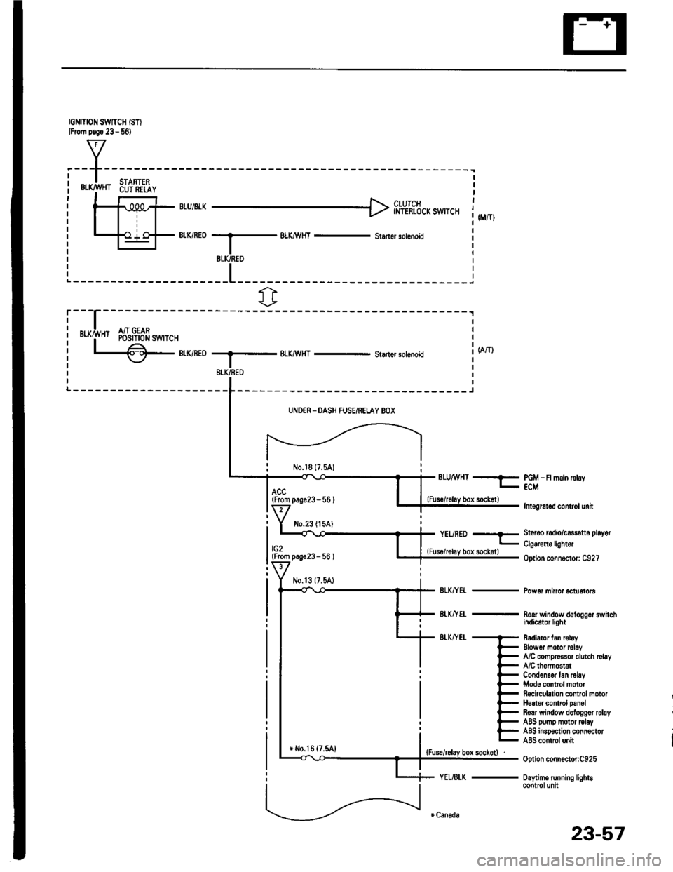
UNDER -DASH FUSEiRELAY BOX
No.l817.5A)ELUMHT --?- PGM _ Ft msin rctay- ECM
lnt€gretod control unit
St6r6o radio/c$r€tt6 playot
Cig€rone lightor
Option connoctor: C927
Pow6r minor *tuetols
noar wandow dologgor switchindicrtor light
R6dietor fan robyElowor motor rclayfuC compr$sor clutch rsl6yA/C lhomGtstCond6ns& tan ml6yMod6 control motorRocicubtion control motorH6at€r control panolRear window deloggor relayABS pomp motor tolayABS insp€ction connoctorABS contrcl unit
Option connoctor:C925
Daytime running lightscontrolunit
(From pag623-56 )
No.23ll5AlYEURED --E
lG2lFrom p.!623- 56 ){Fus€/relay box sockotl
+ l,lo,16 {7.5A1
23-57
Page 1164 of 1413
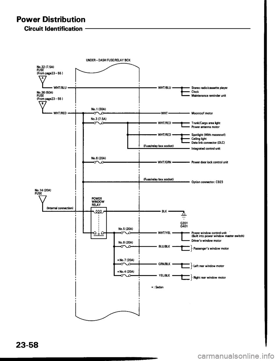
Power Distribution
Circuit ldentification
No,14l20 lFUSE
{lntomal connaclionl
UNOER - OASH FUSE/REI-AY BOX
WHT/RED - TrunUcergo .rur lght- Fbwer .nr.nn! moror
WHT/REof
Ebox sockstl
WHT/GRN -
*-
G20tG40l
Spotlight (Wrt'h moonmollC.ilin! lightDrl! link conn ctor lDLCl
Irtogrltad control unit
Pow6r door locl control unit
option connoclor: C923
WHTIYEL * Powor window conttolunrt| {&ih into Dowor window marloi rwhchll- p,i""1" *;n6o* n o1o,
BLU/4X +ll_ | l,lssrng6r's wndow motor
GRN/BLX -
YEUE|-K -
) Left rerr window moror
) ftenr oar winoow motor
r: Sedln
23-58
Page 1172 of 1413
Battery
a Battory tluid (6lectrolyt€l contains sulturic acid. lt may cauaa aevere burns iI it gots on your skin or in youl oyos.
Woar protoctivo clothing and I fac€ shield,- ll aloctrolyt6 gots on youl skin or clothos, rimo it off with wator immediately,- lf eloclrolyto g6ts in your oyos, tlush it out by splashing wat6r in youl eyes for at least 15 minutes; call a physiclan
immediately,
a A battery gives off hydrogon gas, lf ignit6d. tha hydrogsn will orploda and could crack tho baflory cas6 and splattor
acid on you. Koep spa*s. flames, and cigarottos away from the baftery.
a Overcharging will raiso ths tempelature ot th€ electrolyte. This may force electrolyte to splay out of the battery venta.
Follow lhe chargor manutacturer's instluctions and chargo tho battory at a prop61 rate.
NOTE: The original radio has a coded theft protection circuit. lt service to the car requires any of the lollowing, be sure
to get the customer's code number before- disconnecting the battery.- removing No. 32 (7.5 Al fuse from the under-hood fuse/relay box- removing the radio,
After service, reconnect power to the radio and turn it on. When the word "CODE" is displayed, enter the customer's
s-digir code to restore radio operation,
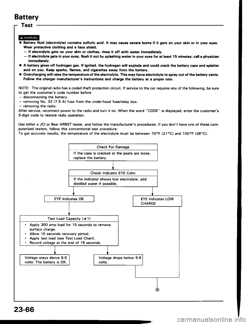
Use either a JCI or Bear ARBST tester, and follow the manufacturer's procedures. It you don'r have one of these com-puterized testers, follow this conventional test procedure:
To get accurate results, the temperature ot the electrolyte must be between TOoF l21ool and IOOoF {38oCl.
lf the case is cracked or the posts are loose,
replace the battery.
lf the indicator shows low electrolvte, add
distilled water it oossible.
Test Load Cspacity (# 1)
. Apply 3OO amp losd fo. 15 seconds to remove
surJace charge.. Allow 15 seconds recovery period.. Apply test load (see Test Load Chartl.. Record voltage at the end of 15 seconds.
Voltage stays above 9.6
volts: The batterv is OK.
23-66
Page 1176 of 1413
lgnition Switch
CAUTION:
a All SRS electdcal wiring harnessss aro covotod whh
yollow insulation.
a Botore disconnocting any part ot th6 SRS wiro har-
n6ss. connoct tha shon connoctor(t).
a Replac€ tho ontiro affected SRS hames! asllmbly It
it has an op6n circuit 01 damagod widng.
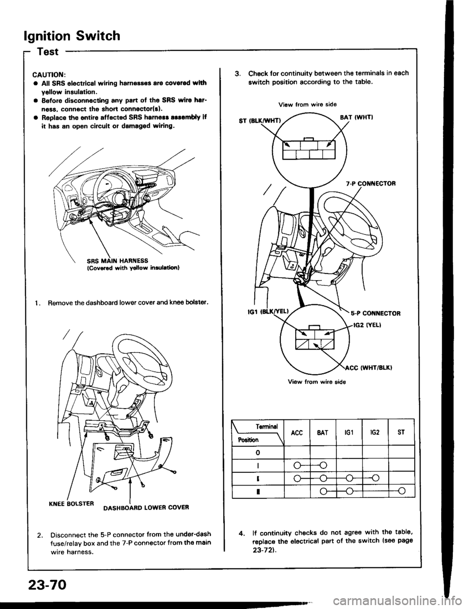
1. Remove the dashboard lower cover and knee bolster.
KNEE BOLSTERDASHBOARD LOWER COVER
Disconnect the 5-P connector flom the undsr-dash
fuse/relav box and the 7-P connector from the main
wire harness.
23-70
SRS MAIN HARI{ESS(Cov6red with Yollow inrulltiori)
J.Chsck tor continuity b€tween the terminals in each
switch position according to the table.
4. lf continuity checks do not agre€ with the tabl6,
reolace the €lectrical part of the switch lsee page
23-72t.
Terninal
P6itionBATtG1ST
--o
o-
I
Page 1177 of 1413
Electrical Switch Replacement
a All SRS €lectric8l wiring hamosses ar€ covorsd withyellow insulation,
a Befora disconnecting any pan of tho SRS wilo har-neas. connect the short connoctor(sl.a R6place the entire attect6d SFS harness assombly ifit has an opon circuit 01 damaged wiling.
NOTE: The original radio has a coded theft protection
circuit, Be sure to get the customer's code number before- disconnecting the battery.- removing the No. 32 (7.5 Al fuse from the under-hoodluse/relay box.- removang the radio.
After service, reconnect power to the radio and turn iton. When the word "CODE" is displayed, enter the cus-tomer's 5-digit code to restore radio ope.ation.
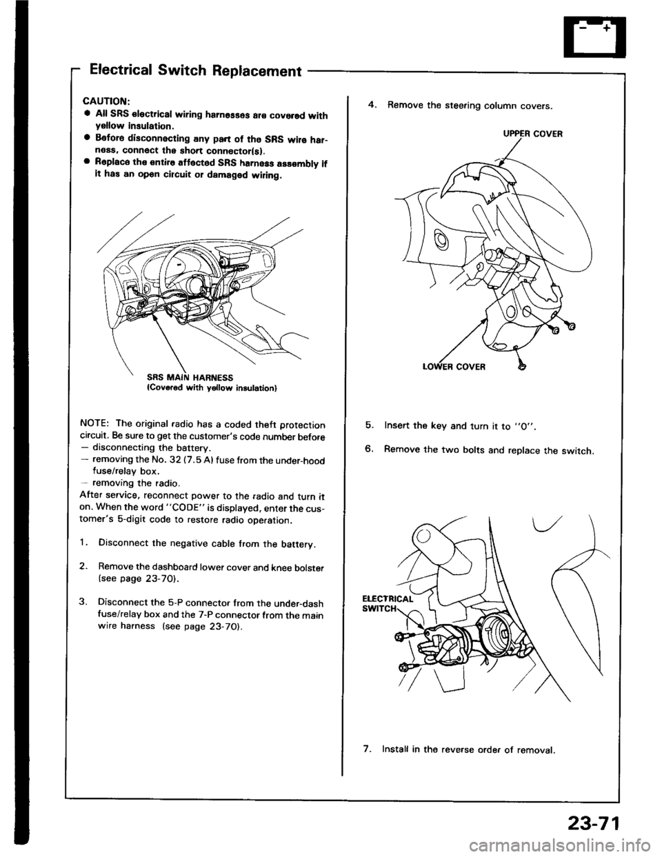
1. Disconnect the negative cable from the batery.
2. Remove the dashboard lower cover and knee bolster
{see page 23-70).
3. Disconnect the 5-P connector from the under-dashfuse/relay box and the 7-P connector from the mainwire harness (see page 23-70).
E
4. Remove the steering column covers.
Insert the key and turn it to ,,O',.
Remove the two bolts and replace the switch.
UPPER COVER
7. Install in the reve.se orde. of removat.
23-71