clutch HONDA INTEGRA 1994 4.G Repair Manual
[x] Cancel search | Manufacturer: HONDA, Model Year: 1994, Model line: INTEGRA, Model: HONDA INTEGRA 1994 4.GPages: 1413, PDF Size: 37.94 MB
Page 409 of 1413
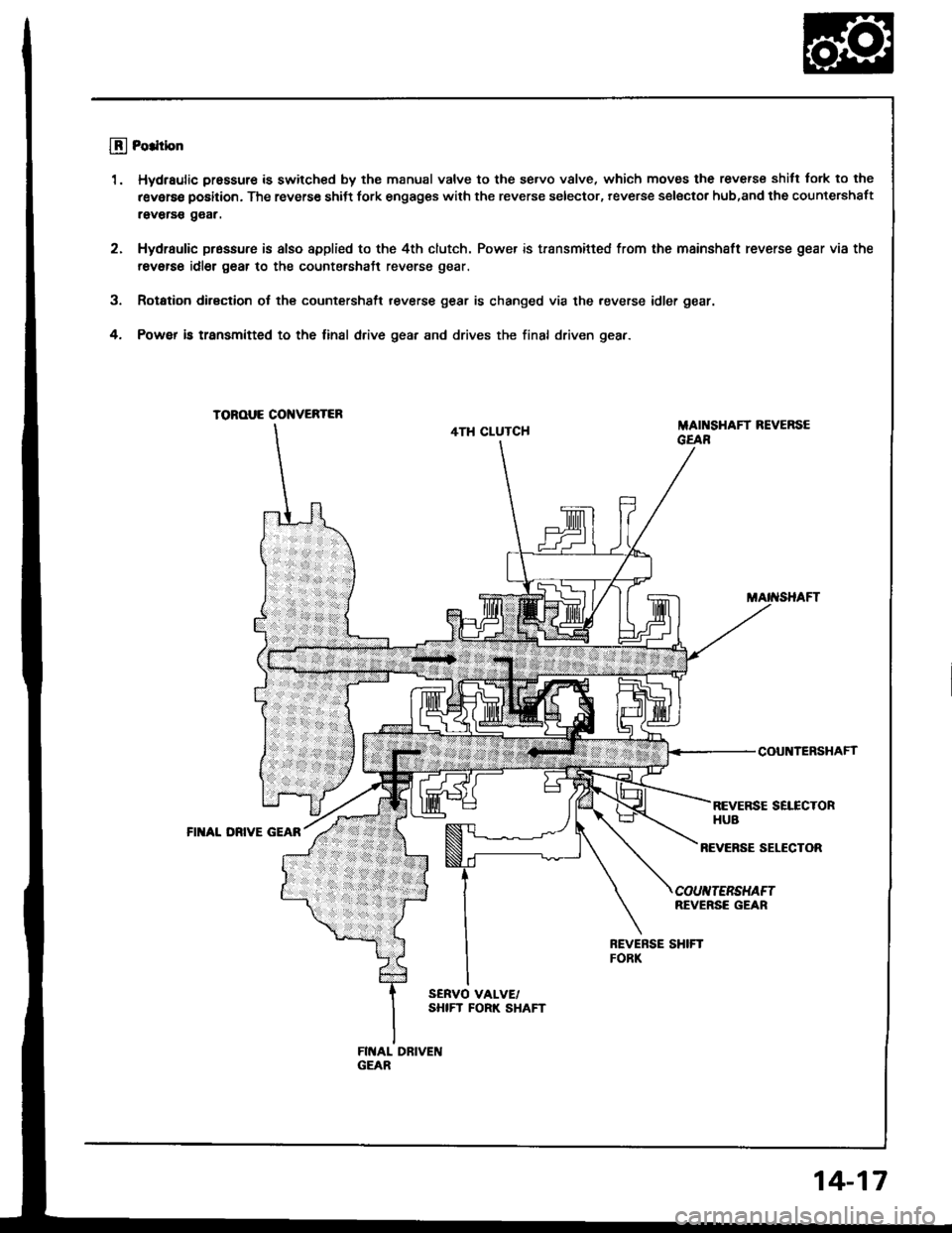
llj Po.ltbn
1. Hydraulic pressure is swilched by the manual valve to the se.vo v8lve, which moves the reverse shilt tork to the
r€verse position. The reverse shiJt fork engages with the reverse selector, reverse selsctor hub,and the countershaft
raverss g€ar.
2. Hydraulic pr6ssure is also appli€d to the 4th clutch. Power is transmifted from the mainshaft reverse gear via the
revetse idler g6ar to the countershaft reverse gear.
3. Rotation dirsction ol the countershsft reverse gear is changed via the .everse idler gear.
4. Powef b transmitted to the linal drive gear and drives the final driven gear.
TOROUE CONVEBTER
4TH CLUTCHMAI SHAFT REVERSEGEAR
COUNTERSHAFf
REVERSE SELECTORHUBFII{AL DRIVE GEAR
REVEFSE SELECTOR
COUIITERSHAFTREVERSE GEAR
14-17
Page 415 of 1413
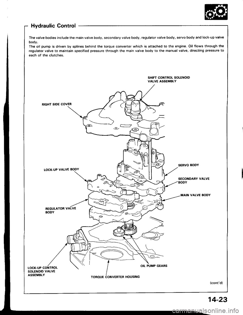
Hydraulic Control
The valve bodies include the main valve body, secondary valve body, regulator valve body, servo body and lock-up valve
body.
The oil pump is driven by splines behind the torque converter which is attached to the engine. Oil flows th.ough the
regulator valve to maintain specified pressure through the main valve body to the manual valve, directing pressure to
each of the clutches,
SHIFT CONTROL SOLEIIOIDVALVE ASSEMBLY
RTGHT SIDE COVER
LOCK.UP VALVE BODY
VALVE BODY
REGULATOR VBODY
SOLENOID VALVEASSEMBLY
4<.__i: )o.-
OIL PUMP GEARS
14-23
Page 419 of 1413
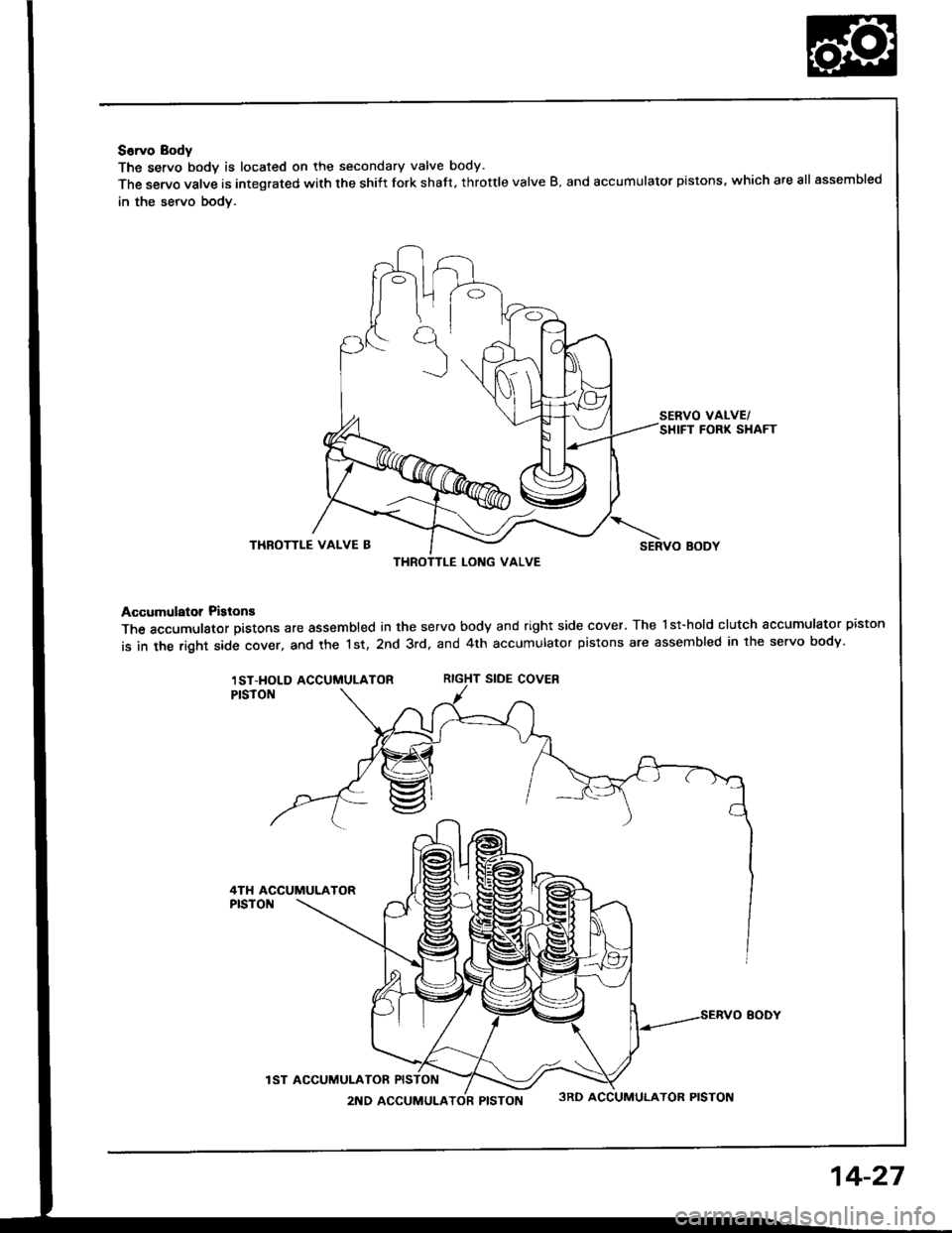
S6rvo Body
The servo bodv is located on the secondary valve body.
The servo valve is integrated with the shiit fork shatt, throttle valve B. and accumulator pistons, which are all assembled
in the servo bodv.
SERVO VALVE/SHIFT FORK SHAFT
THROTTLE VALVE BSERVO BODY
Accumulator Pislons
The accumulator pistons are assembled in the servo body and right side cover. The l st-hold clutch accumulator piston
is in the right side cover, and the 1st, 2nd 3rd, and 4th accumulator pistons are assembled in lhe servo body.
RIGHT SIDE COVER
THROTTLE LONG VALVE
1ST-HOLD ACCUMULATOR
4TH ACCUMULATOR
IST ACCUMUI-ATOR
2ND ACCUMULATOR PISTON3RD ACCUMULATOR PISTON
14-27
Page 420 of 1413
![HONDA INTEGRA 1994 4.G Repair Manual Description
Genelal Chart ol Hydraulic Pressure
Hydraulic Flow
. Regulator Valve
. Manual Valve
. Modulator Valve
. 1-2 Shilt Valve l. 2-3 Shitt Valve. 3 4 Shift Vlave ]
. Throttle Valve B
Oil Pump - HONDA INTEGRA 1994 4.G Repair Manual Description
Genelal Chart ol Hydraulic Pressure
Hydraulic Flow
. Regulator Valve
. Manual Valve
. Modulator Valve
. 1-2 Shilt Valve l. 2-3 Shitt Valve. 3 4 Shift Vlave ]
. Throttle Valve B
Oil Pump -](/img/13/6067/w960_6067-419.png)
Description
Genelal Chart ol Hydraulic Pressure
Hydraulic Flow
. Regulator Valve
. Manual Valve
. Modulator Valve
. 1-2 Shilt Valve l. 2-3 Shitt Valve. 3 4 Shift Vlave ]
. Throttle Valve B
Oil Pump - Regulator Valve -
Distribution ot Hydraulic Pressure
Line Pressure
Torque Converter Pressure
Lubrication Pressure
-,.Ltne rressure
] Torque Converter Pressure
L Lubrication Pressure
To Select Line Pressure
Modulator Pressure
Clutch Pressure
Throttle B Pressure
NO.DESCRIPTION OF PRESSURENO.DESCRIPTION OF PRESSURENO.DESCRIPTION OF PRESSURE
ILIN E6CMODULATOR
ITOCK-UP CONTROL SOLENOID VATVE AI55THROTTLE B
2LIN E6DMODULATOR(IOCX.UP CONTROT SOTENOID VALVE B)56THROTTLE B
3LIN E9LIN E57THROTTLE B
3'LINE10l ST CLUTCH58THROTTLE B
3"LINE1ST-HOLD CLUTCH90TOROUE CONVERTER
4LIN EIt)l ST.HOLD CLUTCH91TOROUE CONVERTER
LIN E18LINE92TOROUE CONVERTER
5LIN E202ND CLUTCH93OIL COOLER
5'LIN E212ND CLUTCH94TOROUE CONVERTER
5"LIN E25LIN E95LUBRICATION
6MODULATOR303RD CLUTCH96TOROUE CONVERTER
6'�MODULATOR313RD CLUTCH97TOROUE CONVERTER
6AMODULATOR(SHIFT CONTROL SOTENOID VALVE A404TH CLUTCH99SUCTION
6BMODULATOR(SHIFT CONTROL SOLENOID VALVE B414TH CLUTCHBLEED
14-28
Page 421 of 1413
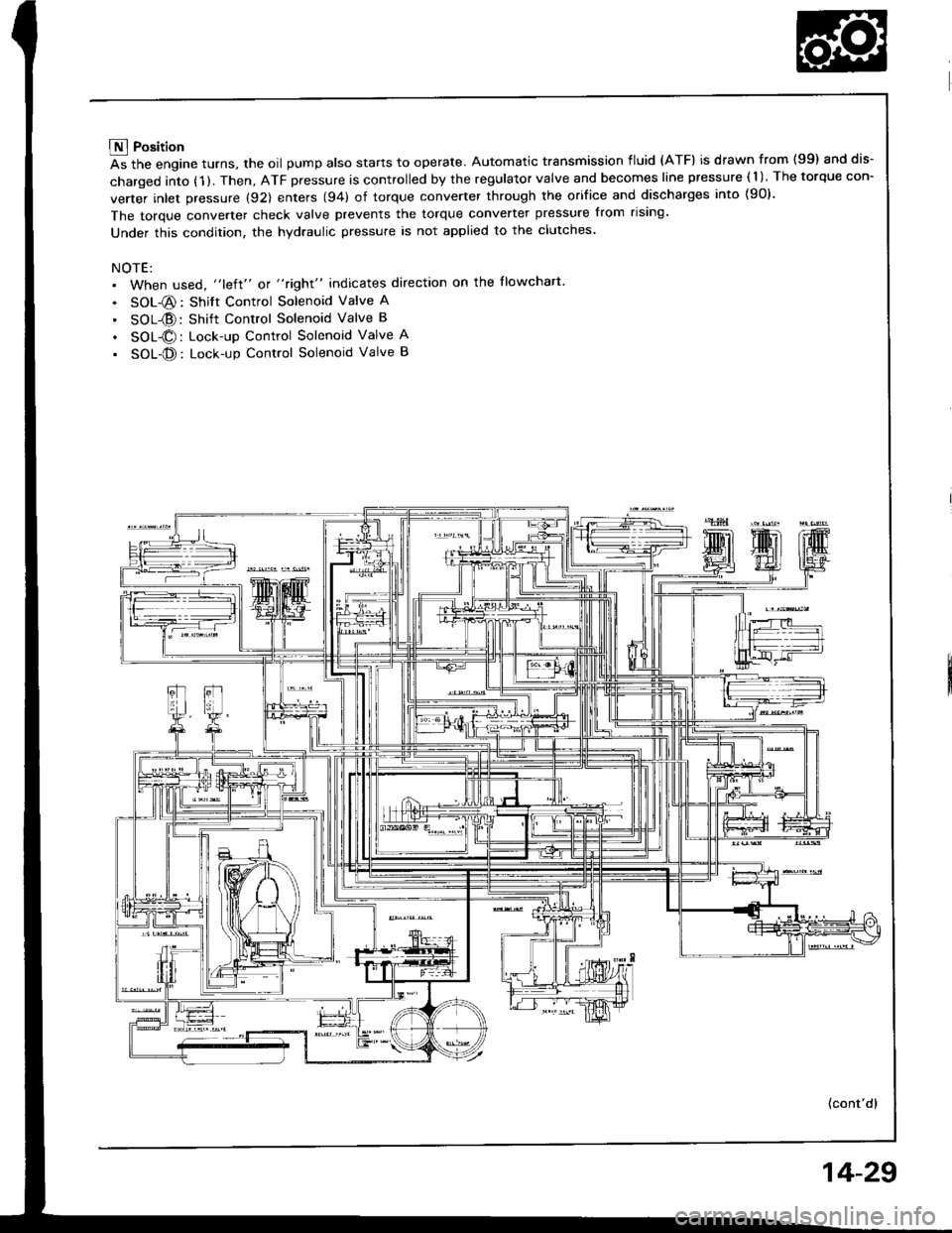
E Position
As the engine turns, the oil pump also starts to operate. Automatic transmission fluid (ATF) is drawn from (99) and dis-
charged into (1 ). Then, ATF pressure is controlled by the regulator valve and becomes line pressure ( 1 ). The torque con-
verter inlet pressure (92) enters (94) of torque converter through the orifice and discharges into {90}.
The torque converter check valve prevents the torque converter pressure from rising'
Under this condition, the hydraulic pressure is not applied to the clutches.
NOTE:. When used, "left" or "right" indicates direction on the llowchart
. SOL-@: Shift Control Solenoid Valve A
' SOL{D:Shift Control Solenoid Valve B
. SOL@: Lock-up Control Solenoid Valve A
. SOL-@: Lock-up Control Solenoid Valve B
(cont'd)
14-29
Page 422 of 1413
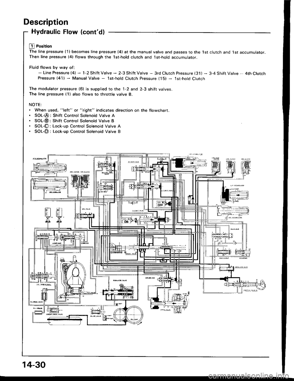
Description
Hydraulic Flow (cont'd)
L1l Position
The line pressure {1) becomes line pressure (4) at the manual valve and passes to the lst clutch and 1st accumulator.Then line pressure (41 flows through the 1st-hold clutch and lst-hold accumulator.
Fluid flows by way of:- Line Pressure {4} - 1-2 Shitt Valve * 2-3 Shitt Valve - 3rd Clutch Pressure {31) - 3-4 Shift Valve - 4th ClutchPressure (41) - Manual Valve - lst-hold Clutch Pressure {15) - 1st-hold Clutch
The modulator pressure (6) is supplied to the 1-2 and 2-3 shift valves.The line pressure (1) also flows to throttle valve B.
NOTE:. When used. "left" or "right" indicates direction on the flowchart.. SOL-@: Shift Control Solenoid Valve A. SOL@: Shift Control Solenoid Valve B. SOL-@: Lock-up Control Solenoid Valve A. SOL-@: Lock-up Control Solenoid Valve B
14-30
Page 423 of 1413
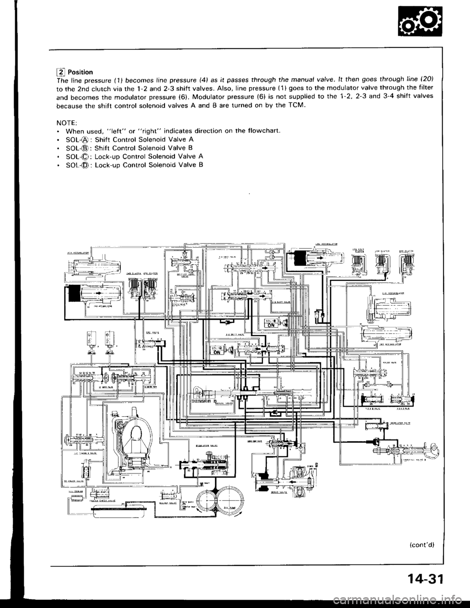
f4 Position
ihe line pressure (11 becomes line pressure (41 as it passes through the manual valve.lt then goes through line l2O)
to the 2nd clutch via the 1-2 and 2-3 shift valves. Also, line pressure (1 ) goes to the modulator valve through the filter
and becomes the modulator pressure (6). Modulator pressure (6) is not supplied to the 1-2, 2-3 and 3-4 shift valves
because the shitt control solenoid valves A and B are turned on by the TCM.
NOTE:. When used, "left" or "right" indicates direction on the flowchart
. SOL-@: Shift Control Solenoid Valve A
. SOL-@: Shilt Control Solenoid Valve B
. SOL-O: Lock-up Control Solenoid Valve A
. SOt -@ : Lock-up Control Solenoid Valve B
(cont'd)
14-31
Page 424 of 1413
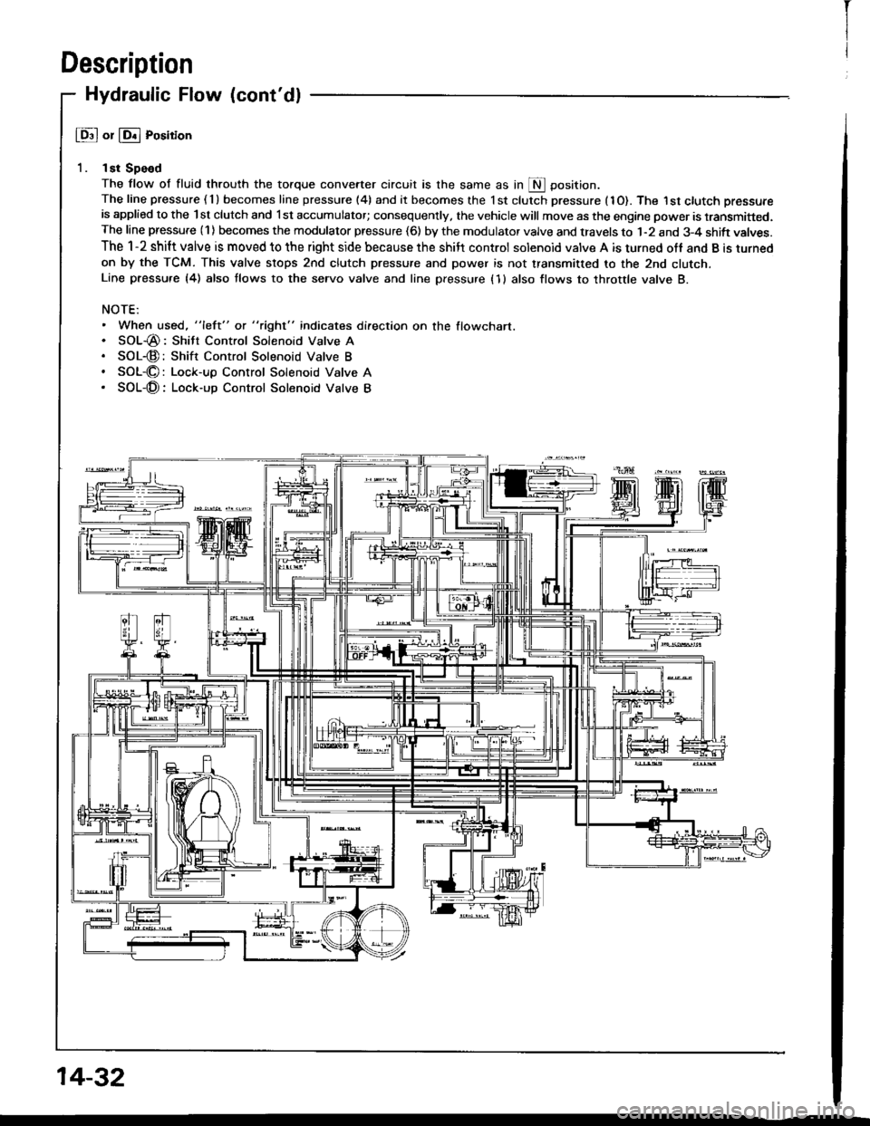
Description
Hydraulic Flow (cont'dl
@ or @ Position
1. lst Spe€d
The flow of fluid throuth the torque convener circuit is the same as in S Oosition.The line pressure ( 1 ) becomes line pressure (4) and it becomes the 1 st clutch pressure (1O). The I st ctutch pressure
is applied to the lst clutch and l st accumulator; consequently, the vehicle will move as the engine power is transmitted.The line pressure (1) becomes the modulator pressure (6) by the modulator valve and travels to 1-2 and 3-4 shift valves.
The 1-2 shift valve is moved to the right side because the shilt control solenoid valve A is turned off and B is turned
on by the TCM. This valve stops 2nd clutch pressure and power is not transmitted to the 2nd clutcn.Line pressu.e {4) also tlows to the seryo valve and line pressure (1 } also flows to throttle valve B.
NOTE:. When used, "left" or "right" indicates direction on the flowchart.. SOL-@: Shitt Control Solenoid Valve A. SOL-@:Shift Control Solenoid Valve B. SOL-O: Lock-up Control Solenoid Valve A. SOL-@: Lock-up Control Solenoid Valve B
14-32
I
Page 425 of 1413
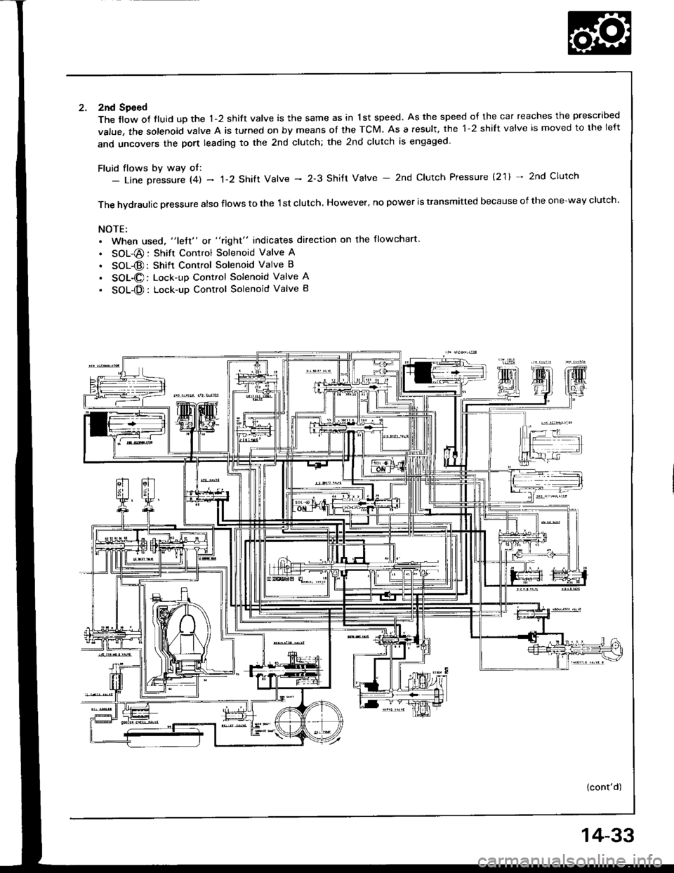
2nd Sgeed
The llow of fluid up the 1-2 shift valve is the same as in 1st speed. As the speed of the car reaches the prescribed
value, the solenoid valve A is tulned on by means ot the TCM. As a result, the 1-2 shift valve is moved to the left
and uncovers the port leading to the 2nd clutch; the 2nd clutch is engaged'
Fluid flows by way of:- Line Dressure l4l - 'l-2 Shift Valve - 2-3 Shitt Valve - 2nd Clutch Pressure (2'1) * 2nd Clutch
The hvdraulic pressure also flows to the 1st clutch, However, no power is transmitted because of the one-way clutch.
NOTE:. When used, "lett" or "right" indicates direction on the flowchart
. SOL-@: Shift Control Solenoid Valve A
. SOL@: Shift Control Solenoid Valve B
. SOL-@: Lock-up Control Solenoid Valve A
. SOL-@: Lock-up Control Solenoid Valve B
{cont'd)
14-33
Page 426 of 1413
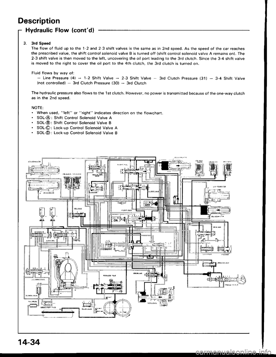
Description
Hydraulic Flow (cont'd)
3rd Speed
The tlow of fluid up to the 1-2 and 2 3 shift valves is the same as in 2nd speed. As the speed of the car reaches
the prescribed value, the shift control solenoid valve B is turned off {shilt control solenoid valve A remains on). The
2-3 shift valve is then moved to the left, uncovering the oil port leading to the 3rd clutch. Since the 3-4 shitt valve
is moved to the right to cover the oil port to the 4th clutch, the 3rd clutch is turned on.
Fluid tlows by way of:- Line pressure l4l - 1-2 shift valve - 23 Shift Valve * 3rd ctutch pressure (31) - 3-4 shift valve(not controlled) 3rd Clutch Pressure (3O) - 3rd Clutch
The hydraulic pressure also flows to the l st clutch. However, no power is transmitted because of the one-way clutchas in the 2nd speed.
NOTE:. When used, "lett" o( " tight" indicates direction on the flowcharl.. SOL-@: Shift Control Solenoid Valve A. SOL-@:Shift Control Solenoid Valve B. SOL-O: Lock-up Control Solenoid Valve A. SOL-@: Lock-up Control Solenoid Valve B
14-34