HONDA INTEGRA 1994 4.G Workshop Manual
INTEGRA 1994 4.G
HONDA
HONDA
https://www.carmanualsonline.info/img/13/6067/w960_6067-0.png
HONDA INTEGRA 1994 4.G Workshop Manual
Page 523 of 1413
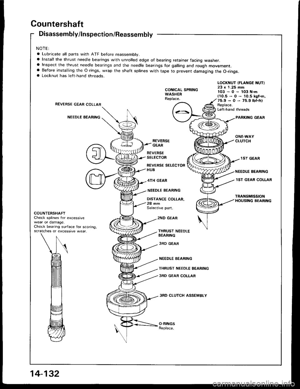
Countershaft
Disassembly/lnspection/Reassembly
NOTE:
a Lubricate all parts with ATF belore reassembly.a Install the thrust needle bearings with unrolled edge of bearing retainer facing washer.a Inspect the thrust needle bearings and the needle bearings tor galling and rough movement.a Before installing the O rings, wrap the shaft splines with tape to prevent damaging the O-rings.a Locknut has left-hand threads.
CONICAL SPRINGWASHERReplace.
LOCKNUT {FLANGE NUTI23 x 1.25 mm1O3-0-lO3N.m{10.5-O-'l0.5ksf.m,75.9*O-75.9tbf.fr)Replace.Left-hand threads
REVERSE GEAR COLLAR
NEEDLE EEARINGPARKING GEAR
ONE.WAYCLUTCHREVERSEGEAR
BEVERSESELECTOR
REVERSE SELECTORHUB
4TH GEAR
NEEDLE BEARING
DISTANCE COLLAR,28 mmSelective part.
.I ST GEAR
NEEDLE EEARING
lST GEAR COLLAR
TRANSMISSIONHOUSING BEARING
COUNTERSHAFTCheck splines for excessivewear or damage.Check bearing surface for scoring,scratches or excessive wear_
2ND GEAE
THRUST NEEDLEBEARING
3RD GEAR
NEEDLE BEARING
THRUST NEEDLE BEARING
3RD GEAR COLLAR
3RD CLUTCH ASSEMBLY
O-RINGSReplace.
Page 524 of 1413
Disassembly/Reassembly
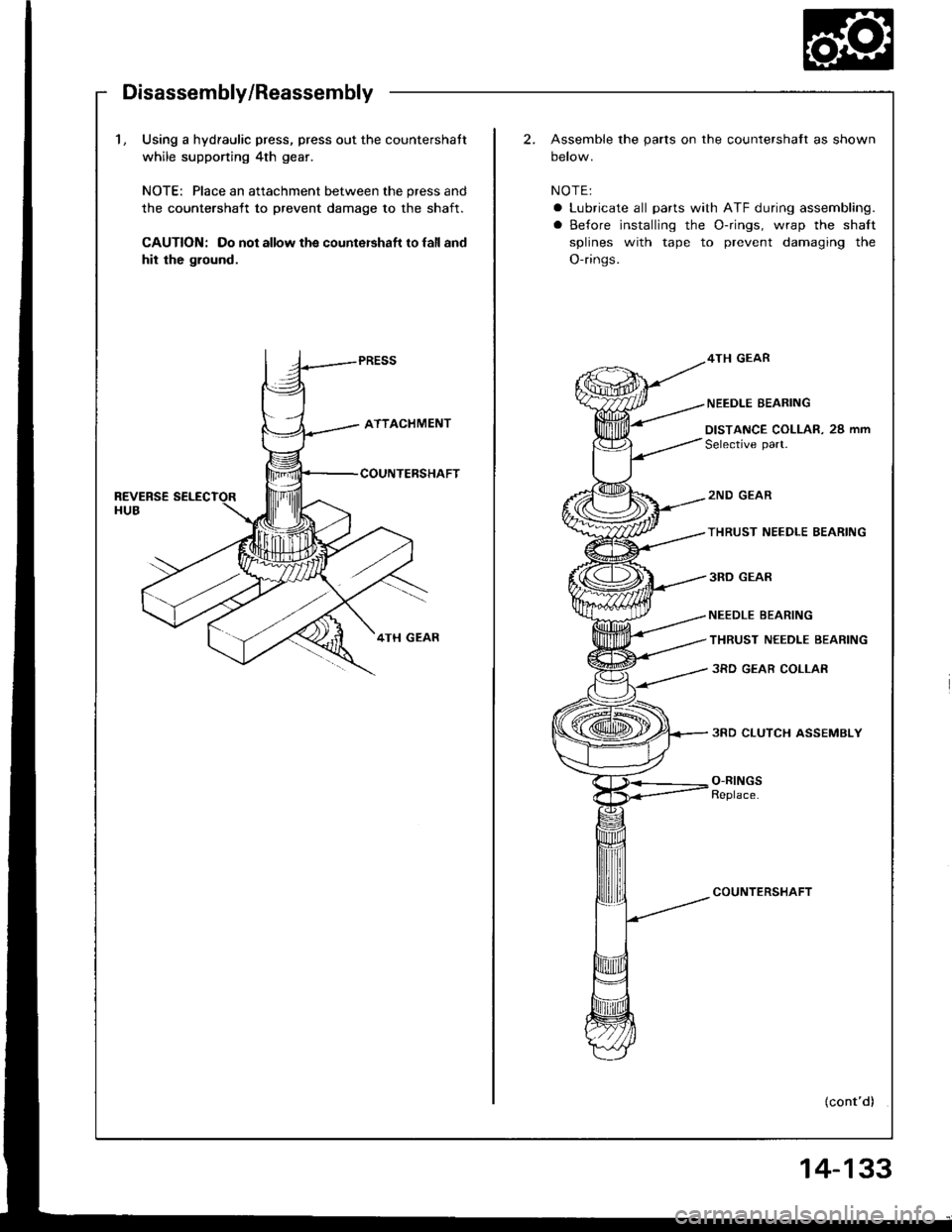
1, Using a hydraulic press, press out the countershatt
while supponing 4th gear.
NOTE: Place an attachment between the press and
the countershatt to prevent damage to the shaft.
CAUTION: Do not allow the countershaft to lall and
hit the ground.
2.Assemble the parts on the countershaft as shown
oetow.
NOTE:
a Lubricate all parts with ATF during assembling.
a Before installing the O-rings, wrap the shalt
splines with tape to prevent damaging the
O-rings.
4TH GEAR
NEEDLE BEARING
DISTANCE COLLAR. 29 mm
Selective part.
2ND GEAR
THRUST NEEDLE BEARING
3RD GEAR
NEEDLE BEARING
THRUST NEEDLE BEARING
3RD GEAR COLLAR
3RD CLUTCH ASSEMBLY
O-RINGSReplace.
COUNTERSHAFT
{cont'd)
Page 526 of 1413
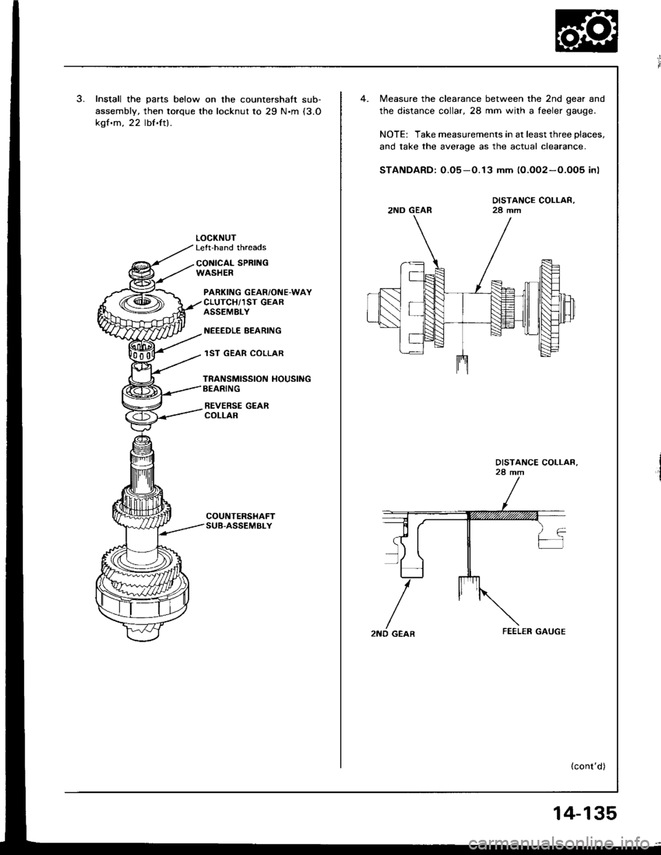
Install the parts below on the countershaft sub-
assembly, then torque the locknut to 29 N'm (3.O
kgf.m, 22 lbf.ft).
LOCKNUTLeft-hand threads
CONICAL SPRI GWASHER
PARKING GEAR/ONE-WAYCLUTCH/1ST GEARASSEMBLY
NEEEDLE BEARING
lST GEAR COLLAR
TRANSMISSION HOUSINGBEARING
REVERSE GEARCOLLAR
Measure the clearance between the 2nd gear and
the distance collar, 28 mm wilh a feeler gauge.
NOTE: Take measurements in at least three places.
and take the average as the actual clearance.
STANDARD: O.O5-0.13 mm (0.OO2-O.O05 in)
DISTANCE COLLAR,28 mm2ND GEAR
2ND GEAR
(cont'd)
14-135
Page 528 of 1413
One-way Clutch/Parking Gear
Disassembly/lnspection
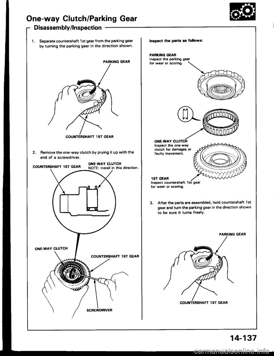
1.Separate countershaft 1st gear from the parking gear
by turning the parking gear in the direction shown.
Inspoct tha psrta a3 tollows:
PARKII{G GEARInspect thg parking
tor w€s. or acoring.
O E.WAY
2. Remove the one-way clutch by prying it up with the
end of a screwdrive..
Inspect tho ono-wayclutch fo. damagea orfaultv movement.
courrERsHAFrlsr.EAR 9IlYlL9iY^t.?INOTE: lnstall in this direction.
l ST GEARInspect counior6haft 1tor wegr or scoaing.
3. After the Darts are sssembled, hold counte.shaft lst
gear and turn tho parking gear in the direction shown
to be sur6 it turns freelv,
O'TE.WAY CLUTCH
COUNTERSHAFT lST GEAR
COUNTERSHAFT 1ST GEAR
COU TERSHAFT 1ST GEAR
SCREWDRIVER
14-137
Page 529 of 1413
Sub-shaft
Disassembly/lnspection/Reassembly
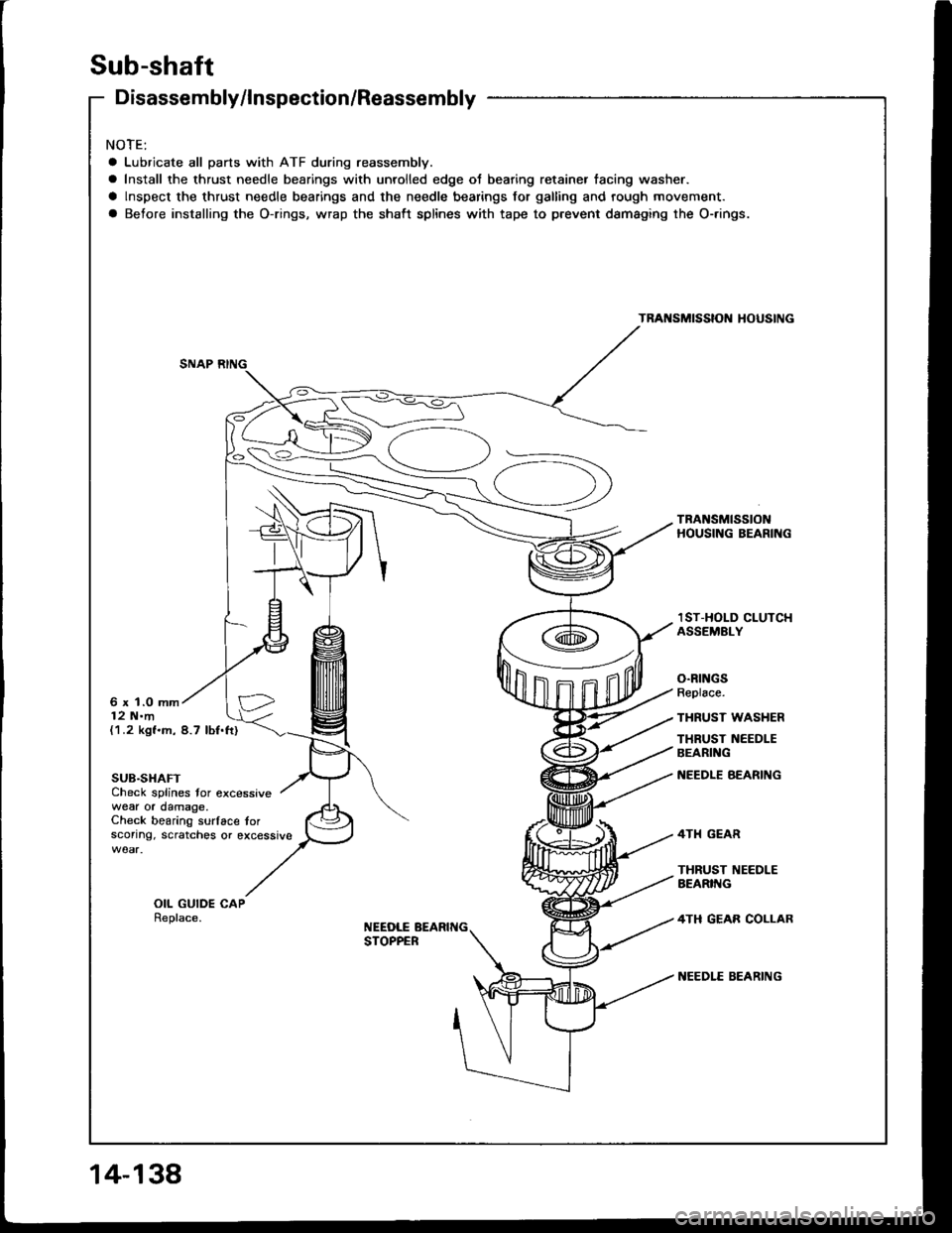
NOTE:
a Lubricate all parts with ATF during reassembly.
a Install the thrust needle bearings with unrolled edge ot bearing retainer tacing washer.
a lnspect the thrust needle bearings and the needle bearings for galling and rough movement.
a Before installing the O-rings, wrap the shaft splines with tape to prevent dsmaging the O-.ings.
TRANSMISSIOI{ HOUSING
TRANSMISSIONHOUSING BEARING
6 x 1.0 mm12 N.m
lST-HOLD CLUTCHASSEMELY
O.RINGSReplace.
THRUST WASHER
THRUST NEEDLEBEARING
NEEDLE BEARING
4TH GEAR
THRUST I{EEDLEAEARIIIG
4TH GEAB COLLAR
NEEDLE EEARING
(1.2 kgf.m, 8.7 lbf.ft)
SUB.SHAFTCheck splines tor excessivewear or damage.Check bearing surlace torsconng. scratches or excessive
OIL GUIDE CAPReplace.NEEDLE BEARIT{GSTOPPER
Page 530 of 1413
Disassembly/Reassembly
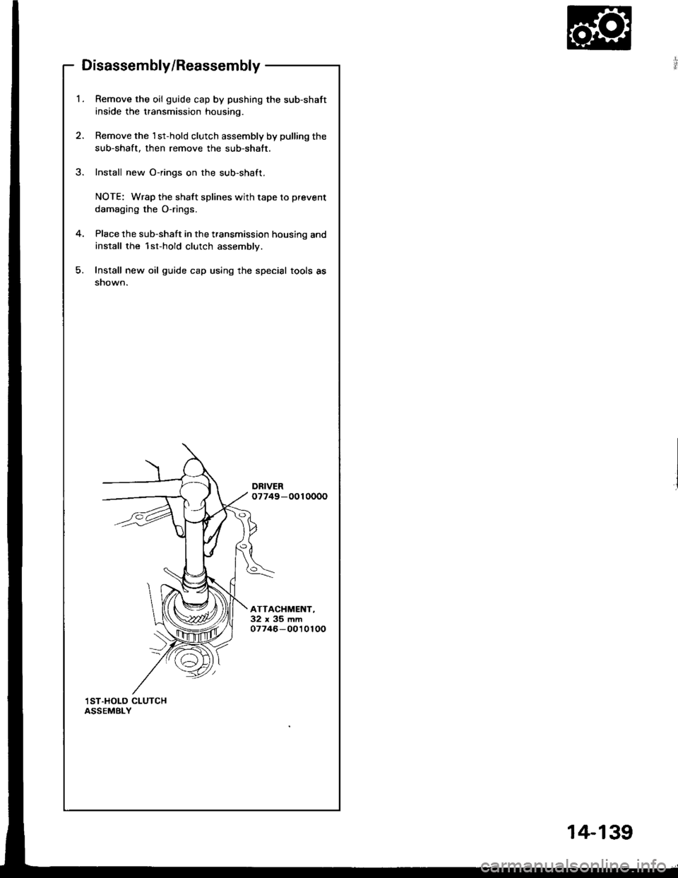
Remove the oil guide cap by pushing the sub-shaft
inside the transmission housing.
Remove the 1st-hold clutch assembly by pulling the
sub-shaft, then remove the sub-shatt.
Install new O-rings on the sub-shaft.
NOTE: Wrap the shaft splines with tape to prevent
damaging the O-rings.
Place the sub-shaft in the transmission housing and
install the 1st-hold clutch assembly.
Install new oil guide cap using the special tools as
snown.
DRIVER07749-0010000
ATTACHMENT-32x35mm07746-0010100
,I ST.HOLD CLUTCHASSEMBLY
14-1 39
Page 532 of 1413
Clutch
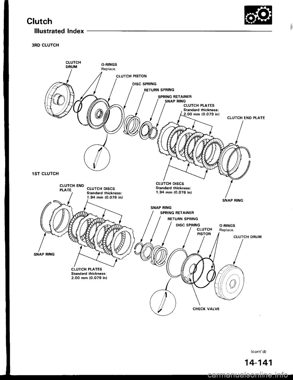
lllustrated Index
3RD CLUTCH
CLUTCHDRUMO-RINGSReplace.
CLUTCH DISCSStsndard thickness:1.94 mm {0.076 in)
CLUTCH PISTON
DISC SPRING
RETURN SPRING
SPRING RETAINERSNAP RING
1ST CLUTCH
SNAP RING
CLUTCH ENDPLATE
O-RINGSReplace.
CLUTCH PLATESStandard thicknass:2.00 mm {0.079 in}
(cont'd)
SNAP RING
SNAP RING
CHECK VALVE
14-141
Page 533 of 1413
Clutch
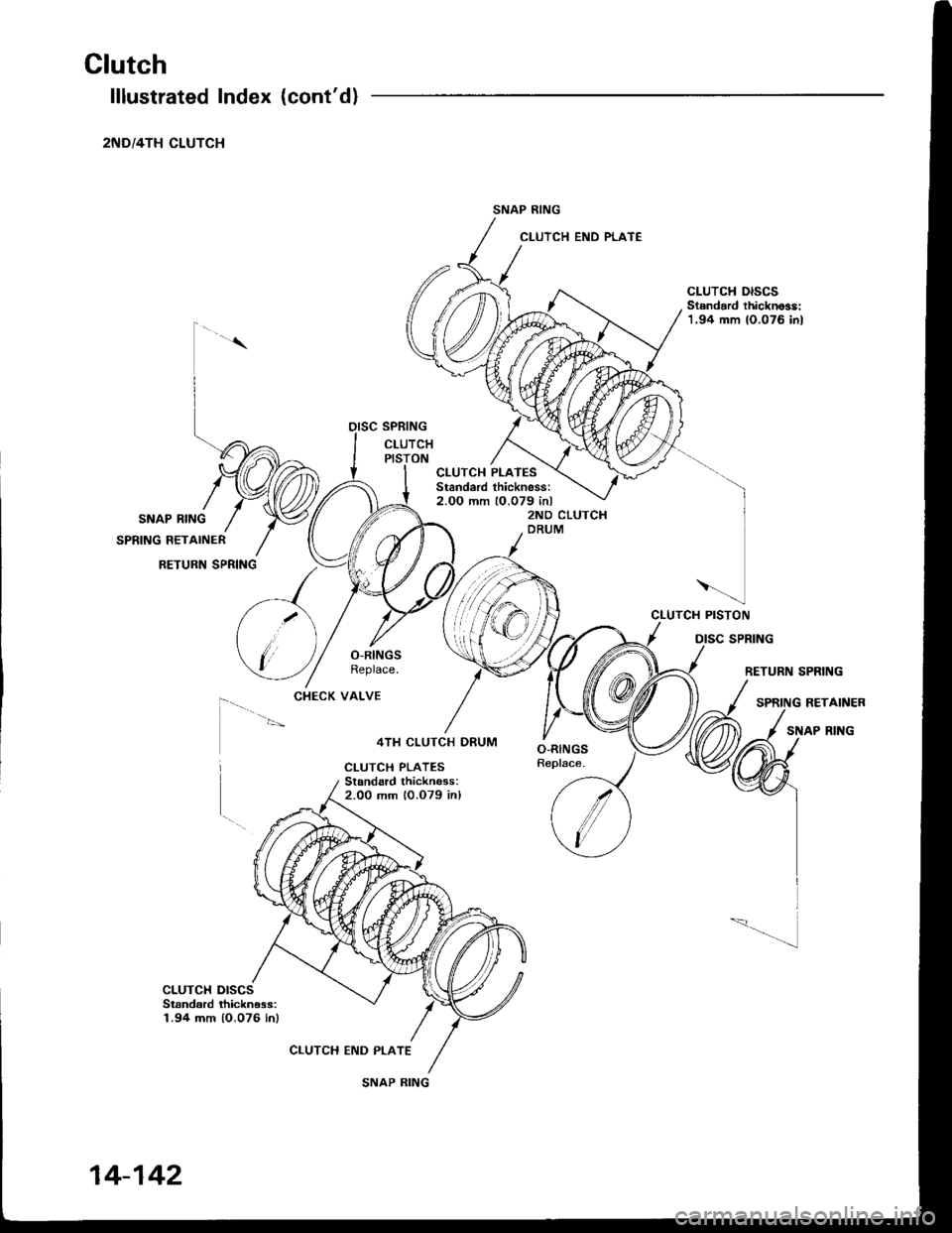
lllustrated Index (cont'd)
2ND/4TH CLUTCH
SNAP RING
SPRING RETAINER
RETURN SPRING
CLUTCH END PLATE
4TH CLUTCH DRUM
CLUTCH PLATESStanda.d thickness:2.00 mm 10.079 in)
SNAP RING
CLUTCH DISCSStandard thickno3s:1.94 mm 10.076 in)
CLUTCH END PLATE
;;i;;; /
(/\
Y)
)
l
CLUTCH PISTON
CLUTCH PLATESStandard thickness:2.OO mm 10.079 inl
SPRING
RETURN SPRING
RETAINER
SNAP RING
CLUTCH DISCSStsndard ihickn€ss:1.94 mm 10.076 in)
CHECK VALVE
SNAP RING
14-142
Page 534 of 1413
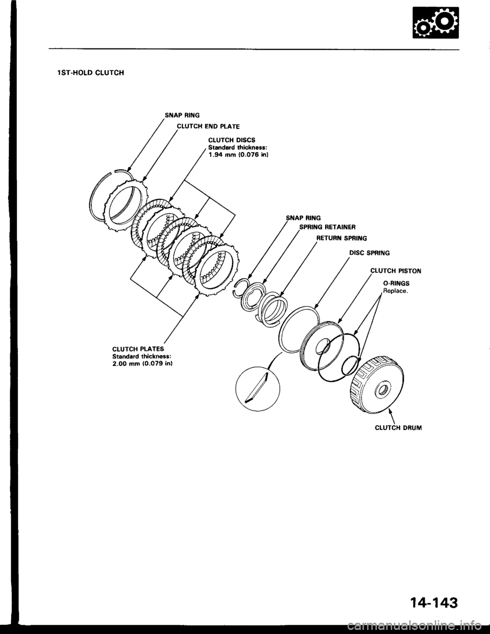
lST.HOLD CLUTCH
SNAP RING
CLUTCH END PLATE
CLUTCH DISCSStandard thicknoss:1.94 mm 10.076 inl
DISC SPRING
CLUTCH PISTON
O-RINGSRoplace.
CLUTCH PLATESStandard thickno3si2.00 mm (0.o79 in)
14-143
Page 535 of 1413
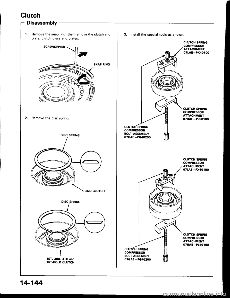
Disassembly
Clutch
Remove the snap ring. then.emove the clutch endplate, clutch discs and plates.
SNAP RII{G
2. Remove the disc spring.
2ND CLUTCH
otsc sPfit c
DISC SPBING
1ST, 3RD, 4TH .ndl ST.HOLD CLUTCH
14-144.
SPNING
3. Install the sDecial tools as shown.
CLUTCH SPRIT{GCOMPRESSORATTACHME ToTLAE-PX40100
cLuTcH spnr cCOMPNESSORATTACHME ToTHAE-Pr60tOO
CLUTCH SPRII{CCOMPNESSORATTACHi'ENTOTLAE-PX,l{,TOO
CLUTCH SPBII{GCOMPRESSORATTACHMEI{ToTHAE-Pt50100

