head HONDA INTEGRA 1994 4.G Manual PDF
[x] Cancel search | Manufacturer: HONDA, Model Year: 1994, Model line: INTEGRA, Model: HONDA INTEGRA 1994 4.GPages: 1413, PDF Size: 37.94 MB
Page 309 of 1413
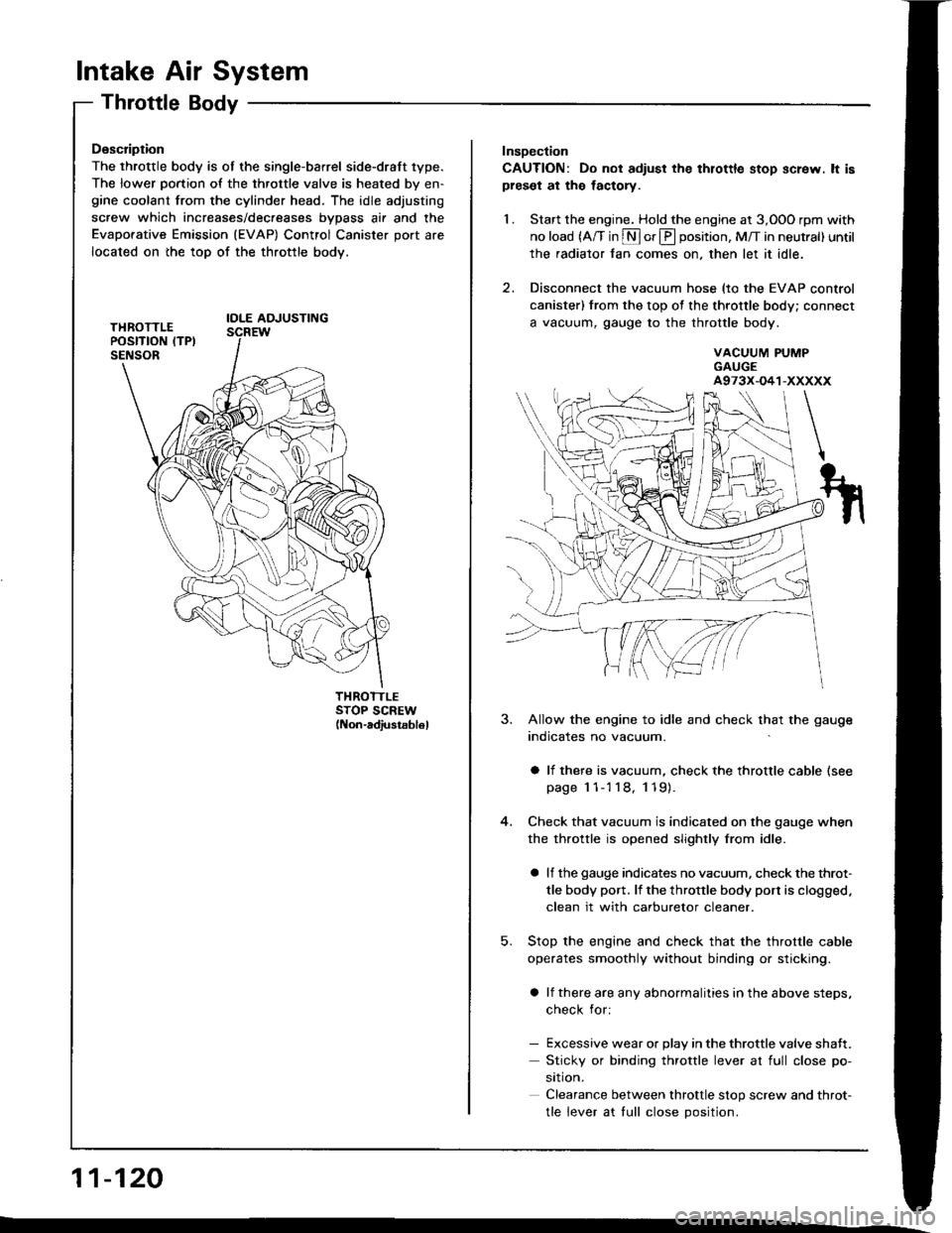
lntake Air System
Throttle Body
Description
The throttle body is ot the single-barrel side-draft 1ype.
The lower portion of the throttle valve is heated by en-gine coolant from the cylinder head. The idle adjusting
screw which increases/dec.eases bvDass air and the
Evaporative Emission (EVAP) Control Canister port are
located on the top of the throttle body.
IOLE AOJUSTING
THROTTLESTOP SCREW(Non-adiustsb16l
11-120
Insoection
CAUTION: Do not adiust the thlottle stop screw. lt ispreset at the lactory.
1. Start the engine. Hold the engine at 3,OOO rpm with
no load (A/T in S or E position, M/T in neutral) until
the radiator fan comes on, then let it idle.
2. Disconnect the vacuum hose (to the EVAP control
canister) from the top of the throttle body; connect
a vacuum, gauge to the throttle body.
VACUUM PUMPGAUGEA973X-O41-XXXXX
5.
3. Allow the engine to idle and check that the gauge
indicates no vacuum.
a li there is vacuum, check the throttle cable (see
page 1 1-'l 18, 119).
Check that vacuum is indicated on the gauge when
the throttle is opened slightly from idle.
a lf the gauge indicates no vacuum, check the throt-
tle body port. lf the throttle body port is clogged.
clean it with carburetor cleaner.
Stop the engine and check that the throttle cable
operates smoothly without binding or sticking.
a lf there are any abnormalities in the above steps,
check for:
- Excessive wear or Dlav in the throttle valve shaft.
Sticky or binding throttle lever at full close po-
srtron.
Clearance between throttle stop screw and throt-
tle lever at tull close Dosition.
Page 319 of 1413
Emission Control System
SystemDescription
The emission control system includes a Three Way Cata-
lytic Convener (TWC), Positive Crankcase Ventilation(PCV) system and Evaporstive Emission {EVAP) Contfol
syst€m. The emission control system is designed to meet
federsl and stats emission standards.
Tailpipe Emission
Inspection
f!fifil oo nor amoro ou]rng rnr! Foacqurr. ^!op
any open flame away from yout wotk atca.
Start the engine. Hold the engine at 3,OOO rpm with
no load (A/T in @ or@ position, M/T in neutral) until
the radiator fan comes on, then let it idle,
Connect a tachometer.
Check and adiust the idle speed, if necessary (sss
page 1 1-95).
Warm up and calibrate the CO meter according to
the meter manutacturer's inst.uctions.
Check idle CO with the headlights, hester blower,
rear window defogger, cooling fan, and air condition-
er otf.
NOTE: (Canada) Pull the parking br8ke lever up.
Stan the engine, then check that the headlights are
off.
CO meter should indicate 0.1 maximum.
11-130
Page 379 of 1413
Countcr'h!ft:
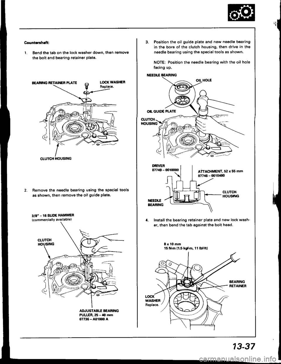
'1. Bsnd the tab on the lock washer down, then remove
the bolt 8nd bearing retainer plate.
Remove th€ needle bearing using the specisl
as shown, then remove the oil guide pl8te.
3rE' - 16 SUI'€ HAiiMER
{commorcially availabls)
lools
AD.'USTABII BEARIITGPULIIR, 25 - ao mm07t36 - A0rm0 a
CLUTCH HOUSING
3. Position the oil guide plate and new needle bearing
in the bore of the clutch housing, then drive in the
needle bearing using the specialtools as shown.
NOTE: Position the needle bearing with the oil hole
facing up.
OIL GUIDC PLATE
CI-UTCHHOUSING
Install the bearing retainer plate and new lock wash-
er, then bend the tab againstthe bolt head.
8x 10 mm15 N.m ll.5 kd.m, 11 lbf.ttl
LOCKWASHEARepl6ce.
13-37
Page 549 of 1413
18. Install the sub-shaft assembly in the transmission
housing {see page 14-138).
19- Install the reverse idler gear and gear shatt holder
(see page 14-154).
20. Install the differential assembly in the torque con-
verter housing.
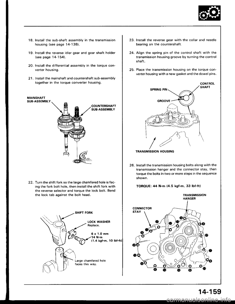
21. Install the mainshaft and countershaft sub-assembly
together in the torque converter housing.
MAINSHAFTSUB.ASSEMBLY
COUNTERSHAFTSUB.ASSEMBLY
22.Turn the shift fork so the large chamtered hole is fac-
ing the fork bolr hole. then installthe shift fork with
the reverse selector and torque the lock bolt. Bend
the lock tab against the bolt head.
SHIFT FORK
LOCI( WASHERReplace.
6 x 1.0 mm4 N.m(1.4 kgl.m, rO lbt.ft)
Large chamfered holefaces this way.
,,1
24.
lnstall the reverse gear with the collar and needle
bearing on the countershalt.
Align the spring pin of the control shaft with the
transmission housing groove by turning the control
shalt.
Place the transmission housing on the torque con-
verter housing with a new gasket and the dowel pins.
CONTROL
/K"\
//2"\TRANSMISSION HOUSING
Install the transmission housing bolts along with the
t.ansmission hanger and the connector stay, then
torque the bolts in two or more steps in the sequence
shown.
TOROUE: 44 N.m (4.5 kgf.m, 33 lbf'ft)
TRANSMISSIONHANGER
25.
CONNECTOR
14-159
Page 616 of 1413
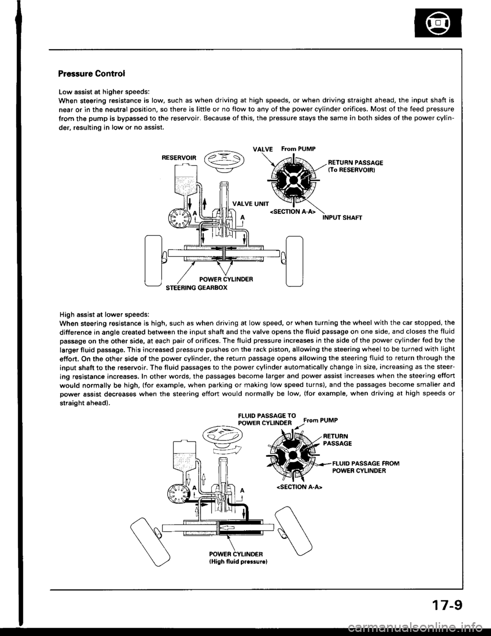
Pressure Control
Low assist at higher speeds:
When steering resistance is low. such as when driving at high speeds. or when driving straight ahead, the input shaft is
near or in the neutral position, so there is little or no flow to any of the power cylinder orifices, Most of the feed pressure
trom the pump is bypassed to the reservoir. Because of this, the pressure stays the same in both sides of the power cylin-
der, resulting in low or no assist.
vaz =- S\->/-\7/RETURN PASSAGE(To RESERVOIRI
VALVE UNIT
High assist at lower speeds:
When steering resistance is high, such as when driving at low speed, or when turning the wheel with the car stopped, the
difference in angle created between the input shaft and the valve opens the fluid passage on one side, and closes the fluid
passage on the other side, at each pair of orifices. The fluid pressure increases in the side of the power cylinder fed by the
larger fluid passage. This increased pressure pushes on the rack piston, allowing the steering wheel to be turned with light
effon. On the other side of the power cylinder, the return passage opens allowing the steering fluid to return through the
input shaft to the reservoir. The fluid passages to the power cylinder automatically change in size, increasing as the steer-
ing resistance increases. In other words, the passages become larger and power assist increases when the steering effort
would normally be high, (for example. when parking or making low speed turns). and the passages become smaller and
power assist decreases when the steering effort would normally be low, (for example, when driving at high speeds or
straight ah€ad).
FLUIO PASSAGE TOPOWER CYLINDERFrom PUMP
A
/t-:\
v"
=iJ
RETURNPASSAGE
FLUID PASSAGE FROMPOWER CYLINDER
ALVE F.om PUMP
RESERVOIR
17-9
Page 619 of 1413
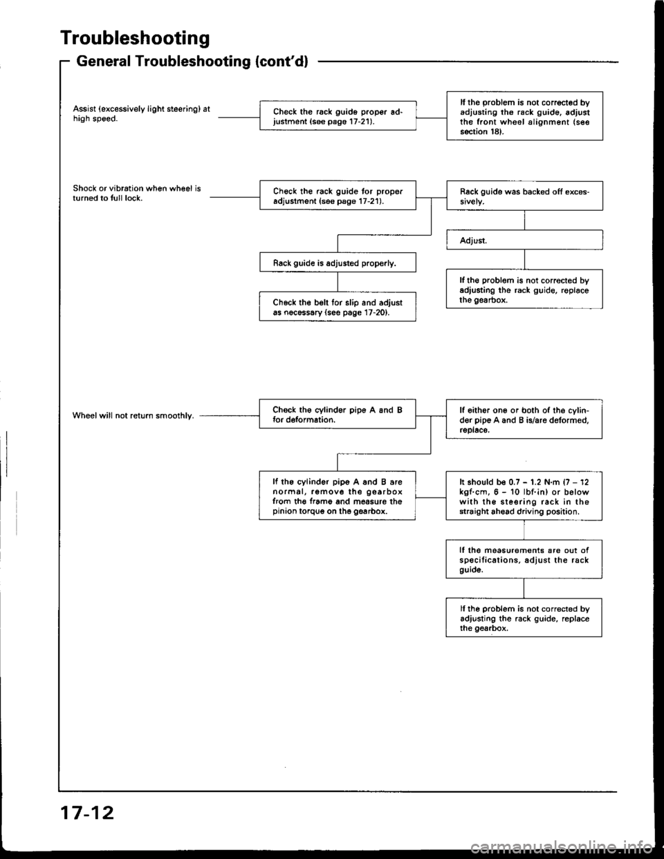
Troubleshooting
General Troubleshooting {cont'd}
Assist (excessively light steering) athigh speed.
Shock or vibration when wheel isturned to tull lock.
Wheelwill not return smoolhly.
ll the problem is not corrected byadjusting th6 rack g!ide. adjustthe front wheel alignment (see
section 18).
Check the rack guido proper ad'justment (see pago 17-21).
Check the rack guide tor properadjustment (ses psge 17-21).
Rack guide is adjusted prop€rly.
lf th€ problem is not correct€d byadiusting the rack guide, roplacethe gesrbox.Ch6ck the belt tor slip and adjustas nocessary (see page 17-20).
lf oither one or both of the cylin-der pip€ A and B is/are deformed,rsplace,
lf the cylinder pip6 A and B arenormal, remove the gearboxfrom th€ f.ame and mossure thepinion torqug on the gearbox.
It should be 0.7 - 1.2 N.m {7 - 12kgf.cm, 6 - 10 lbf.in) or belowwith the sleering rack in thestraight ahead driving position.
lf lhe measurem€nts are out ofspecilications. adjust the rackguid6.
ll ihe problem is not corrected byadjusting the rack guide, replaceihe gearbox.
17-12
Page 628 of 1413
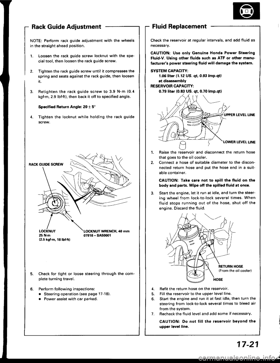
NOTE: Perform rack guide adjustment with the wheels
in the straight ahead position.
Loosen the rack guide screw locknut with the spe-
cialtool, then loosen the rack guide screw.
Tighten the rack guide screw until it compresses the
spring and seats against the .ack guide, then loosen
it.
Retighten the rack guide screw to 3.9 N.m {0.4
kgf'm, 2.9 lbf.ft), then back it off to specified angle.
Specified R6turn Angle: 20 t 5"
Tighten the locknut while holding the rack guide
screw.
1.
6.
RACK GUIDE SCREW
25 N.m12.5 kgf.m, 18lbtftl
L(rcKNUT WRENCH, 40 mm07916 - SAs(xtOl
Check for tight or loose steering through the com-
plete turning travel.
Perform following inspections:
. Steering operation (see page 17-18).
. Power assist with car parked.
Check the reservoir at regular intervals. and add fluid as
necessary.
GAUTION: Use only Genuine Honda Power Stosring
Fluid-V. Using othsr fluids such as ATF or other manu-
facturer's power stoering fluid will damags ths systcm,
SYSTEM CAPACITY:
LO6 litor (1.12 US. qt, 0.93 lmp.qtl
at disasssmbly
RESERVOIR CAPACITY:
0.79 lit6r (0.8:l US. qt, 0.70 lmp.qt)
UPPER LEVEL UNE
LOWER LEVEL LINE
,l
Raise the reservoir and disconnect the return hose
that goes to the oil cooler.
Connect a hose of suitable diameter to the discon-
nected return hose and put the hose end in a suit-
able container.
CAUTION: Tako caro not to 3pill tho tluid on tho
body and parts. Wipe off the spilled tluid at onqe.
Start the engine. let it run at idle. and turn the steer-
ing wheel from lock-to-lock several times. When
fluid stops running out of the hose, shut off the
engine. Discard the fluid,
Refit the return hose on the reservor.
Fill the reservoir to the uDoer level line.
Start the engine and run it at fast idle, then turn the
steering from lock-to-lock several times to bleed air
f.om the system.
Recheck the fluid level and add some if necessary.
CAUTION: Do not lill the roservoir beyond tho
uppgr lovel line.
7.
Page 633 of 1413
Steering Wheel
Installation
Airbag installation
CAUTION:
. B€fore inrtalling the stooring wheel, align tho front
who6l3 etraight ahead.
. Bo sure to install the harness wires so that thGy are
not pinched or intorfsring with othor car parts.
. Do not roplace thc original stsoring wheel with any
othor design. since it will maks it impo$ibla to prop-
erly install the airbag. {Only use genuine HONDA
replscomont parts)
. After rols3embly. confirm thai the whoels are still
straight ahoad 8nd that steoring wheel spoke anglo
is correct. lf minor spoke anglo adiustment is noc€s-
srry, do so qnly by adlustment ol th€ tie-rods, not byromoving and repositioning the steering wh€€|.
@ contirm ihat the airbag assombly is
socurely attachsd to the stooring wheel; oth€rwise,
scvoro porsonal iniury could r€sult during airbag
doploym6nt.
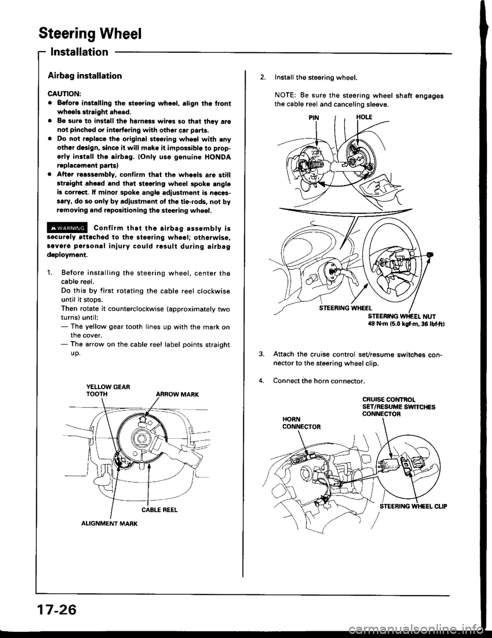
1. Before installing the steering wheel, center the
cable reel.
Do this by tirst rotating the cable reel clockwise
until it stoos.
Then rotate it counterclockwise (approximately two
turnsl until:- The yellow gear tooth lines up with the mark on
the cover.- The arrow on the cable reel label points straight
UD.
YELI-OW GEAR
ALIGNMENT MARK
17-26
2. Install the steering wheel.
NOTE: Be sure the steering wheel shaft engages
the cable reel and canceling sleeve.
a9 N.m (5.0 ksf'm,36 lbf.ftl
Attach the cruise control sevresume switch€s con-nector to the steering wheel clip.
Connect ihe horn connector.
CRUISE CONTROLSET/NESUME SWITCHESCONNECTOR
Page 654 of 1413
11.
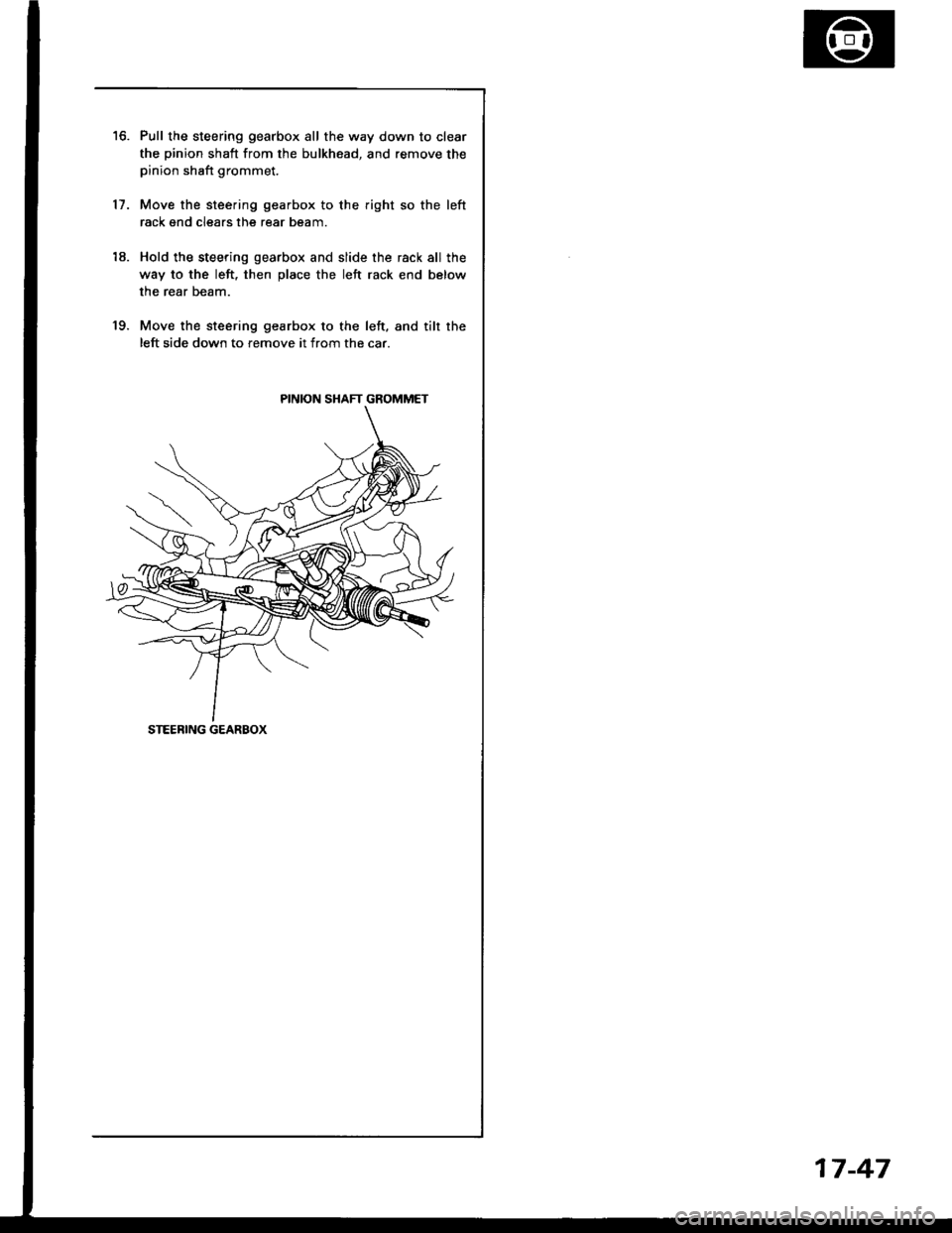
Pull the steering gearbox all the way down to clear
the pinion shaft from the bulkhead, and remove thepinion shaft grommet.
Move the steering gearbox to the right so the left
rack gnd clears the rear beam.
Hold the steering gearbox and slide the rack all the
way to the left, then place the left rack end below
the rear beam.
Move the steering gearbox to the left. and tilr the
left side down to remove it from the car.
18.
19.
PINION SHAFT GROMMET
STEEBING GEARBOX
17-47
Page 670 of 1413
lnstallation
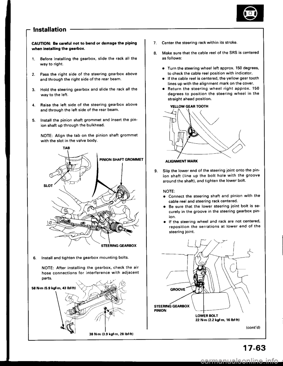
CAUTION; BG Glrc{ul not io bcnd or drm8go tho piping
whcn in3tllling tho gea.box.
1. Before installing the gearbox, slide the rack all the
way to right.
2. Pass the right side of the steering gearbox above
and through the right side of the rear beam.
3. Hold the steering gearbox and slide the rack all the
wav to the left.
4. Raise the left side of the steering gearbox above
and through the left side of the rear beam.
5. Install the pinion shaft grommet and insert the pin-
ion shaft up through the bulkhead.
NOTE: Align the tab on the pinion shaft grommet
with the slot in the valve bodv.
6. Install and tighten the gearbox mounting bolts.
NOTE: After installing the gearbox, check the air
hose connactions for interference with adjacent
pans.
58 N.m 15.9 kg[.m, $ lbl.ftl
TAA
38 N m 13.9 kgl.m, 28 lbt.ftl
17-63
YELLOW GEAR TOOTH
7.Center the steering rack within its stroke.
Make sure that the cable reel of the SRS is centered
as follows:
. Turn the steering wheel left approx. 150 degrees,
to check the cable reel position with indicator.
. lfthe cable reel is centered. the yellow gear tooth
lines up with the alignment mark on the cover.
. Return the steering wheel right approx. 150
degrees to position the steering wheel in the
straight ahead position.
ALIGNMEi'IT MARK
Slip the lower end of the steering joint onto the pin-
ion shaft (line up the bolt hole with the groove
around the shaft), and tighten the lower bolt.
NOTE:
. Connect the steering shaft and pinion with the
cable reel and steering rack centered.
. Be sure that the lower steering ioint bolt is se-
curely in the groove in the steering gearbox pin-
ion.
. lf the steering wheel and rack are not centeted,
reposition the serralions at lower end of the
steering joint.
(cont'dl
22 N.m 12.2 kgi.m, 16lbf.ftlLOWER BOLT