head HONDA INTEGRA 1994 4.G Repair Manual
[x] Cancel search | Manufacturer: HONDA, Model Year: 1994, Model line: INTEGRA, Model: HONDA INTEGRA 1994 4.GPages: 1413, PDF Size: 37.94 MB
Page 133 of 1413
Valve Guides
Replacement (cont'dl
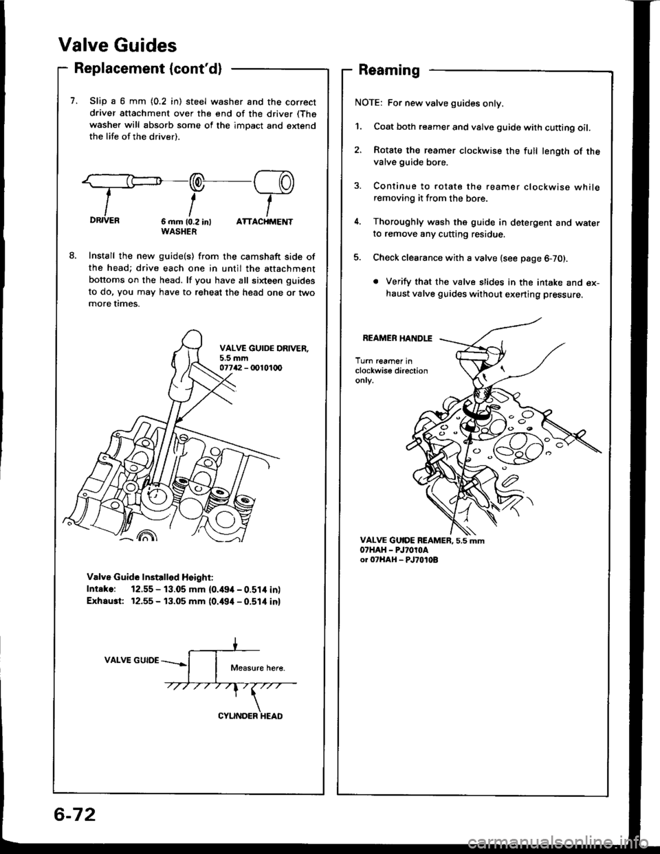
7. Slip a 6 mm {0.2 in) steel washer and the correct
driver attachment over the end of the driver (The
washer will absorb some of the imDact and extendthe life of the driver).
:=:-/--PDRIVER6 mm 10.2 int ATTACHMENTWASHER
Install the new guide(s) from the camshaft side ofthe head; drive each one in until the attachment
bottoms on the head. lf you have all sixteen guides
to do, Vou may have to reheat the head one or twomore times.
Valve Guide Installed Height:
Intake: 12.55 - 13.05 mm {0.49it - 0.51it inl
Exhaust 12.55 - 13.05 mm {0.494 - 0.514 inl
VALVE GUIDE
Reaming
NOTE: For new valve guides only.
1. Coat both reamer and valve guide with cutting oil.
2, Rotate the reamer clockwise the full length of thevalve guide bore.
3. Continue to rotate the reamer clockwise whileremoving it from the bore.
4. Thoroughly wash the guide in detergent and waterto remove any cutting residue.
5. Check clearance with a valve (see page 6-70).
. Verify that the valve slides in the intake and ex-haust valve guides without exerting pressure.
REAMER HANDLE
Turn reamer inclockwise directiononry.
C'
o
a
-'{)
6-72
Page 134 of 1413
Valve Seats
Reconditioning
Renew the valve seats in the cylinder head using
valve seat cutters.
NOTE: lf guides are worn, replace them before cut-
ting the valve seats.
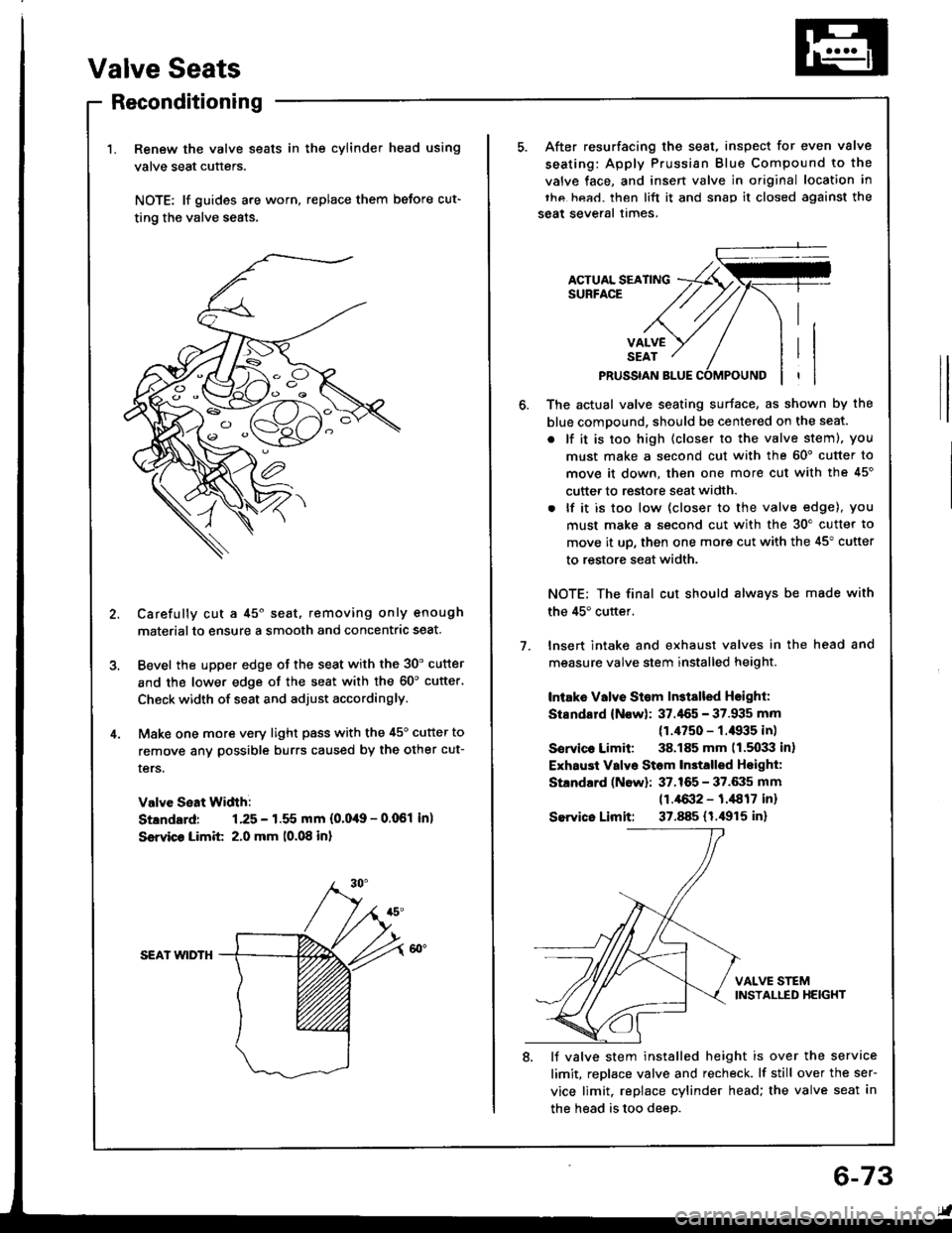
Carefully cut a 45o seat, removing only enough
materialto ensure a smooth and concentric seat.
Bevel the upper edge of the seat with the 30' cutter
and the lower edge of the seat with the 60'cutter'
Check width of seat and adjust accordingly.
Make one more very light pass with the 45o cutter to
remove anv possible burrs caused by the other cut-
ters.
Valve Seat Width:
Stlndard: 1.25 - 1.55 mm {0.0,19 - 0.061 in)
Ssrvico Limit 2.0 mm 10.08 in)
SEAI wlDTH
After resurfacing the seat, inspect for even valve
seating: Apply Prussian Blue Compound to the
valve face, and insen valve in original location in
thc hea.l. then lift it and snap it closed against the
seat several times.
ACTUAL SEATINGSURFACE
VALVESEAT
PRUSSIAN BLUE
1.
The actual valve seating surface, as shown by the
blue compound, should be centered on the seat.
. lf it is too high (closer to the valve steml, you
must make a second cut with the 60' cutter to
move it down, then one more cut with the 45'
cutter to restore seat width.
. lf it is too low (closer to the valve edge), you
must make a second cut with the 30'cutter to
move it up, then one more cut with the 45" cutter
to restore seat width.
NOTE; The final cut should alwavs be made with
the 45'cuttef.
lnsert intake and exhaust valves in the head and
measure valve stem installed height.
Intake Vllve St€m ln3tslled Hsighl:
Stsndard (Now): 37.'155 - 37.935 mm
(1.4750 - f .il935 in)
Sorvico Limit: 38.185 mm 11.5033 in)
Exhaust Valvo Stom In3talled Hoight:
Standard (Now): 37.165 - 37.6:15 mm
11.4{X}2 - 1.,1817 inr
Sewico Limit: 37.885 (1.i1915 in)
VALVE STEMINSTALLED HEIGHT
8. lJ valve stem installed height is over the service
limit, replace valve and recheck. lf still over the ser-
vice limit. replace cylinder head; the valve seat in
the head is too deeD.
6-73
Page 135 of 1413
Gylinder Head
Warpage
NOTE: lf camshaft-to-holder oil clearances (see page
6-65) are not within specification. the head cannot be
.esurfaced.
lf camshaft-to-holder oil clearances are within sDecifica-
tions, check the head for warpage.
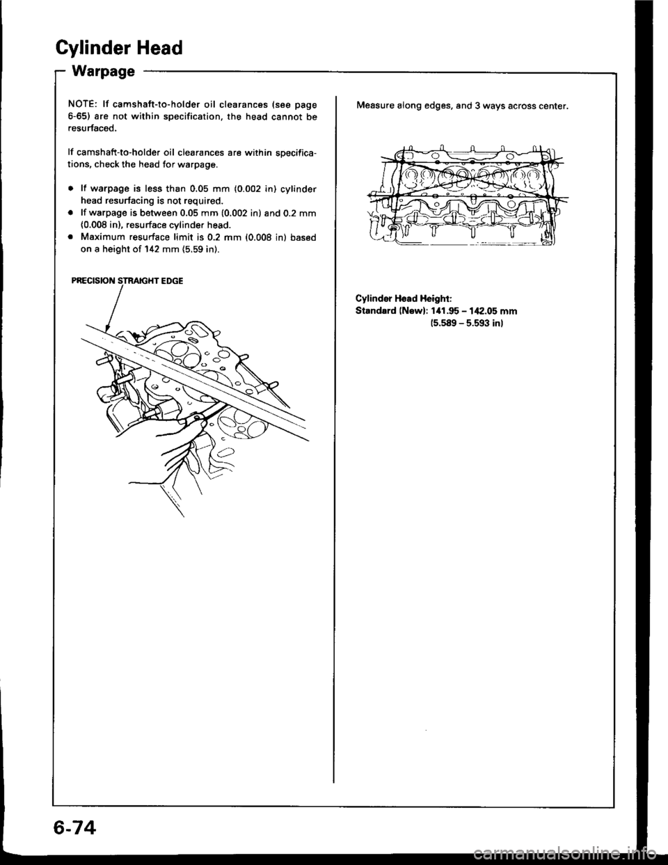
Measure along edges. and 3 ways across center.
lf warpage is less than 0.05 mm {0.002 in) cylinder
head resurfacing is not required.
lf warpage is between 0.05 mm {0,002 in) and 0.2 mm
{0.008 in), resurface cvlinder head.
Maximum resurface limit is 0.2 mm {0.008 in) based
on a height of 142 mm (5.59 in).
PRECISION STRAIGHT EDGE
Cylindsr Hssd Height:
Standard lNsw): 1i11.95 - 1,f2.05 mm
15.s89 - 5.593 inl
6-74
Page 136 of 1413
lnstallation
Installthe cylinder head in the reverse order of removal:
NOTE:
. Always use a new head and manifold gasket.
. The cylinder head gasket is a metal gasket Take care
not to bend it.
. Rotate the crankshaft, set the No. 1 piston at TDC
(page 6-51).
. Do not use the middle cover and lower cover for
storing items disassembled.
. Clean the middle cover and lower cover before instal-
lation.
a Replace the washer when damaged or deteriorated
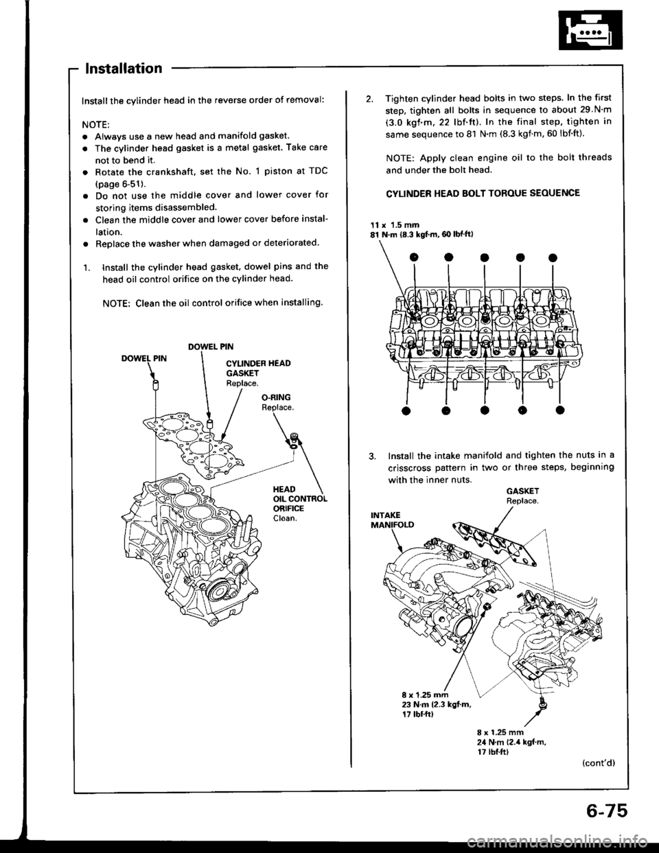
1. tnstall the cylinder head gasket. dowel pins and the
head oil control orifice on the cylinder head
NOTE: Clean the oil control orifice when installing.
O.RINGReplace.
HEADOIL CONTROLORIFICECloan.
2. Tighten cylinder head bolts in two steps. In the first
step, tighten all bolts in sequence to about 29 N'm
(3.0 kgf.m.22 lbf'ft). In the final step, tighten in
same sequence to 81 N.m (8.3 kgnm.60 lbf'ft).
NOTE: Apply clean engine oil to the bolt threads
and under the bolt head.
CYLINDER HEAD BOLT TOROUE SEOUENCE
11 x 1.5 mm81 N.m {8.3 kgf.m,60 lbf ft)
Install the intake manifold and tighten the nuts in a
crisscross pattern in two or three steps, beginning
with the inner nuts.
GASKETRePlace
8 x 1.25 mm23 N.m 12.3 kgl.m.17 tbf.ftt
8 x 1.25 mm24 N,m 12.,4 kgf m,17 tbf.ft)(cont'd)
6-75
Page 137 of 1413
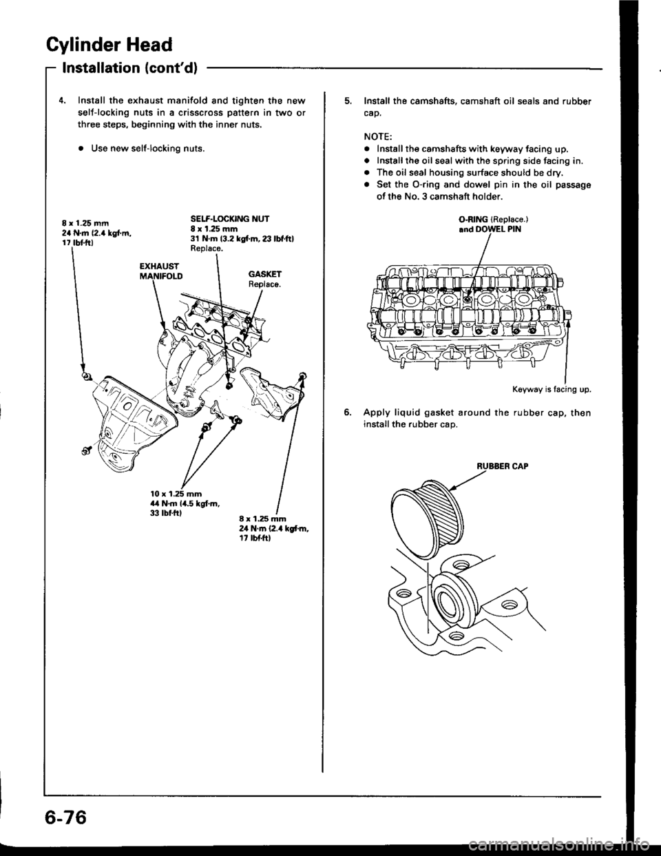
Cylinder Head
8 r 1.25 mm2a N..n 12.4lgtm,r 7 tbf.ftl
Installation {cont'd)
4. Install the exhaust manifold and tighten the new
selJ-locking nuts in a crisscross pattern in two or
three steps, beginning with the inner nuts.
. Use new self-locking nuts.
SELF.LOCKING NUT8 x 1.25 mm31 N.m 13.2 kgf'm, 23 lbtltlReplace.
EXHAUST
a.l N.m 14.5 kgt m,33 tbr.trl
GASKETReplsco.
8 x 1.25 mm24 N.m (2.4 kgt m,rt tbfft)
&,x
6-76
5. Install the camshafts, camshaft oil seals and rubber
cap.
NOTE:
. Install the camshafts with keyway facing up.
o Installthe oil sealwith the spring side facing in.
. The oil seal housing surface should be dry,
. Set the O-ring and dowel pin in the oil passage
of th€ No. 3 camshaft holder
Kgyway is lacing up.
Apply liquid gasket around the rubber cap, then
install the rubber cap.
O-RING {ReDlace.)
Page 138 of 1413
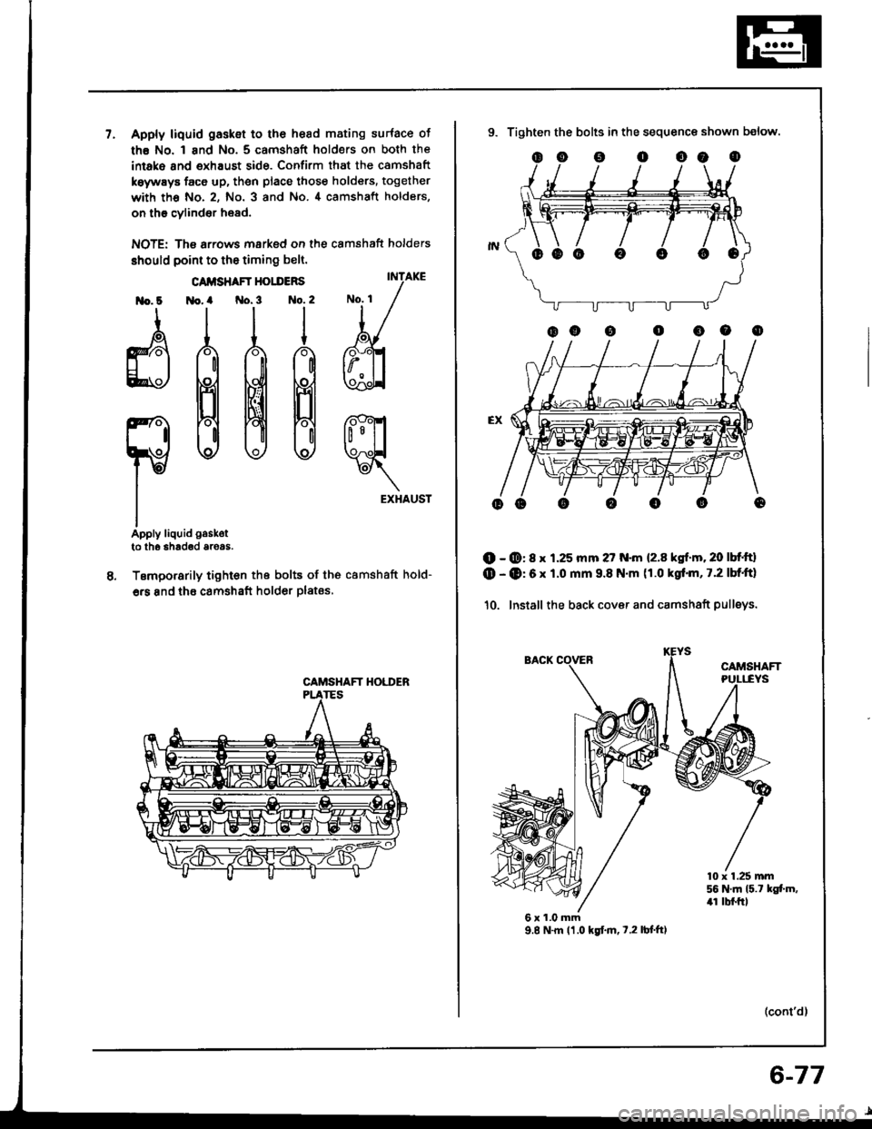
7.Apply liquid gasket to the hesd mating surface of
th€ No. 1 and No. 5 camshaft holders on both the
intako and exhaust side. Confirm that the camshaft
koywEys face up, then place those holders, together
with th€ No.2, No. 3 and No.4 camshaft holders,
on th€ cylind6r head.
NOTE: The arrows msrked on the camshaft holders
should point to the timing belt.
INTAKE
t/
bl
ffi
rfl?x
rt
EXHAUST
Apply liquid gaskot
to lh6 3had€d aroas.
Temporarily tighton the bolts of tho camshaft hold-
6rs and thE camshaft holder plates,
lrlo. 6
d
ro
I
CAIISHAFT HOIDERS
Ho. a No.3 1to.2
rllttt
888
CAMSHAFT HOI,I'ER
9. Tighten the bolts in the sequence shown below.
(D - @: 8 x 1.25 mm 27 N.m {2.8 kgf.m,20 lbt ttl
(D - (D: 6 x 1.0 mm 9.8 N.m (1.0 kgrl.m, 7.2 lbf'ft}
10. Install the back cover and camshaft pulleys.
CAMSHAFT
ooooo0o
10 x 1.25 mm56 N.ln l5.t kgf.m,4r lbl.trl
6x1.0mm9.8 N.m 11.0 kgtm, t.2lbf'ft)
(cont'd)
6-77
Page 139 of 1413
11.
12.
13.
Cylinder Head
Installation lcont'd)
lnstallthe timing belt lsee page 6-51).
Adjust the valve clearance (see page 6-44).
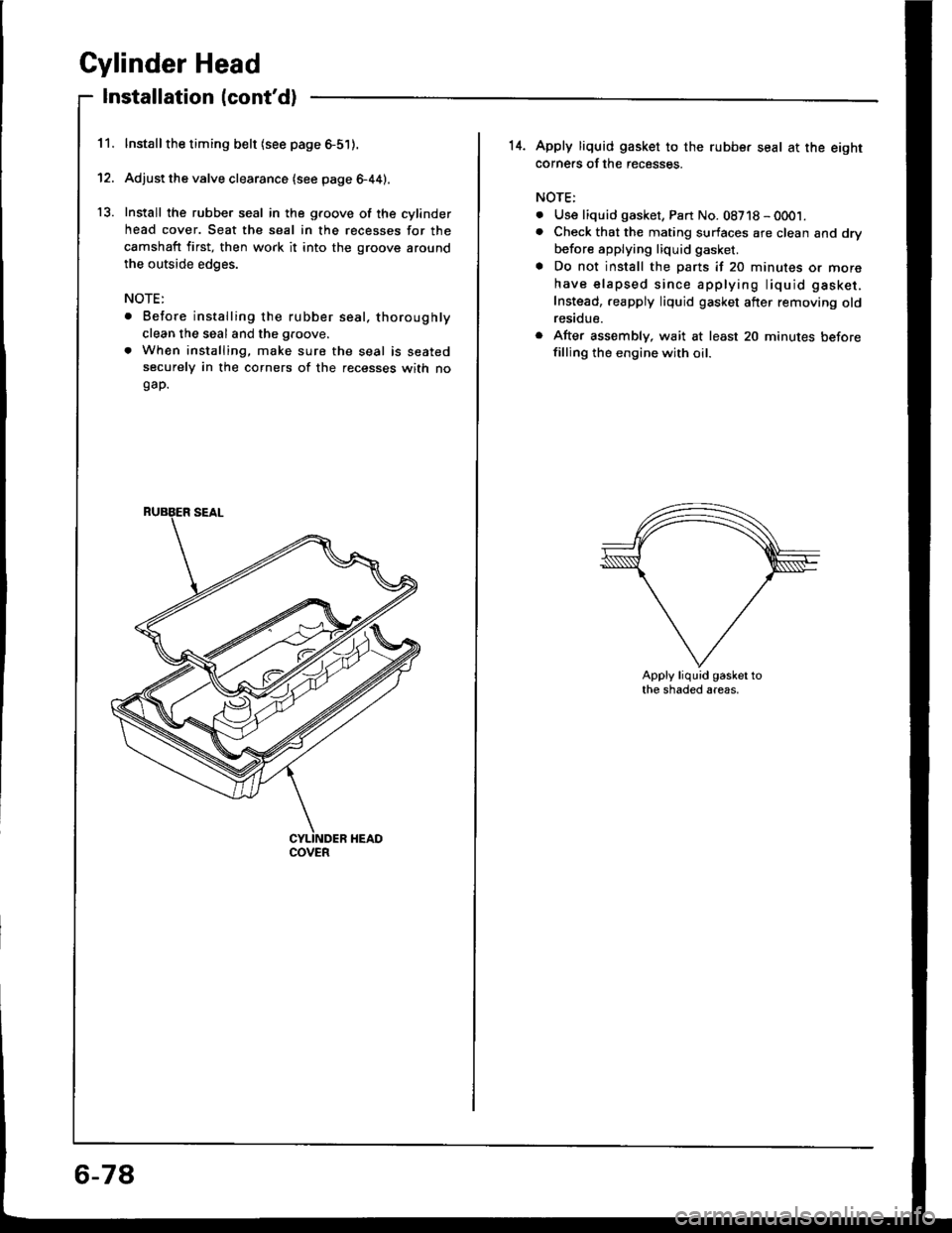
Install the rubber seal in the groove of the cylinder
head cover. Seat the seal in the recesses for the
camshaft first, then work it into the groove around
the outside edges.
NOTE:
. Before installing the rubber seal. thoroughly
clean the seal and the groove.
. When installing, make sure the seal is seatedsecurely in the corners of the recesses with nogap.
COVER
6-78
14. Apply liquid gasket to the rubbe. seal at the eightcorne.s of the recesses.
NOTE:
. Use liquid gasket, Part No. 08718 - 0001.. Check that the mating surfaces are clean and dry
before applying liquid gasket.
a Do not install the parts if 20 minutes or more
have elapsed since applying liquid gasket.
Instead,.eapply liquid gasket after removing oldresidue.
r After assembly, wait at least 20 minutes beforefilling the engine with oil.
Apply liquid gasket tothe shaded areas.
Page 140 of 1413
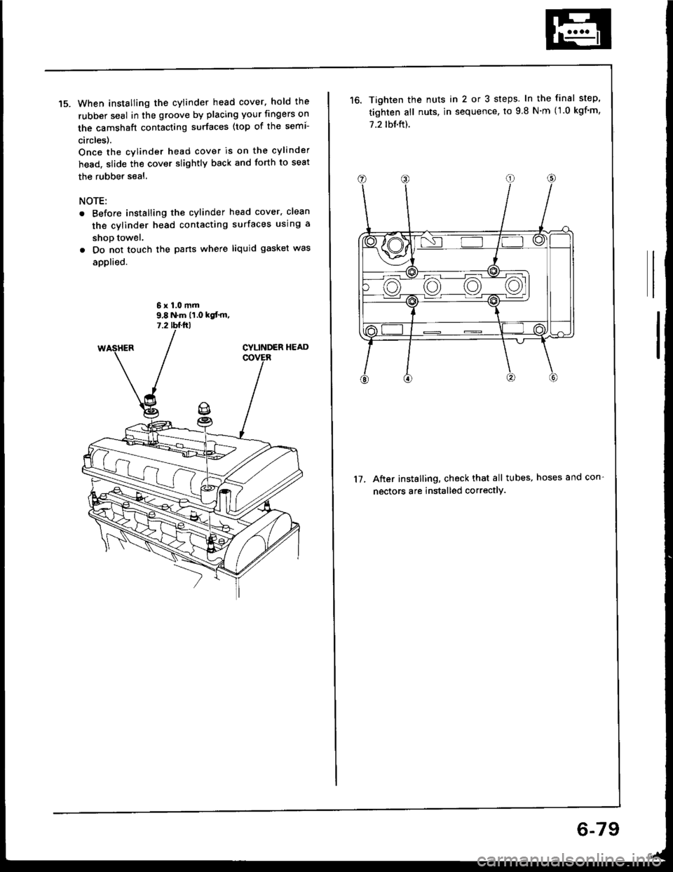
When installing the cylinder head cover. hold the
rubber seal in the groove by placing your fingers on
the camshaft contacting surfaces (top of the semi-
circles).
Once the cylinder head cover is on the cylinder
head, slide the cover slightly back and forth to seat
the rubber seal.
NOTE:
Before installing the cylinder head cover, clean
the cylinder head contacting surfaces using a
shop towel.
Do not touch the pans where liquid gasket was
applied.
6x1.0mm9,8 N.m 11.0 kgt'm,7.2 tffirl
Tighten the nuts in 2 or 3 steps. In the final step'
tighten all nuts, in sequence, to 9.8 N'm (1.0 kgf'm,
7.2 tbf.ft).
After installing, check that all tubes, hoses and con-
nectors are installed correctly.
17.
6-79
Page 142 of 1413
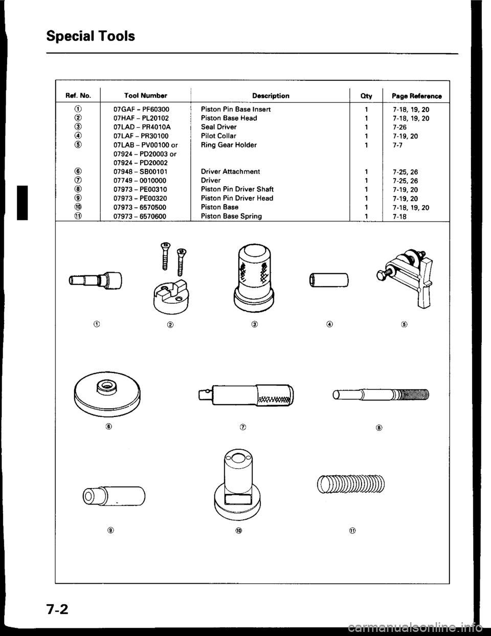
Special Tools
I
Raf. No. I Tool NumbcrDcacriptionOty I Pago Rotcrenc.
o
@
@
@
o
@
o
@
o
@
o
07GAF - PF60300
07HAF - P120102
OTLAD _ PR4O1OA
07LAF - PR30100
07LAB - PV00100 or
07924 - PD20003 or
01924 - PD20002
07948 - S800101
07749 - 0010000
07973 - PE00310
07973 - PE00320
07973 - 5570500
07973 - 6570600
Piston Pin Ease lnsert
Piston Base Head
Seal Oriver
Pilot Collar
Ring Gear Holder
Driver Attachment
Driver
Piston Pin Driver Shaft
Piston Pin Driver Head
Piston Base
Piston Base Spring
1
I
1'I
1
1
1
1
1
1
1
7-14,19,20
1-18, 19,20
7-19,20
7-1
7 -25, 26
7-19,20
1-19.20
1-18, 19, 20
1-18
Eg
o@,a\
o@
@@
0
7-2
Page 158 of 1413
Piston Rings
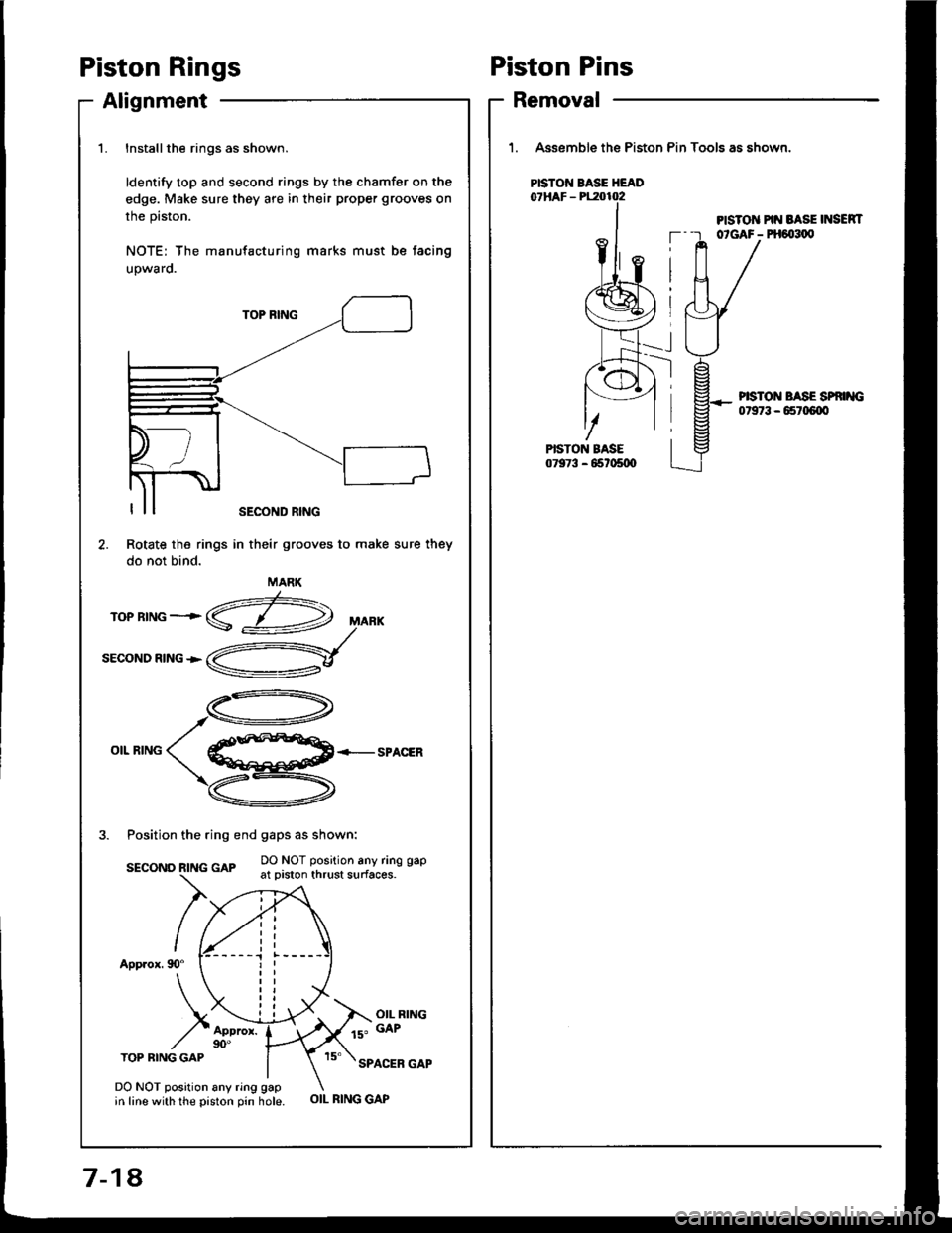
Alignment
1.Installthe rings as shown.
ldentify top and second rings by the chamfer on the
edge. Make sure they are in their proper grooves on
the prston.
NOTE: The manufacturing marks must be facing
upwaro.
TOP BING
OIL RINGSPACER
3. Position the ring end gaps as shown:
DO NOT position any ring gapsEcoNo R|NG GAp -.- :': :.-"' : - ' '----'-- { _- - - at prston thrust surfaces.
App.ox. 90"
OIL RING
ls" GAP
TOP BING GAPSPACER GAP
Rotate the rings
do not bind.
DO NOT position any ring gapin line with the piston pin hole.
SECOND RING
in their grooves to make sure they
MARK
OIL RING GAP
Piston Pins
Removal
1. Assemble the Piston Pin Tools as shown.
PISTO]T PIN BASE INSEN|T--r otGAF- PH6{t1,0
PISTON BASE HEAD
--l
PISTON BASE SP '{G07973 - 65r06{X'
7-18,