head HONDA INTEGRA 1994 4.G Service Manual
[x] Cancel search | Manufacturer: HONDA, Model Year: 1994, Model line: INTEGRA, Model: HONDA INTEGRA 1994 4.GPages: 1413, PDF Size: 37.94 MB
Page 117 of 1413
Cylinder Head
Removal (cont'd)
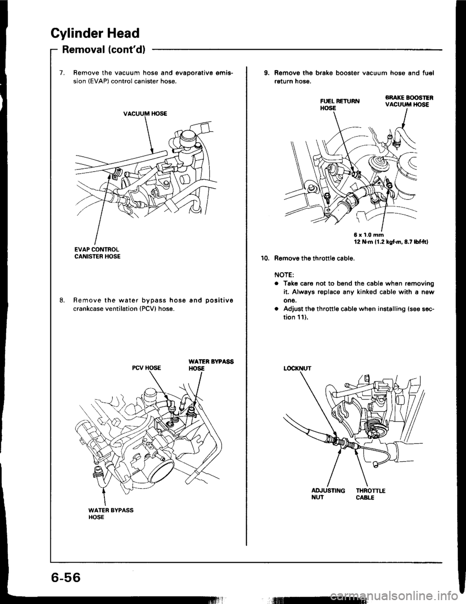
7. Remove the vacuum hose and €vaoorativs emis-
sion (EVAP) control canister hose.
EVAP CONTROLCANISTER HOSE
Remove the water bypass hose and positive
crankcase ventilation {PCV) hose.
WATER BYPAssHOS€PCV HOSE
9. Remove ths brake booster vacuum hose and fu€l
return hose,
BRAKE BOOSTERVACUUM HOSE
6x1.0mm12 N.m 11.2 kgf.n,8.t lbf.trl
10. R€mov6 tho thronlo cable.
NOTE:
o Taks care not to bsnd the cabl6 when removing
it. Always replace any kinked cable with a new
on6.
o Adiust the th.ottle cable when installing (see s6c-
tion 1l).
AD.'USTING THROTTI,"ENUT CABI.T
Page 118 of 1413
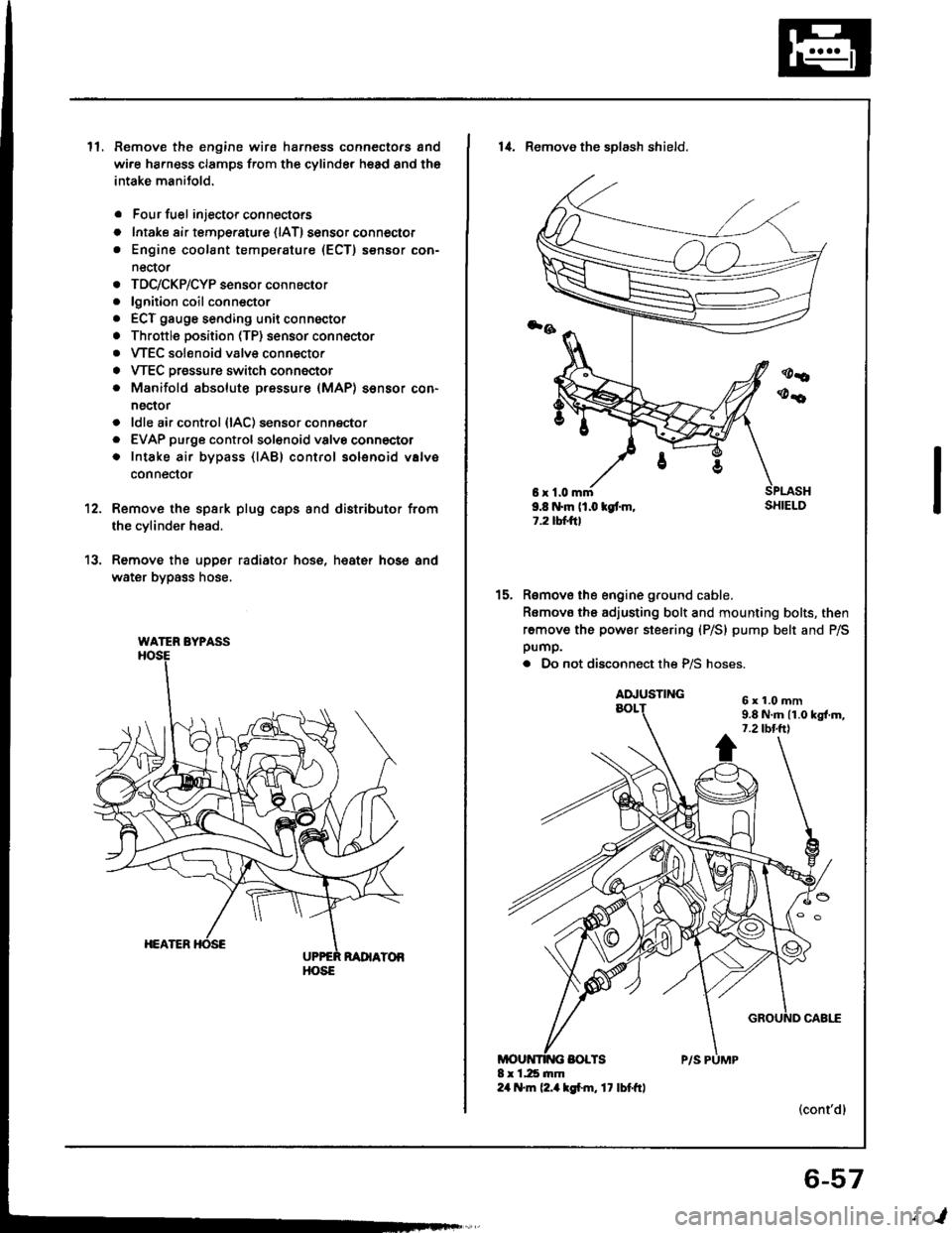
ll.Remove the engine wire harness connectors and
wi.e ha.ness clamps from the cylinder head and the
intake manitold.
Four fuel injector connectors
Intake air tempe.ature {lAT) sensor connector
Engine coolant temperature (ECT) sensor con-
nector
TDC/CKP/CYP sensor connector
lgnition coil conn€ctor
ECT gauge sending unit connector
Throttle position (TP) sensor connector
VTEC solenoid valve connector
VTEC Dressure switch connector
Manifold absolute pressure (MAP) sensor con-
nector
ldle air control {lAC) sensor connector
EVAP purge controlsol€noid valvo connector
Intake air bypass {lABl control solenoid valve
conneclor
a
o
a
o
a
a
a
a
a
a
a
a
a
12.
13.
Remove the spsrk plug caps and distributor from
the cylinder head.
Remove the upper radiator hose, heat€r hose and
water bypass hose.
WATER BYPASS
HOSE
6r1.0mm9.8 N.m (1.0 kgt m,1.2 tbtftl
14. Remove the sDlash shield.
Remove the engine ground cable.
Romovo the adjusting bolt and mounting bolts, then
remove the power steering (P/S) pump belt and P/Spump.
. Do not disconnect the P/S hoses.
(cont'dl
15.
6x1.0mm9.8 N.m 11.0 kgl.m,7.2 tbt.ttl
6-57
,l
Page 119 of 1413
Cylinder Head
Removal (cont'dl
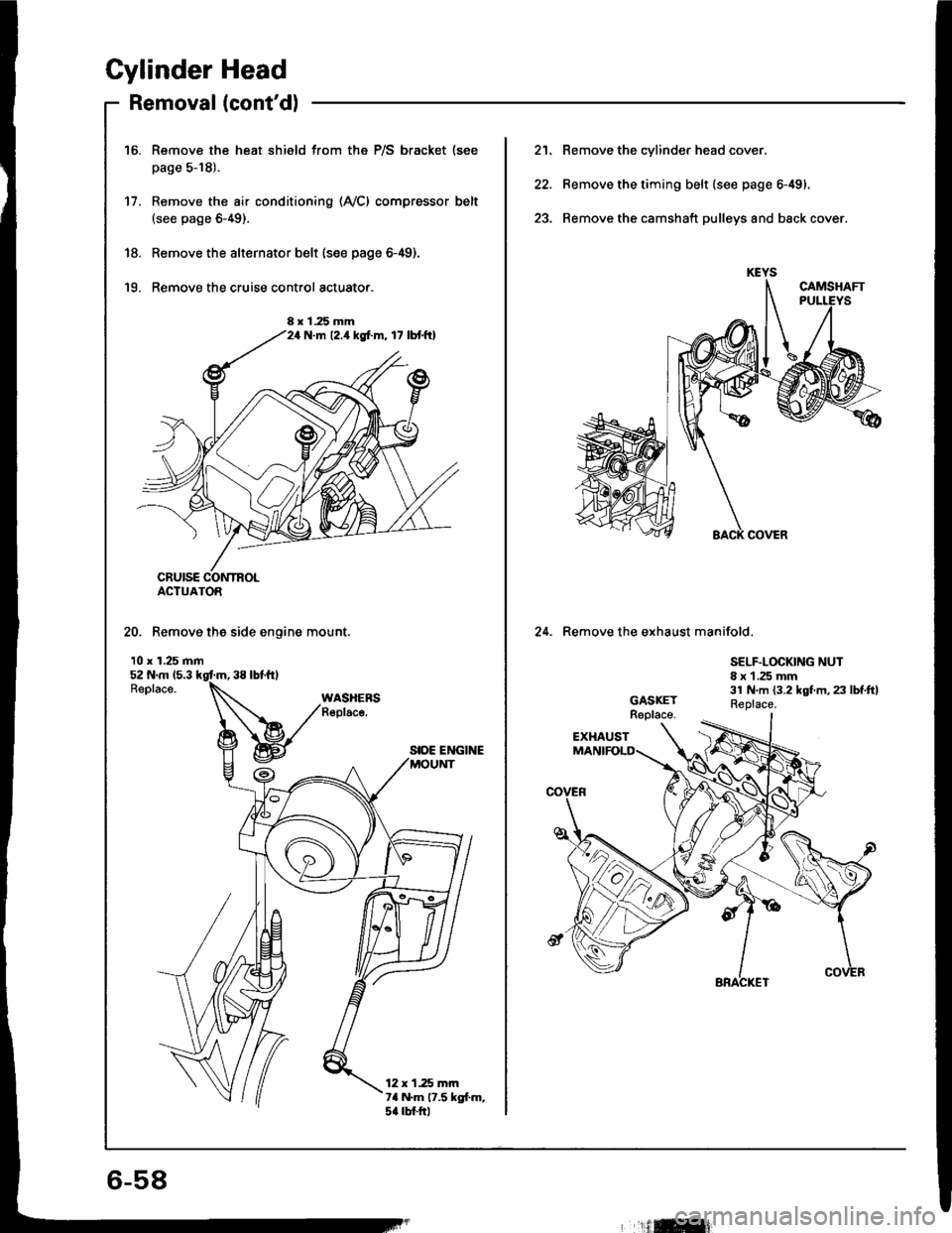
Remove the heat shield from the P/S bracket (see
page 5-18).
Remove the air conditioning (Ay'Cl compressor belt(see page 6-49).
Remove the alternator belt {s€e page 6-49).
Remove the cruise control actuato..
16.
17.
'18.
'19.
ACTUATOR
20. Remove the side engine mount.
10 x 1.25 mm
SIDE ENGINE
12 x 1.25 mrn7a N.m 17.5 kgl.m,5a rbtftl
8 x 1.25 mmN.m 12.4 kgf.m, 17 lbtftl
21. Remove the cylinder head cover.
22. Remove the timing belt (see page 6-49).
23. Remove the camshaft pulleys and back cover.
24. Remove the exhaust manifold.
SELF.LOCKING NUT8 x 1 .25 mm31 N.m {3.2 kgt m, 23 lbf.ftlReplace.
6-58
'ilffi{
Page 120 of 1413
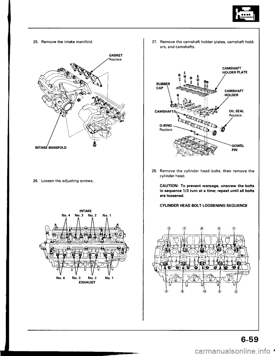
25. Remove the intake manifold.
26. Loosen the adjusting screws.
INTAKENo.4 No.3 No.2No. 1
No. 4No.3 No. 2EXHAUSTNo. 1
GASKET
21.Remove the camshaft holder plates, camshaft hold-
ers, and camshafts.
CAMSHAFT
28. Remove the cylinder head bolts, then remove the
cylinder head.
CAUTION: To prsvent warpage, unscrew th€ bolts
in sequence l/3 turn at a time; repeat until all bolts
aro loosoned.
CYLINDER HEAD BOLT LOOSENING SEOUENCE
6-59
Page 123 of 1413
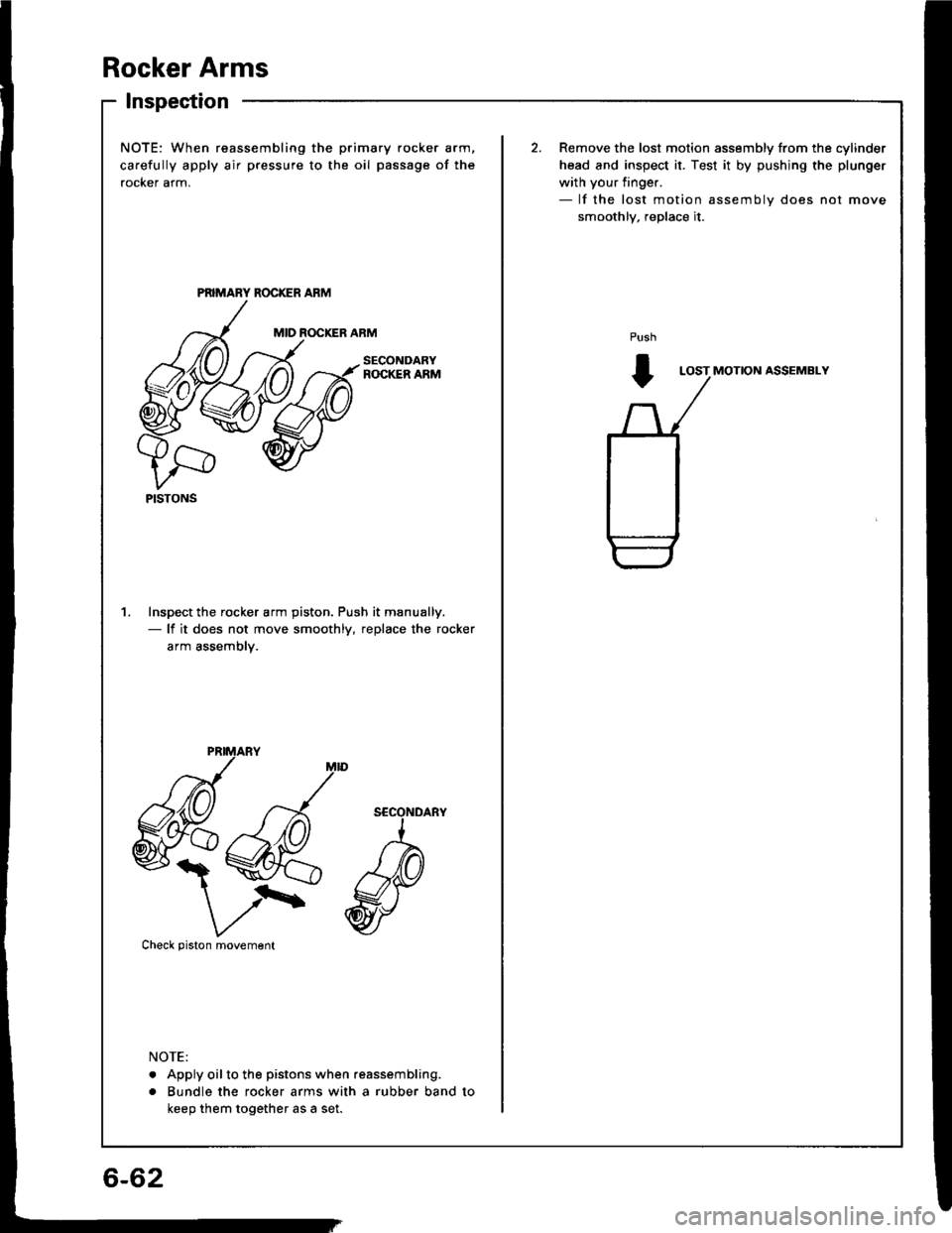
Rocker Arms
lnspection
NOTE: When reassembling the
carefully apply air pressure to t
rocker arm.
Inspect the rocker arm piston.- lf it does not move smoot
arm assembly.
xva
V/\'Check piston movement
. Apply oilto the pistons whe
. Bundle the rocker arms wi
keep them together as a set.
PISTONS
) primary rocker arm,
the oil passage of the
Remove the lost motion assembly from the cylinder
head and inspect it. Test it by pushjng the plunger
with your finger.- lf the lost motion assembly does not move
smoothlv, reDlace it.
ROCKER ARMPush
t
SECONDARYLOST MOTION ASSEMBLY
ciston. Push it manually.
smoothly, replace the rocker
when reassembling.
s with a rubber band to
6-62
Page 125 of 1413
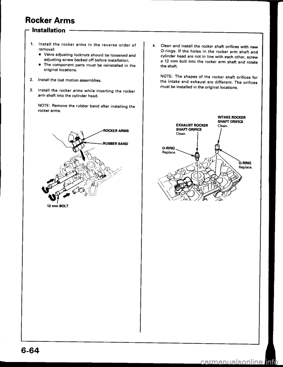
Rocker Arms
Installation
1. Install the rocker arms in the reverse order ofremoval:
. Valve adjusting locknuts should be loosened andadjusting screw backed off before installation.. The component parts must be reinstalted in theoriginal locations.
2. Installthe lost motion assemblies.
3. Install the rocker arms while insening the rockerarm shaft into the cvlinder head
NOTE: Remove the rubber band after installing therocKer arms.
'/'/
12 mm EOLT
4.Clean and install the rocker shaft orifices with newO-rings. lf the holes in the rocker arm shaft andcylinder head are not in line with each other, screwa 12 mm bolt into the rocker arm shaft and rotatethe shaft.
NOTE: The shapes of the rocker shaft orifices forthe intake and €xhaust are different. The orificesmust be installed in the original locations.
INTAKE ROCKERSHAFT ORIFICEClean.EXHAUST ROCKERSHAFT ORIFICECl6an.
O.RINGBeplace.
Beplace.
6-64
Page 126 of 1413
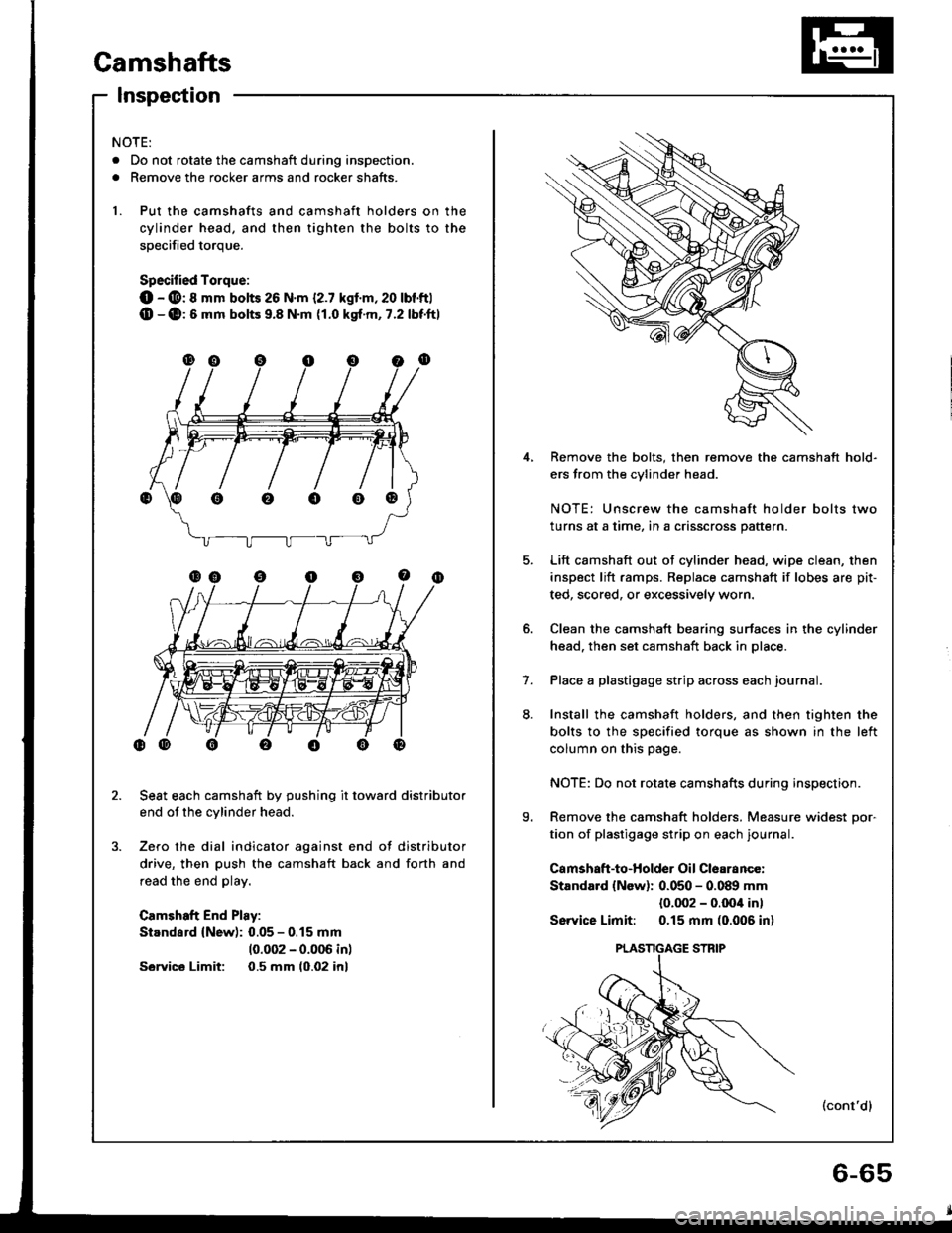
Camshafts
Inspection
4,
5.
9.
1.
Remove the bolts, then remove the camshaft hold-
ers from the cvlinder head.
NOTE: Unscrew the camshaft holder bolts two
turns at a time, in a crisscross pattern.
Lift camshaft out of cylinder head. wipe clean, then
inspect lift ramps. Replace camshaft if lobes are pit-
ted, scored, or excessively worn.
Clean the camshaft bearing surfaces in the cylinder
head. then set camshaft back in place.
Place a plastigage strip across each journal.
Install the camshaft holders, and then tighten the
bolts to the specified torque as shown in the left
column on this page.
NOTE: Do not rotate camshafts during inspection.
Remove the camshaft holders. Measure widest Dor-
tion of plastigage strip on each journal.
Camshaft-to-Holder Oil Clearance:
Standard {New): 0.050 - 0.089 mm
{0.002 - o.Ooil in)
Sswice Limit: 0.15 mm (0.006 in)
(cont'dl
NOTE:
. Do not rotate the camshaft during inspection.
. Remove the rocker arms and rocker shafts.
1. Put the camshafts and camshaft holders on the
cylinder head, and then tighten the bolts to the
soecified torque.
Specified Torque:
O - @: 8 mm bolts 26 N.m {2.7 kgl.m,20 lbt'ftl(D -(D:6 mm bolts 9.8 N.m {1.0 kgt.m, 7.2 lbf'ftl
Seat each camshaft by pushing it toward distributor
end of the cylinder head.
Zero the dial indicator against end of distributor
drive, then push the camshaft back and forth and
read the end play.
Camshaft End Play:
Standard (New): 0.05 - 0.15 mm
10.002 - 0.006 inl
Sawics Limit: 0.5 mm (0.02 inl
oooo@
Page 127 of 1413
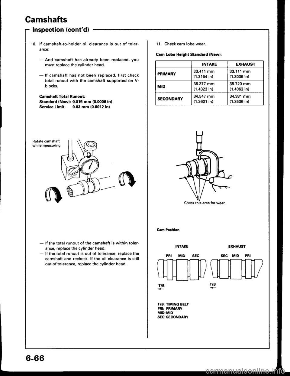
Gamshafts
Inspection (cont'd)
10, lf camshaft-to-holder oil clearance is out of loler-
ance:
- And camshaft has already been replaced, you
must replace the cylinder head.
- lf camshaft has not been replaced, first check
total runout with the camshaft supported on V-
blocks.
Camehaft Total Runout:
Sisndard (New): 0.015 mm (0.0006 inl
Service Limit: 0.03 mm (0.0012 in)
Rotat€ camshsftwhile measuring
- lf the total runout of the camshaft is within toler-
ance, replace the cylinder head.- lf the total runout is out of tolerance, r€Dlace the
camshaft and recheck. lf the oil clearance is still
out of tolerance. replace the cylinder head.
6-66
IiITAKEEXHAUST
PRIMARY33.i{'l1 mm
(1.3154 inl
33.111 mm(1.3036 in)
MID36.377 mm
l't.4322 inl
35.720 mm
(1.4063 inl
SECONDARY34.547 mm(1.3601 in)
34.381 mm(1.3536 in)
11. Check cam lobe wear.
Clm Lobs Hcight Standard (N.w):
Check this are6 tor wsar.
Crm Porition
INTAKE
MtosEc
CXHAUST
SEC MID PRI
fTt-]--Tt-Tt-l
\ll il il|/
tt ttlLIL__H___}{-}U
ftBftB
T/B: nMING BELTPRI: PRIMAFYMID: MIDSEC: SECONDARY
Page 131 of 1413
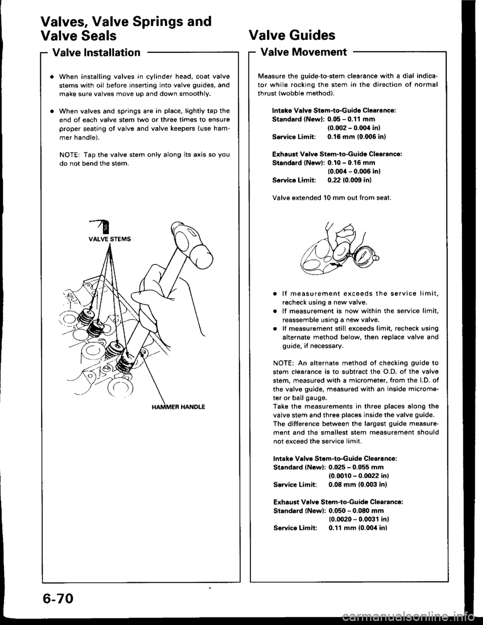
Valve lnstallation
When installing valves in cylinder head, coat valve
stems with oil before inserting into valve guides, and
make sure valves move up and down smoothly.
When valves and springs are in place, lightly tap the
end of each valve stem two or three times to ensure
proper seating of valve and valve keepers (use ham-
mer handle).
NOTE: Tap the valve stem only along its axis so you
do not bend the stem.
Valves, Valve Springs and
Valve SealsValve Guides
Valve Movement
Measure the guide-to-stem clearance with a dial indica-
tor while rocking the stem in the direction of normal
thrust (wobble method).
lntaks Valvr Stom-to-Guide Clearance:
Standard (Newl: 0.05 - 0.11 mm
{0.002 - 0.OO'l in)
Ssrvice Limit: 0.16 mm (0.006 in)
Exhaugt Vdve Stem-to-Guide Clsarancg:
Standald lNowl: 0.10 - 0.16 mm
(0.00'l - 0.006 in)
Sorvics Limit: 0.22 {0.0m in)
Valve extended 10 mm out from seat.
. lf measurement exceeds the service limit.
recheck using a new valve.
. lf measurement is now within the service limit,
reassemble using a new valve.
. lf measurement still exceeds limit, recheck using
alternate method below, then replace valve and
guide, if necessary.
NOTE: An alternate method ot checking guide to
stem clearance is to subtract the O.D. of the valve
stem. measured with a micrometer, from the l.D. ot
the valve guide, measured with an inside microme-
ter or ball gauge.
Take the measurements in three places along the
valve stem and three places inside the valve guide.
The difference between the largest guide measure'
ment and the smallest stem measurement should
not exceed the service limit.
lntafte Valvs Stom-to-Guida Clearance:
Stardard (Nowl: 0.025 - 0.055 mm(0.0010 - 0.0022 inl
Service Limit: 0.08 mm (0,003 in)
Exhaust Valvo Stem-to-Guide Clearance:
Standard lNew): 0.050 - 0.080 mm
10.0020 - 0.0031 in)
S€rvics Limit: 0.11 mm {0.0oil inl
6-70
Page 132 of 1413
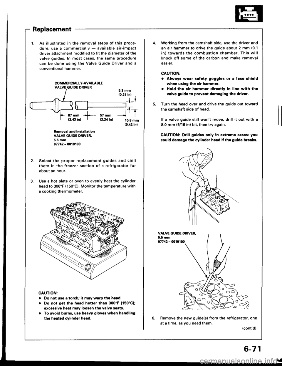
1.As illustrated in the removal steps ot this proce-
dure. use a commercially - available air-impact
driver attachment modified to fit the diameter of the
valve guides. In most cases, the same procedure
can be done using the Valve Guide Driver and a
conventional hammer,
COMMCRCIALLY.AVAILABLEVALVE GUIDE DRIVER
az mm +- sz mm{3.43 inl I tz.zt in)
tfr
10.8 mm10.42 inl
5.3 mm(0.21 inl I
_{l
R.mov.l and In3trll.tionVALVE GUIDE DRIVER.5.5 mm07742 - q)101tt0
Select the proper replacement guides and chill
them in the freezer section of a refrigerator for
about an hour.
Use a hot plate or oven to evenly heat the cylinder
head to 300'F (150"c). Monitor the temperature with
a cooking thermometer.
CAUTION:
. Do not us9 a iorch; it may warp ths hsad.
. Do not get ths head hottor than 300"F (150"C);
excsssivo hgat may loogen the valvo soaG.
. To avoid burns, use hsaw glovo3 whon handling
the heated cylindor h€ad.
Working from the camshaft side, use the driver and
an air hammer to drive the guide about 2 mm (0.1
in) towards the combustion chamber. This will
knock off some of the carbon and make removal
easier.
CAUTION:
. Always wear ssfcty gogglos 01 a taca rhiold
whcn using thc air hrmmcr,
. Hold tho.ir hammer diroctly in line with tho
v6lvo goido to prov.nt drmaging tho driv6r.
Turn the head over and drive the guide out toward
the camshaft side of head.
lf a valve guide still won't move, drill it out with a
8.0 mm (5/16 in) bit, then try again.
CAUTION; Drill guid6 only in oxtromc cs3os: you
could dlmsgo tho cylinder hoad if tho guidc brcakr.
VALVE GUIDE DBIVER.5.5 mm07742 - 0010100
6.Remove the new guide(s) from the refrigerator, one
at a time, as vou need them.(cont'd)
l o -_ -\
i oc)