check engine HONDA INTEGRA 1994 4.G Manual Online
[x] Cancel search | Manufacturer: HONDA, Model Year: 1994, Model line: INTEGRA, Model: HONDA INTEGRA 1994 4.GPages: 1413, PDF Size: 37.94 MB
Page 557 of 1413
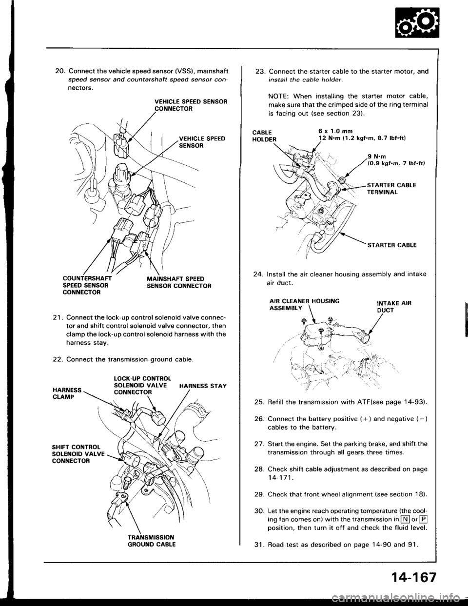
20. Connect the vehicle speed sensor (VSS), mainshatt
speed sensor and counterchalt speed sensor con
nectors.
VEHICLE SPEED SEiISORCONNECTOR
21. Connect the lock-uD control solenoid valve connec-
tor and shift control solenoid valve connector. then
clamp the lock-up control solenoid harness with the
harness stay.
22. Connect the transmission ground cable.
LOCK-UP CONTROLSOLENOID VALVE HARNESS STAY
23. Connect the starter cable to the starter motor, and
install the cable holder.
NOTE: When installing the starter motor cable,
make sure that the crimped side of the ring terminal
is facing out (see section 23).
CABLEHOLDER
6x 1.0 mm'12 N.m (1.2 kgf'm,8.7 lbt.tl)
24.
N.mlO.9 ksr.m, 7 tbr-rtt
STARTER CAELE
Install the air cleaner housing assembly and intake
arr oucl.
AIR CLEANER HOUSINGASSEMBLYINTAKE AIRDUCT
25.
26.
24.
29.
30.
Retill the transmission with ATF(see page '14-93).
Connect the battery positive ( + ) and negative ( - )
cables to the battery.
Start the engine. Set the parking brake, and shift the
transmission through all gears three times.
Check shitr cable adjustment as described on page
14-171 .
Check that front wheel alignment (see section 18).
Let the engine reach operating temperature (the cool-
ing tan comes on) with the transmission in S or @position, then turn it off and check the fluid level.
31. Road test as described on page 14-9o and 91.
14-167
Page 561 of 1413
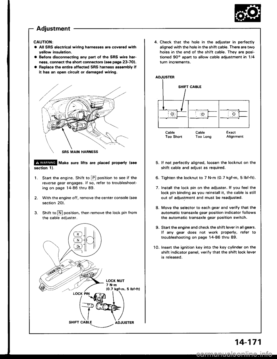
4. Check that the hole in the adiuste. in perfectly
aligned with the hole in the shift cable. There are two
holes in the end of the shitt cable, They are posi-
tioned 9Oo apart to allow cable adiustment in 1/4
lurn Incremenls.
ADJUSTER
CableI oo snonCableToo LongExactAlignment
5. It not perfectly aligned, loosen the locknut on the
shift cable and adjust as required.
6. Tighten the locknut to 7 N.m (O.7 kgf.m, 5lbf.ft).
7. Install the lock pin on the adiuster. lf you feel the
lock pin binding as you reinstall it, the cable is still
out of adjustment and must be readjusted.
8. Move the selector to each gear and verify that the
automatic transaxle gear position indicator tollows
the automatic transaxle gear position switch.
9. Start the engine and check the shift lever in all gea.s.
lf any gea. does not work properly, refer to
troubleshooting on page 14-86 thru 89.
1O. lnsert the ignition key into the key cylinder on the
shift indicator panel, ve.ify that the shift lock lever
is released,
CAUTION:
a All SRS electrical widng harn€sses are covar€d with
yollow insulation.
a Before disconnecting any part of ths SRS wire har-
ness, connect the shon connectors (see page 23-701.
a R€place the entire affected SRS halnass asssmbly it
it has an op€n circuit or damaged wiring.
@ tu"t" sure lifts a.e placed properly ls66
ssction 1).
Start the engine. Stritt to @ position to see if the
reverse gear engages. lf so, refer to troubleshoot-
ing on page 14-86 thru 89.
Wilh the engine off, remove the center console {see
section 20).
Shilt to N position. then remove the lock pin from
the cable adjuster.
'1.
/
''fidlfr
I
t+@
\/ \
CABLE-.'.-_--l../ADJUSTER
]H
@
@
@
Adjustment
14-171
Page 583 of 1413
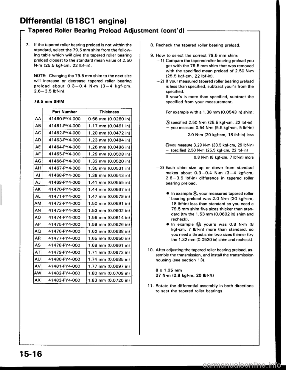
Differential (B18C1 enginel
Tapered Roller Bearing Preload Adjustment (cont'dl
7. It the tapered roller bearing preload is not within the
standard, select the 79.5 mm shim lrom the follow-
ing table which will give the tapered roller bea.ing
preload closest to the standard mean value of 2.50
N.m (25.5 kgJ.cm, 22 lbf.in).
NOTE: Changing the 79.5 mm shim to the next size
will increase or decrease tapered roller bearing
preload about O.3-O.4 N.m (3-4 kgf.cm,
2.6 - 3.5 lbt.in).
79.5 mm SHIM
Part NumbelThickness
41460-PY4-0000.66 mm (0.0260 in)
AB41461-PY4-0001.17 mm (O.0461In,
AC41462-PY4-0001 .2O mm (0.0472 in)
AD41463-PY4-0001.23 mm (O.O484 in)
AE41464-PY4-0001.26 mm (0.0496 in)
AF41465-PY4-OOO1.29 mm (O.O5O8 in)
AG41466-PY4-OOO1.32 mm (O.O52O in)
AH41 467-PY4-0001.35 mm {O.O531 in)
AI41468-PY4-0001.38 mm (O.O543 in)
AJ41469-PY4-0001 .41 mm (O.0555 in)
AK41470-PY4-OOO1 .44 mm (0.0567 in)
AL41 47 1 -PY 4-OOO1 .47 mm (0.0579 in)
AM41 47 2-PY 4-OOO1.50 mm {O.O591 in)
AN41473-PY4-0001 .53 mm (0.0602 in)
AO41 47 4-PY 4-OOO1.56 mm (0.0614 in)
AP41475-PY4-OOO'l .59 mm (O.0626 in)
AO4'1476-PY4-O001.62 mm (0.0638 in)
AR41 47 7 -PY 4-OOO1 .65 mm (0.0650 in)
AS41478-PY4-0001 .68 mm {0.0661 in)
41479-PY4-OOO1.71 mm (O.0673 in)
AU41480-PY4-OOO1.74 mm (0.0685 in)
41481-PY4-OOO1 .77 mm {0.0697 in}
41442-PY4-OOO1.80 mm (O.O7O9 in)
AX41483-PY4-OOO1.83 mm (0.0720 inl
15-16
9.
Recheck the tapered roller bearing preload.
How to select the correct 79.5 mm shim:- 1) Compare the tapered roller bearing preload you
get with the 79.5 mm shim that was removed
with the specified mean preload of 2.50 N.m(25.5 kgf .cm. 22 lbf.inl.-2) lf your measured tapered roller bearing preload
is less than specified, subtract your's from the
soecified.
lf your's is more than specified, subtract the
specified from your measurement.
For example with a 1 .38 mm (O.O543 in) shim:
@ specified 2.50 N.m (25.5 kgf.cm, 22 lbf.in)- you measure 0.54 N.m (5.5 kgt.cm, 5lbt'in)
2.0 N.m {20 kgf.cm, 18lbt.in} less
@you measure 3.29 N.m {33.5 kgl.cm, 29 lbl.in)- specified 2.50 N.m {25.5 kgf.cm, 22 lbf.in)
0.8 N.m (8 kgf.cm, 7lbt.in) more
3) Each shim size uD or down from standard
makes about O.3-O.4 N.m (3-4 kgf.cm,
2.6-3.5 lbf.in) difJerence in tapered roller
bearing preload.
a In example @, your measured tapered roller
bearing preload was 2.O N.m (20 kgf'cm,
I 8 lbl.in) less than standard so you need a
79.5 mm shim five sizes thicker thsn stan-
dard {trv the 1.53 mm (0.0602 inl shim and
recheck).
a In example @ your's was O.8 N.m (8
kgf.cm, 7 lbJ.in) more than standard, so
you need a thrust shim two sizes thinner (try
the 1.32 mm (0.0520 in) shim and recheck).
After adjusting the tapered .oller bearing preload, as-
semble the transmission, and installthe transmission
housing {see section 13).
8 x 1.25 mm
27 N.m 12.8 kgt.m. 20 lbf.ttl
Rotate the diJJerential assemblv in both directions
to seat the tapered roller bearings.
10.
11.
Page 617 of 1413
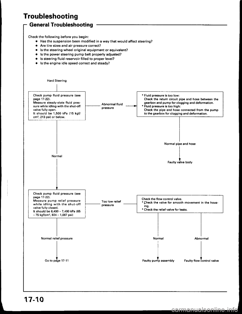
Troubleshooting
General Troubleshooting
Check the following betore you begin:
. Has the susp€nsion been modified in a way that would affect steering?. Are tire sizes and air pressure correct?
. ls the steering whe€l original squipment or equivalent?
. ls the power steering pump belt properly adiusted?
o ls steering fluid reservoir filled to proper level?
o ls the engine idle speed correct and steady?
Normal reliel pressure
I
I
Go to pate tu.l t
r Fluid pro$ure is too low:Chock th€ rgturn circuit pipe and hose between thogearbox and pump tor clogging and dotormation.* Fluid pressure is too hioh:Check the pipe and hosg connected from th6 pumpto tho georbox tor clogging and delormation.
Check pump fluid pressurg (soepage 17-221,Measure steady-state fluid pres-sure while idling with the shut-offvalve fully open.Ir shoutd be 1,500 kPa (15 kgtcm'�, 213 psi) or bolow.
Normal
Check pump fluid pr€ssur€ {se€page 17-221.Measure pump relief pressurewhile idling with the shut-offvalve fully closod.h should be 6,400 - 7,400 kPa {65- 75 kgtcm,, 924 - 1,067 psi)
Check the flow control valve.* Check lhe valve for smooth movement in thg hou6-Ing.* Chock thg reli€f valve for leaks.
Abnormal
I
I
Faulty flowtontroi valve
17-10
Page 618 of 1413
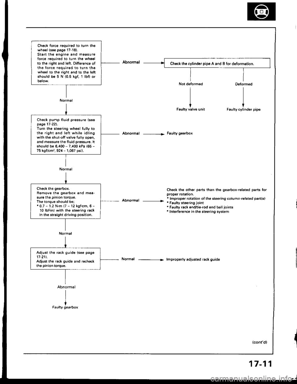
Ch6ck force r6quired to turn thowheel(see page 17-18).St6 the engine and m6asureforce required to turn the whgelto the right and left. Dilference olthe lo.ce required to turn thewho€l to the right and to the lettshould be 5 N (0.5 kgf, 1 lbf) orbelow.
Normal
Ch6ck pump fluid pressure (seepage 17-221.Turn the steering wheel lully tothe right and left whil€ idlingwith the shut-off valvo fully op6n,and measure tho fluid pressu.e. ltshould be 6,400 - 7,400 kPa (65 -
75 kg?cm,, 924 - 1,067 psil.
Normal
Abnormal -----|. Faulty gearbox
Abnormal |r
Chsck the other parts than the gearbox-ralated psrts forpropor rotstion,* lmpropor rotation ofthe steering column-rolat€d pan(sl'Faulty st6€ring jointa Faulty rack end^ie-rod end balljoints'Intederence in the steering system
lmproperly adjusted rack guide
(cont'dl
Chock the gearbox.Remove the goarbox and mea-sure the pinion torque.The torque should be;* 0.7 - 1.2 N.m (7 - 12 kgf.cm, 6 -'10 lbt in) with the steering rackin the straight driving position.
Normal
Adjust the rack guide (see page11-211.Adiust the rack guide and recheckthe pinion torque.
17-11
Page 621 of 1413
Troubleshooting
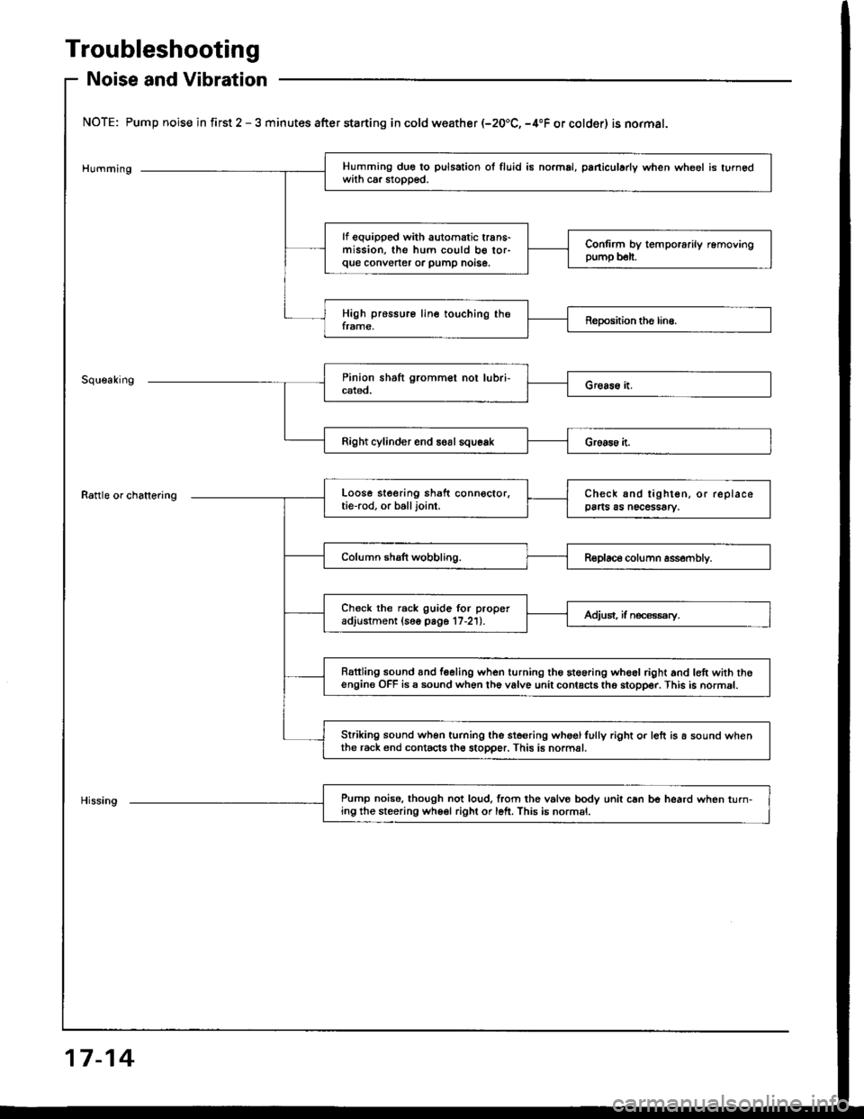
Noise and Vibration
NOTE: Pump noise in first 2 - 3 minutes after starting in cold weather (-20.C, -4"F or colder) is normal.
Humming
Rattle or chattering
Right cylinder end soal squeak
Pump noise. though not loud,lrom the vslvo bodv unit can be heard when turn-ing the steering wheel right or left. This is normsl.
Humming due to pulsation ol fluid is no.mal, paniculady when wheel is turnedwith ca. stopped.
lf equipped with automatic trans-mission, the hum could b€ tor-que convener or pump notse.
Confirm by temporarily removingpump b€lt.
High pressure line touching theframe,Reposhion tho line.
Loose steering shaft connector.tie-rod, or balljoint.Check and tighten, or replacepa s as necessary.
Column shaft wobbling.Replace column assembly.
Check the rack guide for properadjustment (16o page 17-21).Adjust, if n€ca€ssry.
Rattling sound and feeling when turning the steoring wheel right and lett with thoengine OFF is a sound when th6 valve unit contacts tho stopper. This is normal.
Striking sound wh6n turning the ste€ring whoglfully right o. left is a sound whenthe r6ck end contacts th6 stopper. This is normal.
17-14
Page 625 of 1413
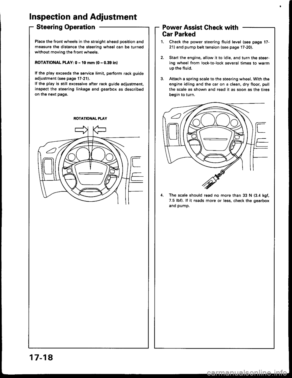
Place the front wheels in the straight ahesd position and
measure the distSnce the steering wheel can be turned
without moving the front wheels.
ROTATIONAL PLAY: 0 - 10 mm l0 - o.:Xl inl
lf the plsy excseds the service limit, psrform rack guide
adjustment (see page 17-211.
lf the play is still excessive after rack guide adjustment,
inspect the stsering linksgo and gearbox as described
on the next page.
ROTANONAL PLAY
Inspection and Adjustment
Steering OperationPower Assist Gheck with
817-1
Gar Parked
1. Check the power steering fluid level (see page 17-
21) and pump belt tension lsee page l7-20).
2.Start the engine, allow it to idle, and turn the steer-
ing wheel from lock-to-lock sev€ral times to warm
uo the fluid.
Attach a spring scale to the steering wheel. With the
engine idling and the car on a clean, dry floor, pull
the scale as shown and read it as soon 8s the tires
begin to turn,
il. The scal6 should read no more than 33 N (3.4 kgf,
7.5 lbf). lf it reads more or less, ch€ck the gearbox
and pump.
Page 628 of 1413
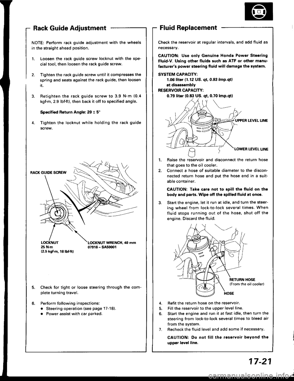
NOTE: Perform rack guide adjustment with the wheels
in the straight ahead position.
Loosen the rack guide screw locknut with the spe-
cialtool, then loosen the rack guide screw.
Tighten the rack guide screw until it compresses the
spring and seats against the .ack guide, then loosen
it.
Retighten the rack guide screw to 3.9 N.m {0.4
kgf'm, 2.9 lbf.ft), then back it off to specified angle.
Specified R6turn Angle: 20 t 5"
Tighten the locknut while holding the rack guide
screw.
1.
6.
RACK GUIDE SCREW
25 N.m12.5 kgf.m, 18lbtftl
L(rcKNUT WRENCH, 40 mm07916 - SAs(xtOl
Check for tight or loose steering through the com-
plete turning travel.
Perform following inspections:
. Steering operation (see page 17-18).
. Power assist with car parked.
Check the reservoir at regular intervals. and add fluid as
necessary.
GAUTION: Use only Genuine Honda Power Stosring
Fluid-V. Using othsr fluids such as ATF or other manu-
facturer's power stoering fluid will damags ths systcm,
SYSTEM CAPACITY:
LO6 litor (1.12 US. qt, 0.93 lmp.qtl
at disasssmbly
RESERVOIR CAPACITY:
0.79 lit6r (0.8:l US. qt, 0.70 lmp.qt)
UPPER LEVEL UNE
LOWER LEVEL LINE
,l
Raise the reservoir and disconnect the return hose
that goes to the oil cooler.
Connect a hose of suitable diameter to the discon-
nected return hose and put the hose end in a suit-
able container.
CAUTION: Tako caro not to 3pill tho tluid on tho
body and parts. Wipe off the spilled tluid at onqe.
Start the engine. let it run at idle. and turn the steer-
ing wheel from lock-to-lock several times. When
fluid stops running out of the hose, shut off the
engine. Discard the fluid,
Refit the return hose on the reservor.
Fill the reservoir to the uDoer level line.
Start the engine and run it at fast idle, then turn the
steering from lock-to-lock several times to bleed air
f.om the system.
Recheck the fluid level and add some if necessary.
CAUTION: Do not lill the roservoir beyond tho
uppgr lovel line.
7.
Page 629 of 1413
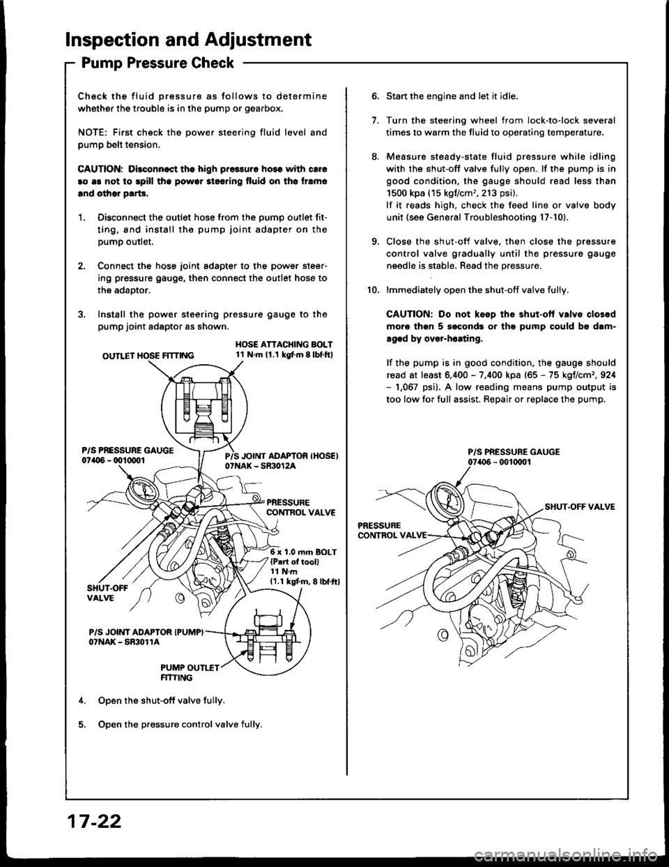
lnspection and Adjustment
Pump Pressure Check
Check the fluid pressure as follows to determine
whether the trouble is in the pump or gearbox.
NOTE: First check the power steering fluid level and
pump belt tension,
CAUnON: Dilconn€st the high pros3uro ho3s with cale
!o e3 not to spill tho powor stooring fluid on th6 lramo
lnd olhor parG.
1. Disconnect the outlet hose from the oumo outlet fit-
ting, 8nd install the pump joint adapter on the
pump outlet.
2, Connect the hose joint sdapter to the power steer-
ing pressure gauge, then connect the outlet hose to
the adaotor.
3. Instsll the power steering pressure gauge to the
pump joint adaptor as shown.
OUTLET HOSE FlTnNG
HOSE ATTACHING BOLT1l Nm11.1 kg{ m 8lbf.ftl
6 x 1.0 m.n BOLT{P!rt of tooll11 N.m11.1 kgtm,8lbf.ftl
P/S JOINT ADAPTOR IPUMPIo?NAK - SmolrA
PUMP OUTI.TTFITIING
Open the shut-off valve fully.
Open the pressure control valve fully.
17 -22
1.
Start the engine and let it idle.
Turn the stee.ing wheel from lock-to-lock several
times to warm the fluid to operating temperature.
Measure steady-state fluid pressure while idling
with the shut-off valve fully open. lf the pump is in
good condition, the gauge should read less than
1500 kpa (15 kgf/cm,,213 psi).
lf it reads high, check the feed line or valve body
unit (see General Troubleshooting l7-10).
Close the shut-off valve. then close the pressure
control valve gradually until the pressure gauge
needle is stabl6, Read the pressure.
lmmediately open the shut-off valve fully.
CAUTION: Do not keep the shut-ott valvs closod
moro thgn 5 soconds or th9 pump could b6 dam"
agod by over-h6ating,
lf the pump is in good condition, the gauge should
read at least 6.400 - 7,400 kpa (65 - 75 kgIlcm,,924- 1,067 psi). A low reading means pump output is
too low for full assist. Repair or replace the pump.
10.
P/S PRESSURE GAUGE
Page 651 of 1413
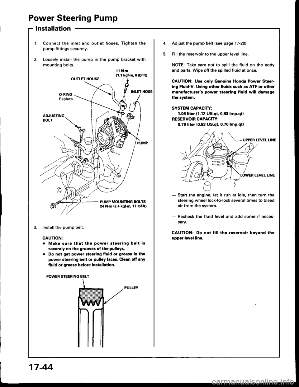
Power Steering Pump
lnstallation
1.Connect the inlet and outlet hoses. Tighten the
pump fiftings securely.
Loosely install the pump in the pump bracket with
mounting bolts.
11N.m11.r kgf.m, 8lbf.ftlOUTIIT HOUSE
INI.TT HOSEO-RINGReplaco.
ADJUSTINGBOLT
PUMP MOUNTING BOLTS2,r N.m {2.4 kgl.m. 17 lbf'ft}
Install the DumD belt.
CAUTION:
. Make surs that thg powor gtooring bslt i!
securgly on the grooyos of ths pulloy!.
. Do not get powor stggring fluid o. groaso in thg
power steering bclt or pulley trc6. Cloan oft 8ny
tluid or groa36 belore installation.
POWER STEERING BELT
PULI..EY
5.
Adjust the pump belt (see page 17-201.
Fill the reservoir to the uoDer level line.
NOTE; Take care not to spill the fluid on the body
and parts. Wipe off the spilled fluid at once.
GAUTION: Uro only Ganuino Honda Powor Stsor.
ing Fluid-V. Using othor tlui& 3uch a3 ATF or oiher
manutacturor's powor steering tluid will drm89e
the rystgm.
SYSTEM CAPACITY:
1.06litor (1.12 US.qt, 0.93 lmp.qt)
RESERVOIR CAPACIW:
0.79 litor (0.1|:| US.qt, 0.?0 lmp.qtl
UP?ER I.fVEL LINE
IEVEI LINE
- Start the engine, let it run at idle, then turn the
steering wheel lock-to-lock severaltimes to bleed
air from the system.
- Recheck the fluid level and add some if neces-
s8ry.
CAUTIONT Do not fill tha .63ervoir boyond th6
upp€r lcvol lino.
17 -44