check engine HONDA INTEGRA 1994 4.G Repair Manual
[x] Cancel search | Manufacturer: HONDA, Model Year: 1994, Model line: INTEGRA, Model: HONDA INTEGRA 1994 4.GPages: 1413, PDF Size: 37.94 MB
Page 319 of 1413
Emission Control System
SystemDescription
The emission control system includes a Three Way Cata-
lytic Convener (TWC), Positive Crankcase Ventilation(PCV) system and Evaporstive Emission {EVAP) Contfol
syst€m. The emission control system is designed to meet
federsl and stats emission standards.
Tailpipe Emission
Inspection
f!fifil oo nor amoro ou]rng rnr! Foacqurr. ^!op
any open flame away from yout wotk atca.
Start the engine. Hold the engine at 3,OOO rpm with
no load (A/T in @ or@ position, M/T in neutral) until
the radiator fan comes on, then let it idle,
Connect a tachometer.
Check and adiust the idle speed, if necessary (sss
page 1 1-95).
Warm up and calibrate the CO meter according to
the meter manutacturer's inst.uctions.
Check idle CO with the headlights, hester blower,
rear window defogger, cooling fan, and air condition-
er otf.
NOTE: (Canada) Pull the parking br8ke lever up.
Stan the engine, then check that the headlights are
off.
CO meter should indicate 0.1 maximum.
11-130
Page 327 of 1413
(From page 1 1-137)
lTo page 1 1-'l39)
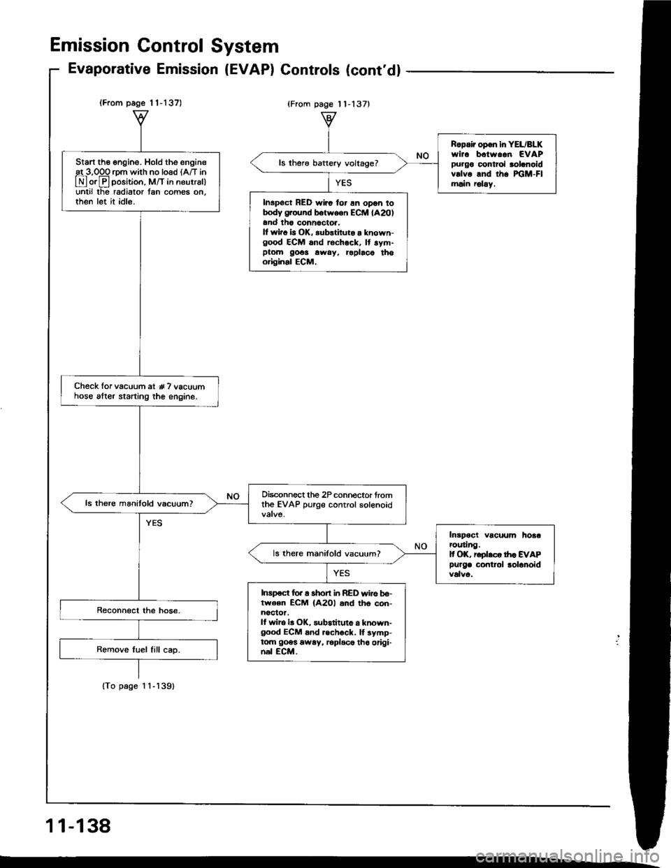
Start the engine. Hold the engineat 3,OOO rom with no load lA/T in
E orE position, M/T in neutrsl)unlil lhe radiator tan comes on.then let it idle.
Check lor vacuum at # 7 vacuumhose alter starting the engine.
Oisconnect the 2P connoctor fromthe EVAP purge control solenoid
Intpoct vacuum hoaarcuting.It OK, reolrco tr|c EVAP
Purge contlol lolanoid
ls there manifold vacuum?
Inrpoct for a short i|t RED wire bo-lwoen ECM {A2Ol and th6 con-noclor.ll wiro la OK, substituto a known-good ECM 6nd .echock. lf symp-tom goes away, loplace tho origi-nal ECM.
Ropair opon in YEL/BLKwirc b.tw..n EVAPpurgo control rolanoidvrlvo and th. xiM-Flmlin r6lay.
ls there baftery voltage?
Inspoct RED wirc for 6n opon totrody g.ound botween ECM lA20)and th6 conn6ctor.It wir. b OK, substiluto a known-good ECM and rochock, It sym-ptom 9o6s away, roplaco thooriginal ECM,
Emission Gontrol System
Evaporative Emission (EVAP) Gontrols (cont'd)
{From page 11-137}
11-138
Page 334 of 1413
Adjustment
NOTE:
a To check the clutch interlock switch and clutch
switch, see seclion 23.
a The clutch is selt-adjusting to compensate for wear.
CAUTION: It there is no clearanco between the mastel
cylinder piston and push lod. the releaso boaring is held
againsl the diaphragm spring, which can result in clutch
slippage 01 othel clutch problems.
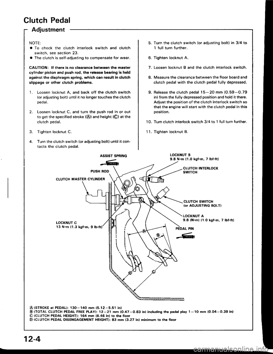
Loosen locknut A, and back otf the clutch switch
{or adjusting bolt) until it no longer touches the clutch
pedal.
Loosen locknut C, and turn the push rod in or out
to get the specified stroke (@) and height (O) at the
clutch pedal.
Tighten locknut C.
Turn the clutch switch (or adjusting bolt) until it con-
tacts the clutch pedal.
Turn the clutch switch (or adjusting bolt) in 3/4 to
1 full turn further.
Tighten locknur A.
7. Loosen locknut B and the clutch interlock switch.
8. Measure the clearance between the tloor board and
clutch pedal with the clutch pedal tully depressed.
9. Release the clutch pedal 15-20 mm {O.59-O.79
in) from the fully depressed position and hold it there.
Adiust the position of the clutch interlock switch so
that the engine will start with the clutch pedal in this
oosition.
1 0. Turn clutch interlock switch 3/4 to 1 tull turn funher.
11. Tighten locknut B.
LOCKNUT B9.8 N.m (1.0 kgf.m, 7 lbf.ftl
CLUTCH INTERLOCKswtrcH
6.
1.
2.
ASSIST SPRING
-6ll
LOCKNUT Cl3 N.m l'l.3 kgf.m, 9
CLUTCH SWITCH{or AOJUSTING BOLTI
LOCKNUT A9.8 {N.ml (1.0 kgl.m, 7 lbt.ftl
(STROKE at PEDALI: 130-140 mm 15.12-5.51 in){TOTAL CLUTCH PEDAL FREE PLAY): 12-21 mm 10.47-0.83 inl including tho p.dal play I -lO mm 10.04-0.39 inl{CLUTCH PEDAL HEIGHTI: 164 mm (6.46 in} to tho lloot{CLUTCH PEDAL DISENGAGEMENT HEIGHTI: 83 mm 13.27 inl minimum to tho lloo.
PUSH ROD
CLUTCH MASTER CYLINDER
Clutch Pedalctutch Pedat I
[-],ll'"-"" f
| :;i:'":fff*tr#:?iff:".,*::,::". | .#::J:::
sb''�'�'""
| |
| "orr,O", It there is no clearanco between the master | ,. aoo""n locknut B and the clutch intertoct switcl. | |cylinder piston and push lod. the releaso boaring is held | | Iagainst the diaphragm spring, which can result in clutch | 8. Measure tne clearance between the floor board and I Islippage 01 othel clutch problems.
I
clutch pedal with the clutch pedal tully deeressed.
I I1. Loosen locknut A, and back otf the clutch switch | 9. Release the clutch pedal 15-2O mm (O.59-O.79 I I
{or adiusting boltl until it no longer touches the clutch I int trom ttre fully depressed position and hold it there. I I
, ::":"" rocknut c, and rurn the push rod in or out | iliiiliffi:l1l:J"'1"-:H"l:tJ:i"i#fT: I I
. il*:*j':"'-(@)andheisht(olatthe
|
,:.;:,nterrockswitch3/4torrurrturnturtner.
I tf
,
::
***r**''
.,".,u"**;
|
'-"'"'';*1,,0*.,.-,.,*,
I I
Page 339 of 1413
InspectionReplacement
Flywheel, Flywheel Bearing
Inspect the ring gear teeth for wear and damage.
Inspect the clutch disc mating surface on the
flywheel fo. wear, cracks, and burning.
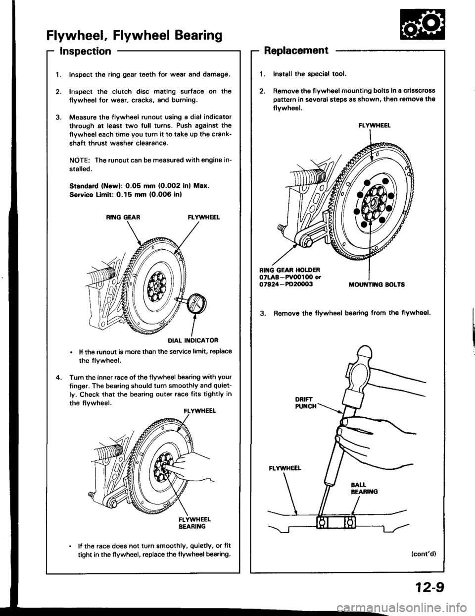
Measure the flywheel runout using a dial indicator
through at least two full tu.ns. Push against the
Ilywheel each time you turn it to take up the crank-
shaft thrust washe. clearance.
NOTE; The runout can be measu.ed with engine in-
stalled.
Standard (ttlervl: O.O5 mm (O.002 inl Max.
Service Limit: 0.15 mm 10.006 inl
RING GEABFLYWHEEL
DIAL II{DICATOR
It the runout is more than the service limit, leplace
the flvwheel.
Turn the inner race of the flywheel bearing with your
finger. The bearing should turn smoothly and quiet-
ly, Check that the bearing outer race fits tightly in
the flvwheel.
FLYWHEELBEARING
It the race does not turn smoothly, quietly, or fit
tight in the flywheel, replace the flywheel bearing.
Install the special tool.
Remov€ the flywhe€l mounting bolts in a criascross
pattern in several steps 8s shown, then remove the
tlywheel.
MOUI{TII{G BOLTS
3. Remov€ the flywheel bsaring from th€ tlywheel.
(cont'd)
FLYWHEEL
12-9
Page 345 of 1413
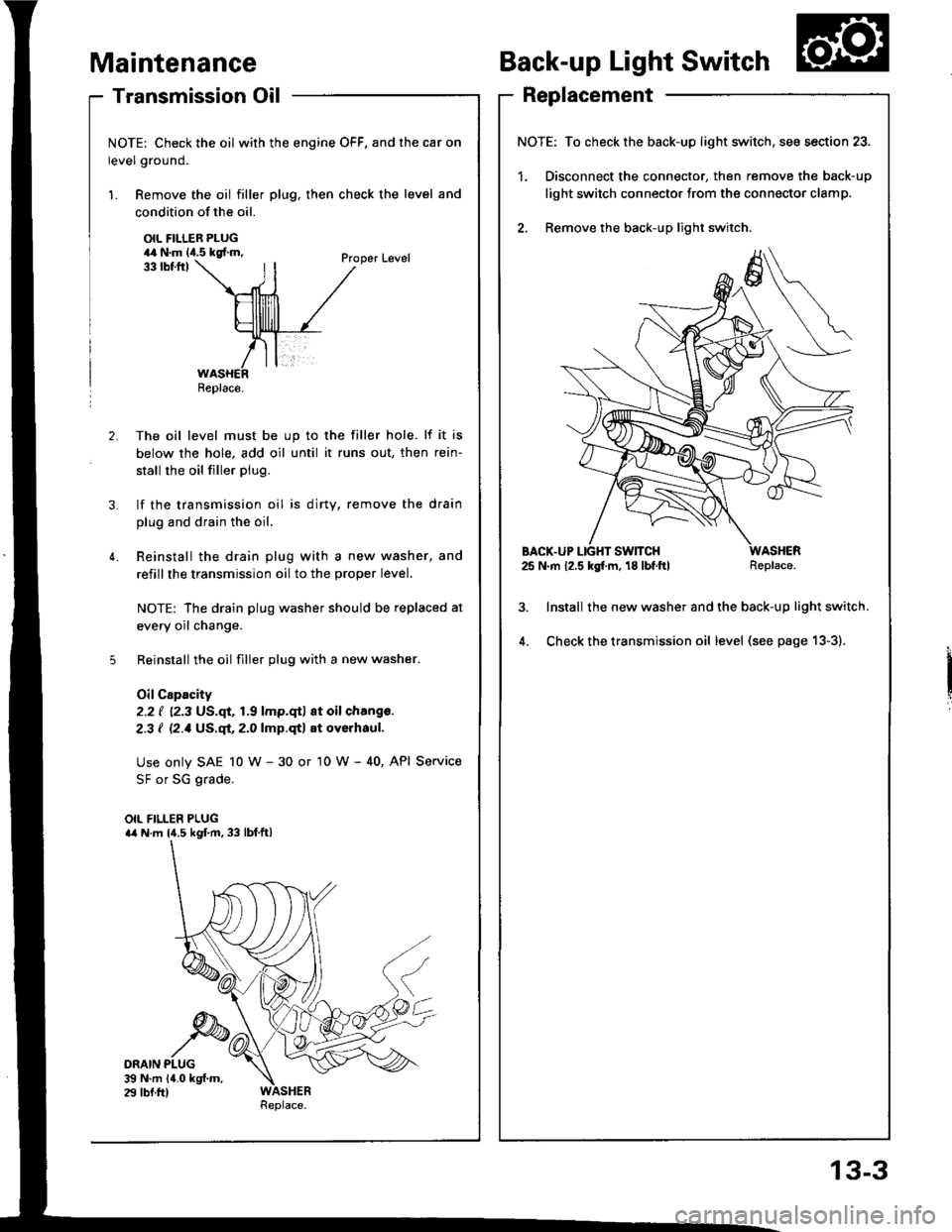
- Transmission Oil
NOTE: Check the oil with the engine OFF, and the car on
level ground.
1. Remove the oil filler plug, then check the level and
Maintenance
condition of the oil.
OIL FILLER PLUG44 N.m lia.5 kgf.m,
ORAIN PLUG$ N.m 14.0 kgf.m.29 lbf.fr)
33 tbtftlProper Level
2. The oil level must be up to the filler hole. lf it is
below the hole. add oil until it runs out, then rein-
stall rhe oil filler plug.
3. lf the transmission oil is dirty, remove the drain
plug and drain the oil.
4. Reinstall the drain plug with a new washer, and
refillthe transmission oil to the proper level.
NOTE: The drain plug washer should be replaced at
every oil change.
5 Reinstall the oil filler plug with a new washer.
OilCapacity
2.2 ( ''2.3 US.qt,1.9 lmp.qt) at oil chang€.
2-3 I l2.1Us.ql,2.0lmp.qtl at oyerhaul.
Use only SAE 10 w - 30 or '10 W - 40, API Service
SF or SG grade.
OIL FILLER PLUGa4 N.m l{.5 kgf.m, 33 lbf.ftl
Back-up Light Switch
Replacement
NOTE: To check the back-up light switch,
1. Disconnect the connector, then rem(
light switch connector trom the conn
2. Remove the back-up light switch.
BACX-UP LIGHT SWITCH25 N.m 12.5 kg[.m, 18 lbf.ftl
lnstall the new washer and the back-
Check the transmission oil level (see
Replace.
/itch, see section 23.
remove the back-up
]onnector clamp.
-up light switch.
) page 13-3).
Replace.
13-3
Page 369 of 1413
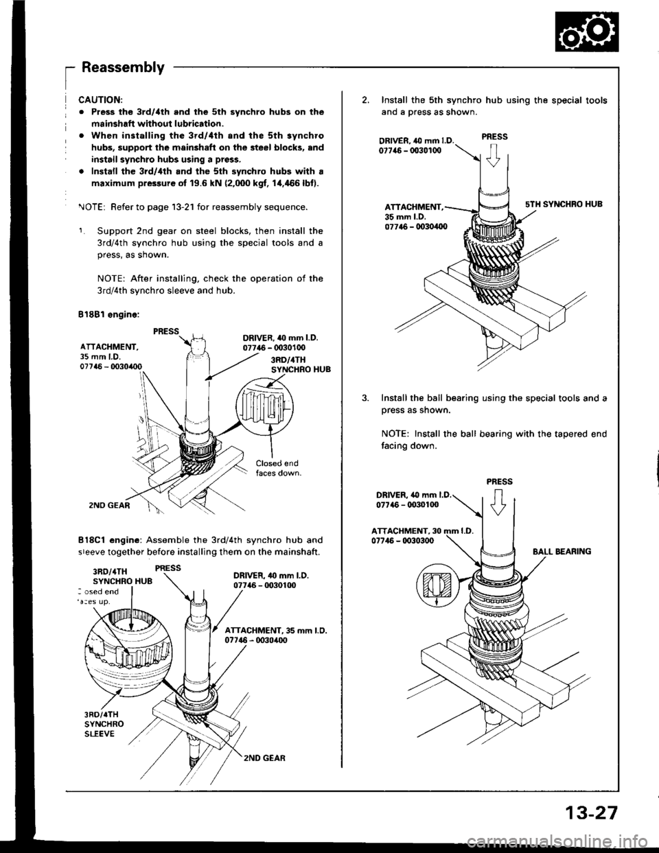
1_
ReassemblV
ATTACHMENT,35 mm LD.07746 - 0o30/rc0
CAUTION:
o Pless the 3rd/ilth and the 5th synchro hubs on the
msinshafi without lubrication.
. When installing the 3rd/4th and the sth synchro
hubs, support the mainshaft on the steel blocks, and
install synchro hubs using a press,
. Install the 3rd/,lth and the sth synchro hubs with a
maximum pressure of 19.6 kN (2.000 kgf, 1+466lbt).
^JOTEi Refer to page 13-21 for reassembly sequence.
Support 2nd gear on steel blocks, then install the
3rd/4th synchro hub using the special tools and a
press, as shown.
NOTE: After installing, check the operation of the
3rd/4th synchro sleeve and hub.
B18Bl sngine:
DRIVER. 40 mm l.D.07746 - 0030100
3RD/4THSYNCHRO HUB
2NO GEAR
8l8Cl engine: Assemble the 3rd/4th synchro hub and
sreeve together before installing them on the mainshaft.
3RO/4TH PRESS
SYNCHRO HU8DRIVER- 4o mm l.D.07746 - tD30100: osed end
3RD/TTHSYNCHROSLEEVE
2, Install the sth synchro
ano a press as snown.
OBIVER, ,O mm LD.0t7it6 - 003010O
ATTACHMENT,35 mm l.D.
hub using the special tools
PRESS
sTH SYNCHRO HUB
077t6 - 00304{x)
Install the ball bearing using the special tools and a
prsss as shown.
NOTE: Install the ball bearing with the tapered end
facing down.
2ND GEAR
13-27
Page 384 of 1413
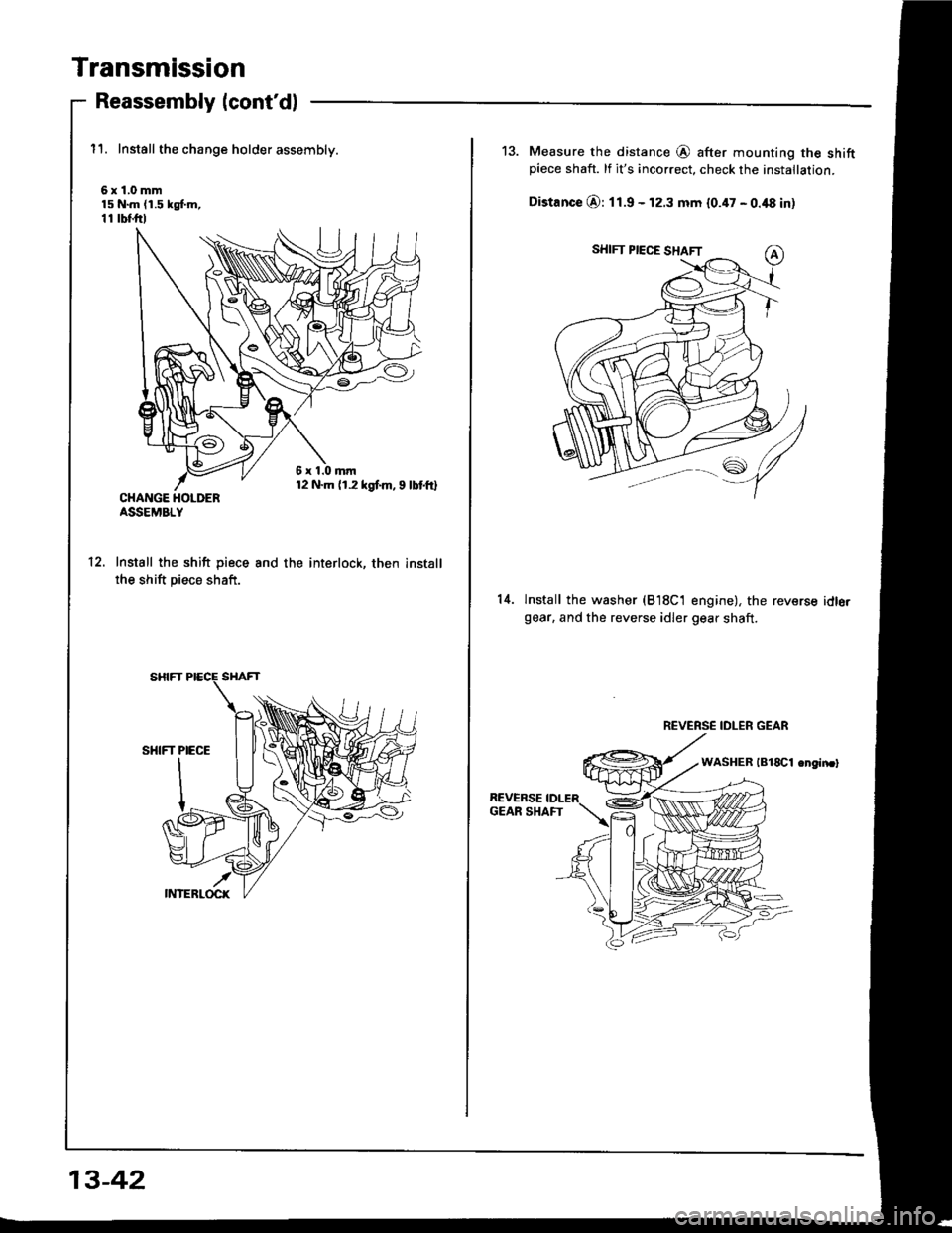
Transmission
Reassembly (cont'd)
11. Install the change holder assembly.
6x1.0mm15 N.m (1.5 kgf.m,11 tbf.ftl
CHANGE HOLDERASSEMBLY
Install the shift piece
the shift piece shaft.
and the interlock, then install12.
13-42
13. Measure the distance @ after mounting the shiftpiece shaft. lf it's incorrect, check the installation.
Distance O: 11.9 - 12.3 mm 10.47 - 0.48 in)
14.lnstall the washer (B18C1 engine), the reversegear. and the reverse idler gear shaft.
idlo.
REVERSE IDLER GEAR
Page 388 of 1413
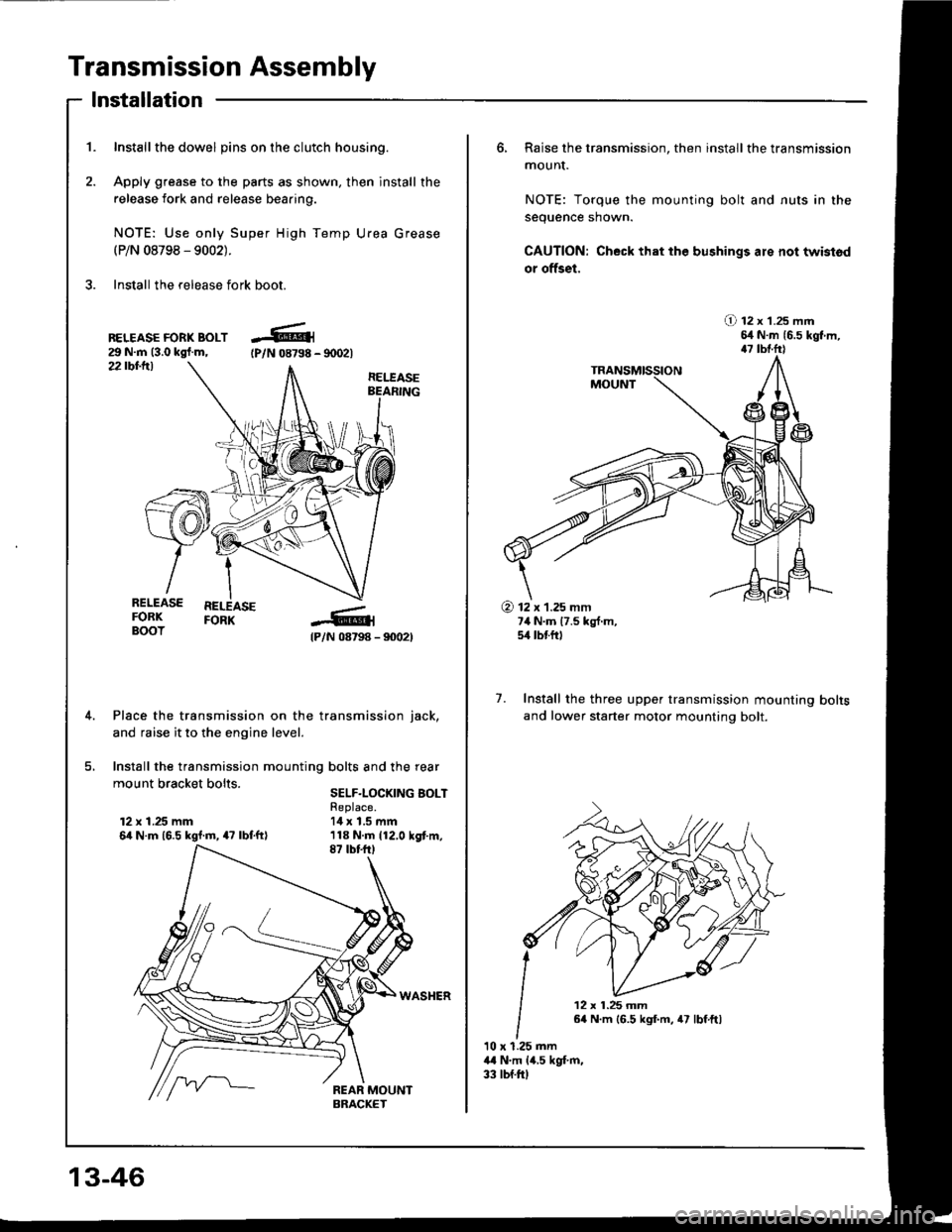
Transmission Assembly
1. Inst€llthe dowel pins on the clutch housing.
2. Apply grease to the parts as shown, then install the
release fork and release beaaing.
NOTE: Use only Super High Temp Urea Grease(P/N 08798 - 9002).
3. Install the release fork boot.
lnstallation
22 tbt-ttl
BELEASE FORK BOLT29 N.m (3.0 kgl.m,tPlN 08798 - 90021
RELEASEBEARING
@
I
{P/N 08798 - 90021
Place the transmission on the transmission iack,
and raise it to the engine level.
Install the transmission mounting bolts and the rear
mount bracket bolts sELF-LocKrNG BoLT
RELEASE REEASEFORK FORKBOOT
12 x 1.25 mm6it N.m 16.5 kgl.m, 47 lbf.ftl
Replace.14 x 1.5 mm
13-46
6, Raise the transmission, then install the transmission
mounI.
NOTE: Torque the mounting bolt and nuts in the
sequence shown.
CAUTION: Check that the bushings are not twistod
or offset,
O 12 x 1.25 mm54 N.m {6.5 kgt m,47 tbtfrl
7. Install the three upper transmission mounting
and lower starter motor mounting bolt.
bolts
10 x 1.25 mm44 N.m lil,s kgt m,33 tbf.ftl
@ 12 x 1.25 mm7,1 N.m 17.5 kg{.m,5/r lbtftl
12 x 1.25 mm64 N.m 16.5 kgf.m, 47 lbf.ftl
Page 395 of 1413
The Automatic Transmission is a combination of a 3-e,ement torque convefter and triple-shaft electfonically controlled
automatic transmission which provides 4 speeds forward and 1 speed reverse. The entire unit is positioned in line with
the engine.
Torque Converter, Gears and Clutches
The torque converter consists of a pump, turbine and stator assembly in a single unit, The torque converter is connected
to the engine crankshaft so they turn together as a unit as the engine turns. Around the outside of the torque converter
is a ring gear which meshes with the starter pinion when the engine is being staned. The entire torque converter assem-
bly serves as a flywheel while transmitting power to the transmission mainshaft.
The transmission has three parallel shafts, the mainshaft. countershaft and sub-shaft. The mainshatt is in line with the
engine crankshaft.
The mainshaft includes the clutches for 1 st, and 2ndl4th, and gears for 3rd. 2nd, 4th, reverse and l st (3rd gear is in-
tegral with the mainshaft, while reverse gear is integral with the 4th gear).
The countershaft includes the 3rd clutch and gears Ior 3rd, 2nd,4th, reverse, lst and parking. Reverse and 4th gears
can be locked to the countershaft at its center, providing 4th gear or reverse, depending on which way the selector is moved.
The sub-shaft includes the lst-hold clutch and gears for 1st and 4th
The gears on the mainshait are in constant mesh with those on the countershaft and sub-shaft. When certain combina-
tions of gears in the transmission are engaged by the clutches, power is transmitted from the mainshaft to the counter-
shaft via the sub-shatt to provide @, E, tr. tr and @ position.
Electronic Control
The electronic control system consists of the Transmission Control Module {TCM), sensors, and 4 solenoid valves. Shift-
ing and lock-up are electronically controlled for comfortable driving under all conditions.
The TCM is located below the dashboard, behind the left side kick panel on the driver's side.
Hydraulic Control
The valve bodies include the main valve body, secondary valve body, regulator valve body. servo body, and lock-up valve
body throuqh the respective separator plates.
They are bolted on the torque converter housing.
The main valve body contains the manual valve, 1-2 shift valve, 2-3 shift valve, Clutch Pressure Cont.ol (CPC) valve,
4th exhaust valve, relief valve, and oil pump gears.
The secondary valve body contains the 4-3 kick-down valve,3-2 kick-down valve,2-3 orifice cont.ol valve, 3-4 shitt
valve, orifice control valve. modulator valve, and servo control valve
The regulator valve body contains the pressure regulator valve. lock-up control valve, torque converter check valve, and
cooler check valve.
The servo bodv contains the servo valve which is integrated with the reverse shift fork, throttle valve B, and accumulators.
The lock-ug valve bodv contains the lock-up shift valve and lock-up timing B valve. and is bolted on the secondary valve
body.
Fluid from the regulator passes through the manual valve to the various control valves.
Shitt Control Mochanism
Input to the TCM i.om various sensors located throughout the car determines which shift control solenoid valve should
be activated.
Activating a shift control solenoid valve changes modulator pressure, causing a shift valve to move. This pressurizes
a line to one of the clutches. engaging that clutch and its corresponding gear.
Lock-up Mechanism
In @ position. in 2nd, 3rd and 4th, and E position in 3rd, pressurized tluid can be drained from the back of the tor-
que converter through an oil passage, causing the lock-up piston to be held against the torque converter cover. As this
takes Dlace, the mainshaft rotates at the same speed as the engine crankshatt. Together with hydraulic control, the TCM
optimizes the timing ol the lock-up mechanism.
The lock-up valves control the range of lock-up according to lock-up control solenoid valves A and B, and throttle valve B
When lock-up control solenoid valves A and B activate, modulator pressure changes. Lock-up control solenoid valves
A and B are mounted on the torque converter housing, and are controlled by the TCM.
(cont'd)
14-3
Page 421 of 1413
E Position
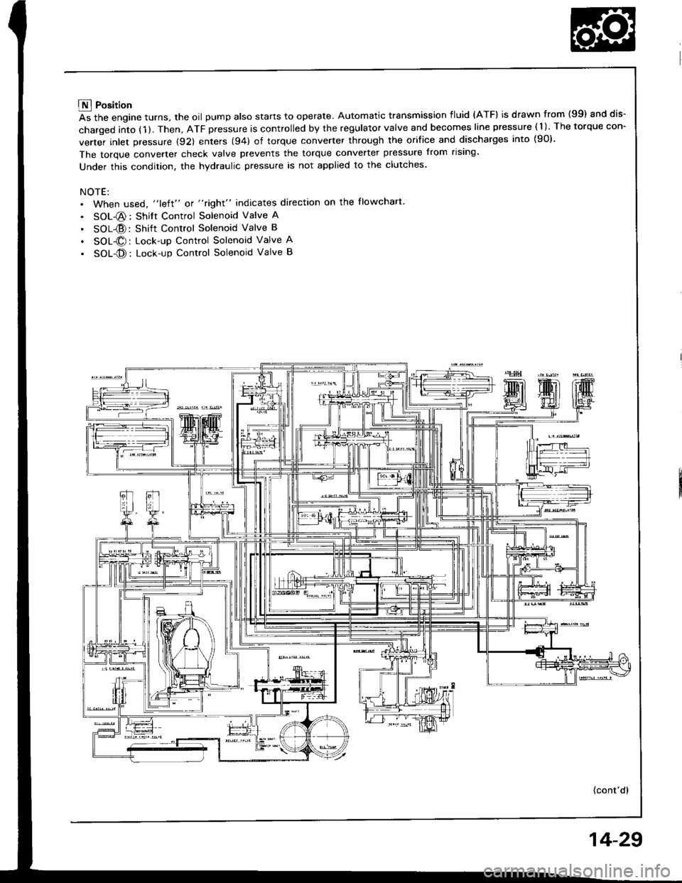
As the engine turns, the oil pump also starts to operate. Automatic transmission fluid (ATF) is drawn from (99) and dis-
charged into (1 ). Then, ATF pressure is controlled by the regulator valve and becomes line pressure ( 1 ). The torque con-
verter inlet pressure (92) enters (94) of torque converter through the orifice and discharges into {90}.
The torque converter check valve prevents the torque converter pressure from rising'
Under this condition, the hydraulic pressure is not applied to the clutches.
NOTE:. When used, "left" or "right" indicates direction on the llowchart
. SOL-@: Shift Control Solenoid Valve A
' SOL{D:Shift Control Solenoid Valve B
. SOL@: Lock-up Control Solenoid Valve A
. SOL-@: Lock-up Control Solenoid Valve B
(cont'd)
14-29