Idle HONDA INTEGRA 1994 4.G Workshop Manual
[x] Cancel search | Manufacturer: HONDA, Model Year: 1994, Model line: INTEGRA, Model: HONDA INTEGRA 1994 4.GPages: 1413, PDF Size: 37.94 MB
Page 24 of 1413
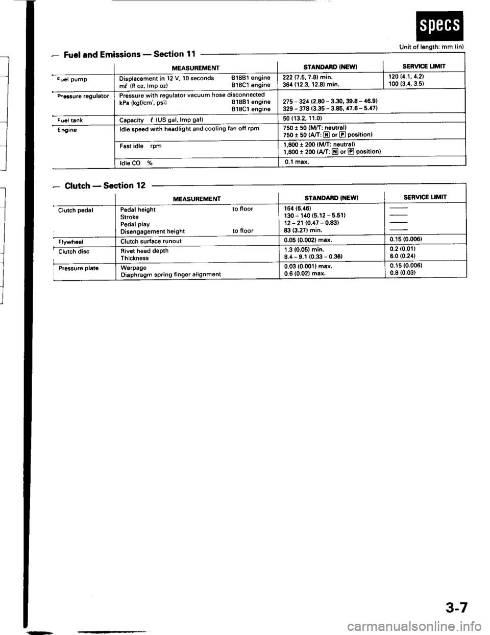
Fuel and EmissionsSection 11
ClutchSection 12
Unit ot length: mm {in)
MEASUREMENTsTAt{ItAno (NewlSERVICE UMIT
.u.l pumpDisolacoment in l2 V, 10 seconds 81881 engine
m, (fl oz, lmp oz) 818C1 engins222 17 .5,7 -81 min. | 12011.1' 1'21
364 (12.3, 12.8) min. I too (:.1, g.st
F aa3uro rggulatorPressure with regulator vacuum hose disconnected
kPa (kgflcm', psi) Bl8Bl engineBl8Cl engin€275 - 32a 12.8 -3.9,39.6 - 46.9)329 - 378 (3.35 - 3.85, 47.6- 5.47)
tualt6nkCaprcity, {US gal, lmp gal)50 (13.2, 11.01
En9in6ldle sDeed with headlight and cooling fan ofi rpm7501 50 (M/T: neut..ll750I 50 {A/T: E or E position}
Fast idle rpm1,600 i 2(x' lM/T: nsurr6l)l,eoo I 200 (A/T: E or E po6itioo)
ldl6 CO %0.1 max.
MEASUREMENTSTAM'Ad' IiEWISERVICE UMIT
clutch padslP6d6l height to lloor
SirokePedal play
Disengagement height to floor
164 (6.46)
130 - 140 (5.12 - 5.51)12 - 21 (0.47 - 0.83)83 (3.27) min.
Clutch sudace runout0.05 10.002) max,0.'15 (0.006t
clutch discRiv€t h€ad depthThickness
1.3 (0.05) min.8.4- 9.1 (0.3 - 0.36)0.2 (0.011
6.0 (0.24)
Pr6sur6 plat€WarpageOiaphragm spring linger alignment0.03 (0.001) mrx.0-6 (0.02) ma*0.15 (0.006)
0.8 (0.03)
{n+
3-7
Page 26 of 1413
MEASUREMENISTANDARD INEW)SERVICE LIMIT
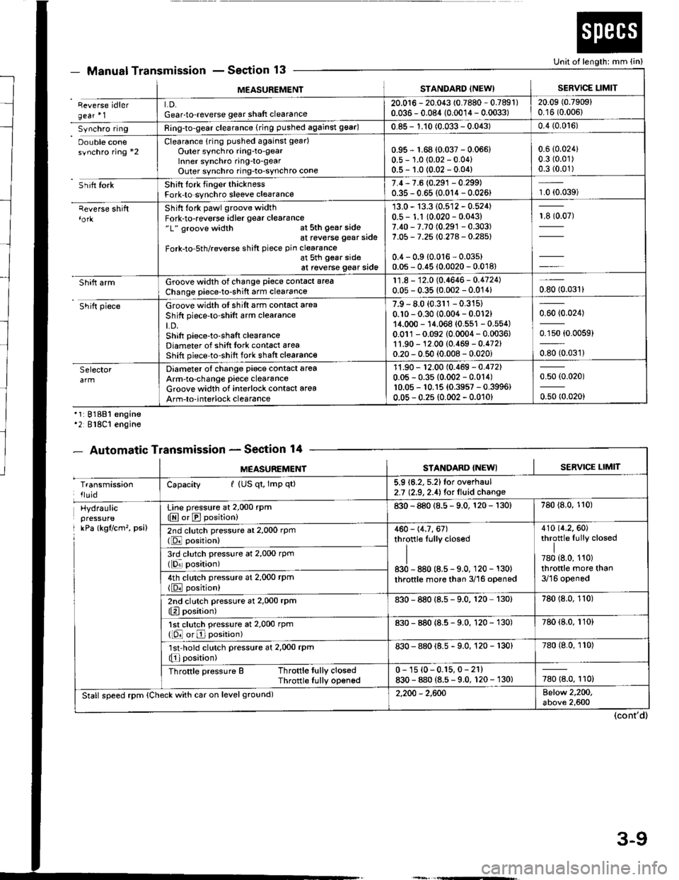
Reverse idlergear'1LD.Gear-to-reverse gear shaft clearance20.016 - 20.043 (0.7880 - 0.7891)0.036 - 0.084 (0.0014 - 0.0033)20.09 (0.7909)
0.16 (0.006)
Synchro ringRing-to-gear clearance (ring pushed against 99ar)0.85 - 1.10 (0.033 - 0.043)0.4 (0.0't6)
Oouble conesynchro ring *2Clearance {rin9 pushed against gear)
Outer synchro ring-to-gearlnner synchro ring-to-gearOuter synchro ring-to-synchro cone
0.95 r 1.68 (0.037 - 0.066)0.5 - 1.0 (0.02 - 0.04)0.5- 1.0 {0.02 -0.04)
0.6 (0.024)
0.3 (0.01)
0.3 (0.01)
Sh itt forkShift tork finger thicknessFork-to synchro sleeve clearance7.4,7.6 (0.291 - 0.299)0.35 - 0.65 (0.014 - 0.026)1.0 (0.039)
qeverse shiftShift fork pawl groove widthFork-to-reverse idler gear clearance"1" groove width at sth gear sideat reverse gear side
Fork-to-5th/reverse shift piece pin clearanceat 5th gear sideat reverse gear side
13.0 - 13.3 (0.512 - 0.524)0.5 - 1.1 10.020 - 0.043)7.40 - 7.70 (0.291 -0.303)
7.05 - 7.25 (0.278 - 0.28s)
0.4 - 0.9 {0.016 - 0.03s)0.05 - 0.45 (0.0020 - 0.018)
13907)
Shift armGroove width of change piece contact area
Change piece-to-shift arm clearance11.8 - 12.0 (0.4646- 0.4724)0.05 - 0.35 (0.002 - 0.014)0.8010.031)
Shift pieceGroove width of shift arm contact area
Shift piece'to-shift arm clearanceLD.Shift piece-to-shaft clearanceDiameter of shift Iork cont6ct areaShift piece-to-shift fork shaft clearance
7.9 - 8.0 (0.311 -0.315)
0.10 - 0.30 (0.004 - 0.012)14.000 - 14.068 {0.551 - 0.554)0.011-0.092 (0.0004 - 0.0036,1'1.90 - 12.00 (0.469 - 0.472)0.20 - 0.50 (0.008 - 0.020i
0.60 (0.024)
0.150 (0.0059)
oso to.oart
SelectorDiameter of change piece contact areaArm-to-change piece clearanceGroove widlh of interlock contact area
Arm-to-interlock clearance
11.90 - '�t2.00 (0.469 - 0.472)0.05 - 0.35 {0.002 - 0.014)10.05 - 10.15 {0.3957 - 0.3996}0.05 - 0.2s (0.002 - 0.010)
0.50 (0.020)
0.50 (0.020)
Manual TransmissionSection 13
'1:81881 engine'2 818C1 engine
- Automatic TransmissionSection 14
Unit of length: mm (in)
(cont'd)
- oEutrlrrl rr
MEASUREMENTSTANDARD {NEWISERVICE LIMIT
TransmissionlluidCapacity I (US qt, lmp qt)5.9 16.2, 5.2)for overhaul2.7 (2.9, 2.4) for lluid change
Hydraulicpressure
I kPa lkgflcm'�, psi)
Line pressure at 2,000 rpm(E or E position)830 - 880 (8.5 - 9.0, 120 - 130)780 {8.0, 110)
2nd clutch pressure at 2,000 rpm(DJ position)460 - 14.7, 67)throttle Iully closed
II830 - 880 (8.5 - 9.0, 120 - 130)
throttle more than 3/16 opened
410 {4.2.60)throttle fully closed
I780 {8.0, 110)throttle more than3/16 opened
3rd clutch pressure at 2,000 rpm(lqr posirion)
4th clutch pressure at 2,000 rPm
{E position)
2nd clutch pressure at 2,000 rPm(Elposition)830 - 880 {8.s - 9.0. 120 130)780 (8.0, 110)
1st clutch pressure at 2,000 rpm([O or E position)830 - 880 (8.5 - 9.0, 120 - 130)780 (8.0, 110)
'lst'hold clutch pressure at 2,000 rpm(Elposition)830 - 880 {8.5 - 9.0, 120 - 130}780 (8.0, 110)
Throttle pressure B Throttle fully closedThrotlle Iully opened0 - 1s {0-0.15,0- 21)830 - 880 (8.5 - 9.0, 120 - 130)780 18.0, 110)
Stall speed rpm (Check with car on level ground)2,200 - 2,600Below 2,200,above 2,600
3-9
Page 28 of 1413
- AutomaticTransmissionSection 14Unit ol length: mm (in)- atcuarrurr r.t
MEASUREMENTSIANDARD {NEW}SERVICE LIMIT
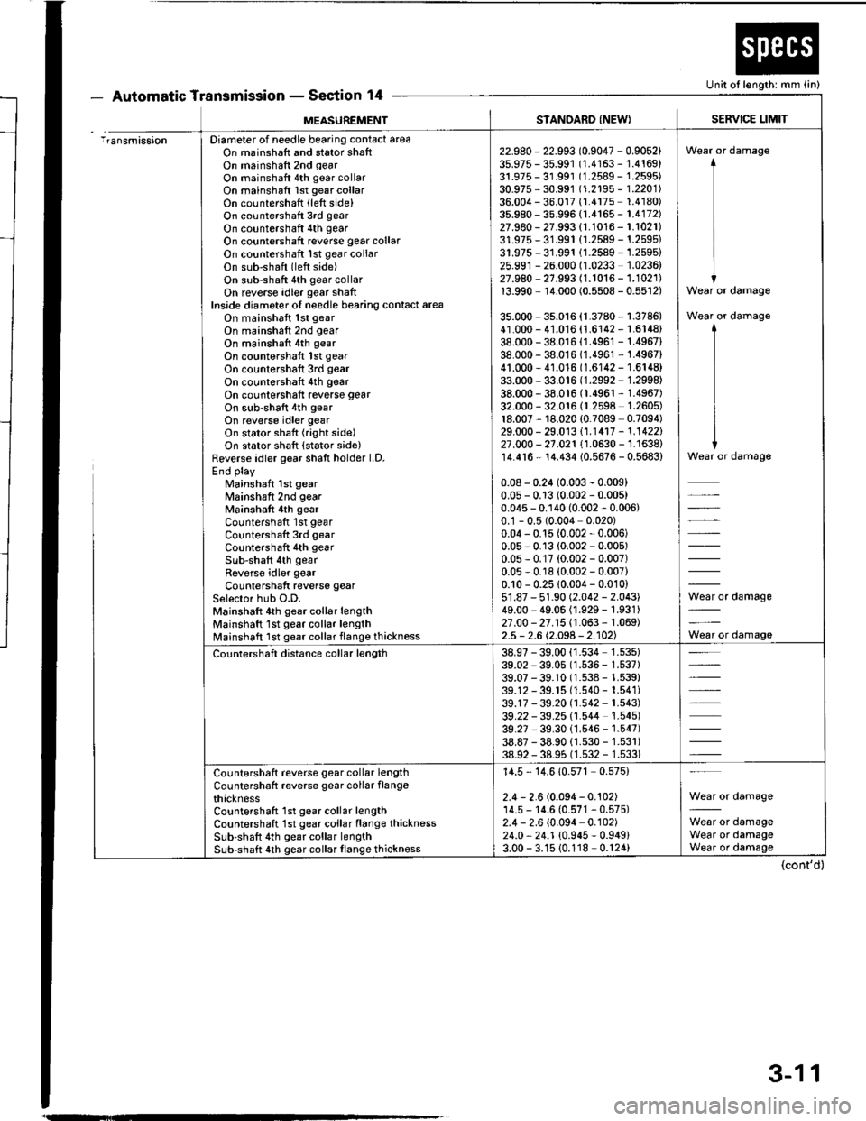
iransmissionDiameter of needle bearing contact areaOn mainshatt and stator shaftOn mainshaft 2nd gear
On mainshaft 4th gear collarOn mainshaft lst gesr collarOn countershaft (left side)On countershatt 3rd gear
On countershaft 4th gear
On countershaft reverse gear collarOn countershaft lst gear collaron sub'shaft (left side)On sub-shaft 4th gear collarOn reverse idler gear shaftInside diameter of needle bearing conlact areaOn mainshaft lst gear
On mainshaft 2nd gear
On mainshalt 4th gear
On countershaft lst gear
On countershaft 3rd gear
On countershaft 4th gear
On countershaft reverse gear
On sub-shatt 4th gear
On reverse idler gear
On stator shaft (right side)On stator shaft {stator side)Reverse idler gear shaft holder l.D.End play
Mainshaft 1st gearMainshaft 2nd gear
Mainshatt 4th gear
Countershaft 1st gear
Countershaft 3rd gear
Countershaft 4th gear
Sub-shaft 4th gearReverse idler gear
Countershaft reverse gear
Selector hub O.D.Mainshaft 4th gear collar lengthMainshatt'lst gear collar lengthlvlainshaft Ist g€ar collarflange thickness
22.980 - 22.993 (0.9047 - 0.9052)35.975 - 35.991 0.4163 - 1.4169)31.975 - 31.99r (1.2589 - 1.2595)30.975 - 30.991 t1.2195 - 1 .2201136.004 - 36.017 {r.4r7s - 1.4'�l80)35.980 - 35.996 (1.4165 - 1.4172)27.980 - 27.993 {1.1016 - 1.1021)31.975-31.991 (1.2589 - 1.2595)31.975 -31.991 (1.2589 - 1.2595)25.991 - 26.000 (1.0233 1.0236)27.980 - 27.993 (1.1016 - 1.1021)13.990 11.000 (0.5508 - 0.5512)
35.000 - 35.016 (1.3780 - 1.3786)41.000 - 41.016 {1.6142 - r.6148}38.000 - 38.016 (1.4961 - 1.4967138.000 - 38.0161'�].4961 - 1.4967)41.000 - 41.016 (1.6142 - 1.6148)33.000 - 33.016 (1.2992 - 1.2998)38.000 - 38.016 0.4961 - 1.4967)32.000 - 32.016 fl.2598 1.2605)18.007, 18.020 {0.7089 0.7094)29.000 - 29.013 (1.14r7 - 1.1422)27.000 - 21.021 (1.0630 - '�j.1638)
14.416 - 14.434 10.5676 - 0.5683)
0.08 - 0.24 (0.003 - 0.009)0.05 - 0.13 (0.002 - 0.005)0.045 - 0.140 (0.002 - 0.006)0.1 - 0.5 (0.004 0.020)0.04 - 0.15 (0.002 - 0.006)0.05 - 0.13 (0.002 - 0.005)0.05 - 0.17 (0.002 - 0.007)0.05 - 0. r8 (0.002 - 0.007)0.10 - 0.25 10.004 - 0.010)51.87 - 51.90 (2.042 - 2.043)49.00 - 49.05 (1.929 - 1.931)27.00 - 27.15 (1.063 - '�|.069)
2.5 - 2.6 \2.098 - 2.102)
Wear or damage
Wear or damage
Wear or damage
*rd"-"g"
Wear or damage
Countershaft distance collar length38.97 - 39.0039.02 - 39.0539.07 - 39.1039.12 - 39.r539.17 - 39.2039.22 - 39.2539.27 - 39.3038.87 - 38.9038.92 - 38.95
1.534 1.535)'r.536 - 1.537)1.538 - 1.539)1.540 - 1.541)r.542 - 1.543)1.544 1.545)1.546 - 1.547)1.530 - 1.53r)'1.532 - 1.533)
Countershaft reverse gear collar lengthCountershaft reverse gear collar flangethicknessCountershaft 1st gear collar lengthCountershaft '1st gear collar flange thicknessSub-shaft 4th gear collar lengthSub-shaft 4th gear collar flange thickness
14.5 - 14.610.57r 0.575)
2.4 - 2.6 (0.094 - 0.102)'14.5 - 14.6 (0.57'�l - 0.575)2.4 - 2.6 (0.094 0.102)24.0, 24.1 {0.945 - 0.949}3.00 - 3.15 {0.118 0.r24)
Wear or damage
Wear or damageWear or damageWear or damage
(cont'd)
3-11
Page 51 of 1413
Engine Removal/lnstallation
(cont'd)
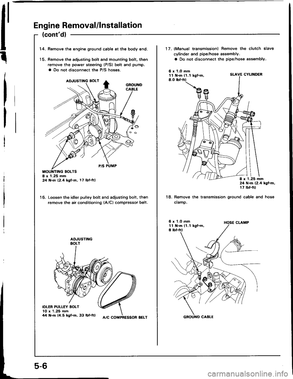
14.Remove the engine ground cable at the body end.
Remove the adiusting bolt and mounting bolt, then
remove the power steering (P/Sl belt and pump.
a Do not disconnect the P/S hoses.
8 r 1.25 mm24 N.m (2.4 kgf.m. 17 lbl.ftl
6. Loosen the idler pulley bolt and adjusting bolt, then
remove the air conditioning (A/C) compresso. belt.
IDLER PULLEY BOLT10 x 1.25 mm44 N.m 14.5 kgt.m, 33 lbl.ftl
5-6
A/C COMPRESSOR BELT
17. (Manusl transmission) Remove the clutch slave
cylinder and pipe/hose assembly.
a Do not disconnect the pipe/hose assembly.
6 x 1.O rl|mll N.m { 1.1 kgt.m,SLAVE CYLINDER
8.0
8 x 1.25 mm24 N.m {2.4 kgl.m,17 lbt.ftl
18. Remove the transmission ground cable and hose
cramp.
6 x 1.O mm1l N.m 11 ,1 kgt.m,I tbt.ftl
Page 73 of 1413
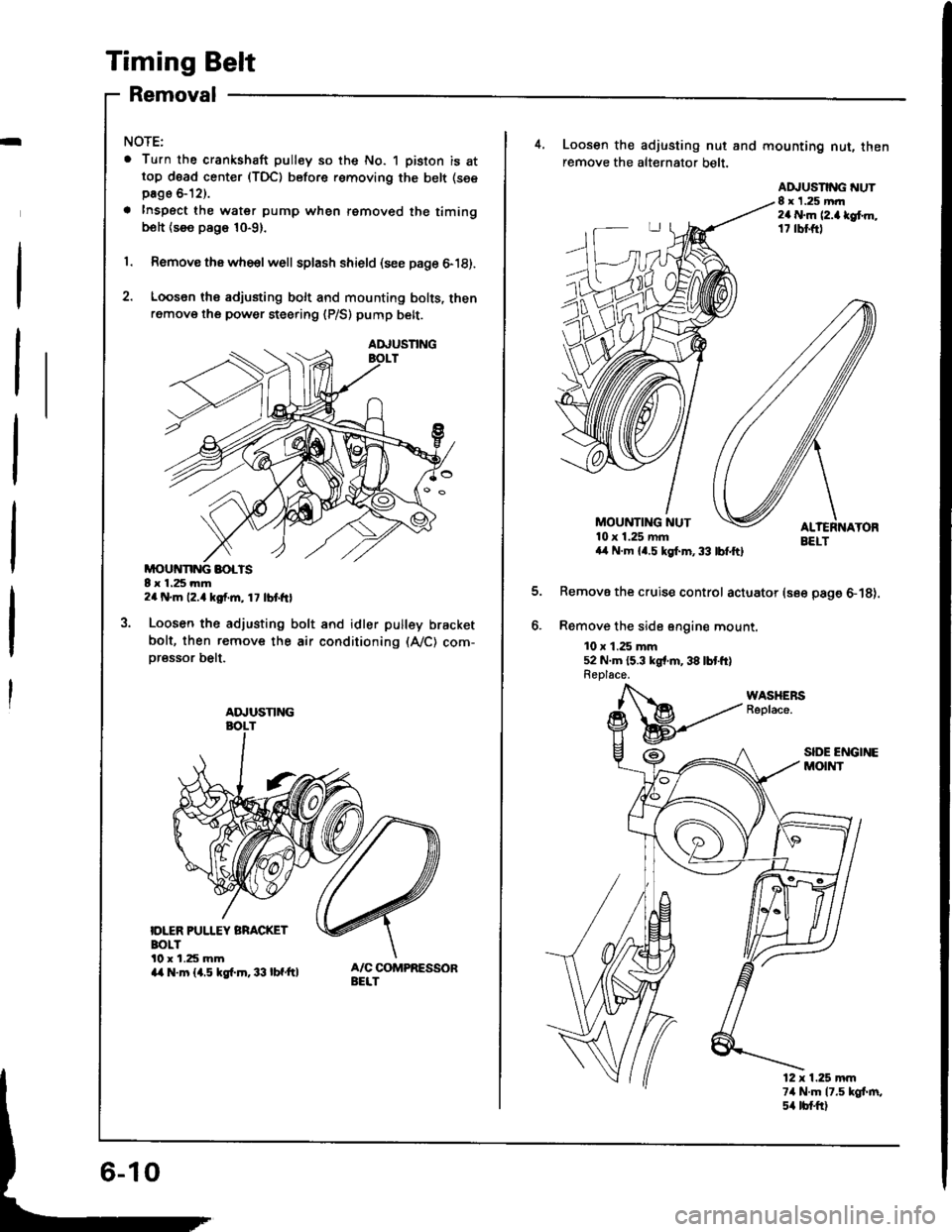
Timing Belt
Removal
I
NOTE:
. Turn the crankshaft pulley so the No. 1 piston is attop d6ad center (TDC) before removing the belt (see
page &12).
a Inspect the water pump when removed the timingbolt {see page 10-9}.
1. Remove thawhe€lwell splash shield (see page 6-18).
2. Loosen ths adjusting bolt and mounting bolts, thenremove the power steering {P/S) pump belt.
MOUivNNG BOLTS8 x 1.25 mm2a N.m 12.4 kgf.m, 1 7 lbt frl
Loosen the adjusting bolt and idler pulley bracket
bolt, then remove the air conditioning (A,/C) com-
oressor belt.
IDLER PUI.IEY BRACKETBOLTl0 r 1.25 mma/a N.m {1.5 kgf.m.33 lbf'ft}
AA,USNNG
ADJUSTING
4, Loosen the adjusting nut and mounting nut, thenremove the alt€rnator belt.
EELTa,l N.m {4.5 kgl.m,33 lbfftl
Remove the cruise control actuator (see page 6-18).
Remove the sid6 sngine mount.
10 x 1.25 mm52 N.m {5.3 kgr'm,38 lbtft}Replace.
MOUNTING NUT10 x 1.25 mm
ADJUSNNG NUT8 x 1.25 mrr2a N.m l2.a lef.m,17 rbl.ftl
12 x 1.25 mm74 N.m 17.5 kgt m,s4 tb{.ftl
Page 110 of 1413
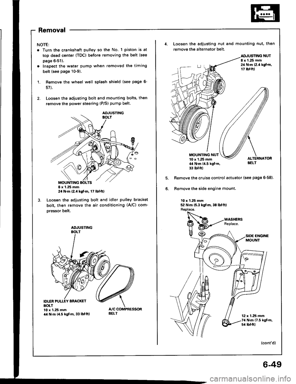
Removal
NOTE:
. Turn the crankshaft pulley so the No. 1 piston is at
top dead center {TDC) before removing the belt (see
page 6-51).
. Inspect the water pump when removed the timing
belt {see page 10-9).
Remove the wheel well splash shield (see page 6-
57 ).
Loosen the adiusting bolt and mounting bolts, then
remove the power steering (P/S) pump belt.
I x 1.25 mm2a N.m l2.a kgt.m, 17 lbt ttl
Loosen the adjusting bolt and idler pulley bracket
bolt, then remove the air conditioning (Ay'C) com-
oresso. belt.
D1INBOLT10 x 1.25 mmira N.m (4.5 kgf.m, 33 lbf'ttl
AOJUSTING
ADJUSNNG
BELT
4. Loosen the adiusting nut and mounting nut, then
remove the alternator belt.
NUTI x 1.25 mm24 N.m {2.a lgf.rn,17 tbf.ftl
MOUNTING NUT10 x 1.25 mm4,t N.m lia.5 kgl.m,33 tbt ftl
Remove the cruise control actuator (see page G58).
Bemove the side engine mount.
10 x 1.25 mm52 N.m 15.3 kgt m, 38 lbtftl
CNGINCMOUNT
12 x 1.25 mm74 N.m (7.5 kgt m,s4 lbf.trl
(cont'd)
6-49
Page 180 of 1413
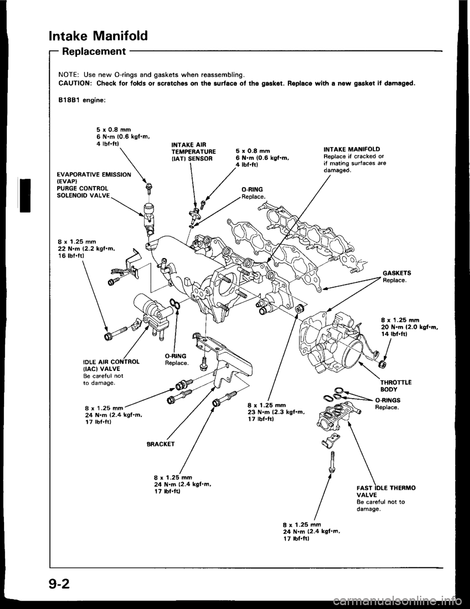
Intake Manifold
Replacement
NOTE: Use new O-rings and gaskets when reassembling.
CAUTION: Check for tolds or scratches on the aurface ot the gasket. Roplace with a now gasket it damagod,
81881 engine:
5r0.8mm6 N'm {0.6 kgl.m.4 rbr.ftlINTAKE AIRTEMPERATUREIIATI SENSOR
'*o*ot'u""'""N
5xO.8mm6 .m (0.6 kg{.m.4 tbf.ftl
O-RINGReplace.
IiITAKE MANIFOLDReplace iI cracked orit mating s!rtaces arodamag€o.
PURGE CONTROLSOLENOID VALVE
8 x 1.25 mm22 N.r 12.2 kgl.m,'16 tbt.ftt
IDLE AIR
GASKETSReplace.
I x 1.25 mm20 N.m (2.0 kgt.m.14 rbf.ftl
O.RINGReplace.{IACI VALVEBe careful notto damage.THROTTLE
8 x 1.25 mm
BODY
O-RINGSBeplace.
24 N.m (2.4 kgf'm,17 rbf.ft)
8 x 1.25 mm23 N.m (2.3 kgl.m,17 lbf.frl
BRACKET"o
aYc
g
/
1.25 mmN.m (2.4 kgl'm,rbf'ft1
8x2417
8 x 1.25 mm24 N.m (2.4 kgl'm.17 tbr.ftlTHERMOVALVE8e careful not todamage.
9-2
Page 187 of 1413

ENGINE COMPARTMENT HOSE CONNECTIONS:
Bl88l engine:FAST IDLETHERMOVALVE
THERMOSTATHOUSIITGIDLE AIR CONTROLIIAC} VALVE
O'RINGReplace.
BREATHER PIPE
O-RINGReplace.
HEATER HOSES
818C1 engine:
ENGINE OILCOOLER
IAC VALVE
HEATER BYPASSPIPE
FAST IDLETHERMOVALVE
THERMOSTATHOUSING
BREATHER PIPE
HEATEB HOSES
10-3
Page 196 of 1413
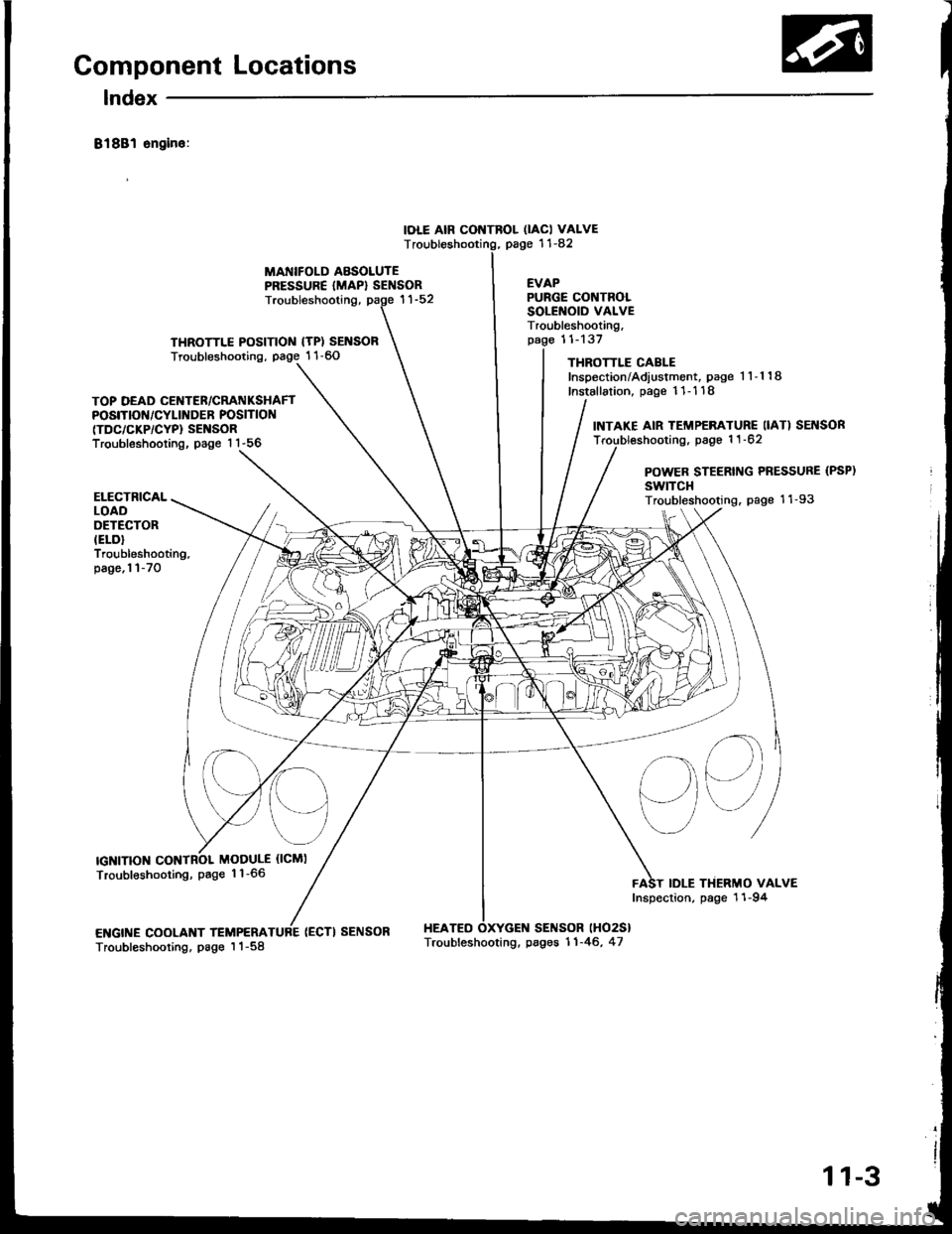
Component Locations
lndex
81881 sngin6:
IOLE AIR CONTROL OACI VALVEpage '11-82T
MANIFOLD ABSOLUTEPRESSURE {MAP} SENSOREVAP
THROTTLE POSITIOIII {TP) SENSORTroubleshooting, page 1 1-60
Troubleshooting,
(ECTI SENSOR HEATEO
PURGE CONTROLSOLENOID VALVETroubleshooting,11-137
THROTTLE CABLEInspection/Adiustment, page 1 1-1 18
Installation, page 11- 1 18
SENSOR lHO2S}
TOP DEAD CENTER/CRATIIKSHAFTPOSITIOf{/CYLINDER POSITION(TDC/CKP/CYP} SENSORTroubleshooting, page 1 1-56
INTAKE AIR TEMP€RATURE IIAT) SEI{SORTroubl€shooting, page 1 1 -62
POWER STEERING PRESSURE (PSP)
swtTcHTroubleshooting. page 11-93
sq
IDLE THERMO VALVEInspection, page 11-94
ELECTRICALLOADOETECTORIELD}Troubleshooting.page,l l-70
IGNITIONMODULE {ICMI
Troubleshooting, page 1 1-66
ENGINE COOLANT TEMPERATroubleshooting, page I 1-58Troubleshooting. pages 11-46, 47
11-3
Page 197 of 1413
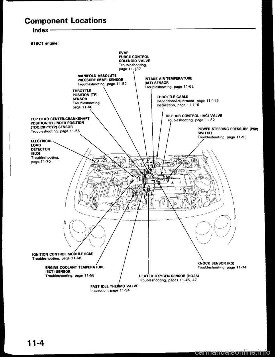
Component Locations
lndex
B18Cl ongino:
THROTTLEPOSITION (TP}
SENSOR
MANIFOLD AESOLUTEPRESSURE (MAPI SENSOR
Troubleshooting, page 1 1-52
EVAPPURGE CONTROLSOLEiIOID VALVETroubleshooting,page 11-137
VALVE
INTAKE AIR TEMPERATURE
IIAT) SENSORpage 11-62
THROTTLE CABLEInspection/Adiustment, page 'l 1-1 19
lnstallation, page 1 1-1 19
IOLE AIF CONTROL (IACI VALVETroubleshooting. page 1 1 -82
Troubleshooting,page 1 1-6O
TOP DEAD CENTER/CRANKSHAFTPOSITION/CYLINDER POSITION
{TDC/CKP/CYPI SEI{SORTroubl€shooting. Page 1 1 -56POWER STEERING PRESSURE (PS'I
swtTcHTroubleshooting, page 1 1-93ELECTRICALLOADDETECTORIELD}Troubleshooting,page.1 1-70
IGNITION CONTNOL MODULE OCMI
Troubleshooting, Psge 1'l-66
ENGIT{E COOLANT TEMPERA
{ECT} SEI{SORTroubleshooting, Pag€ 1 1-58
sElrlsoR tKslTroubfeshooting, page 1 1 -7 4
HEATED OXYGEN SENSOR (HO2S}
Troubleshooting, pages 11-46, 47
FAST IDLEInspection, page 1 'l -94
11-4