Ignition coil HONDA INTEGRA 1994 4.G Workshop Manual
[x] Cancel search | Manufacturer: HONDA, Model Year: 1994, Model line: INTEGRA, Model: HONDA INTEGRA 1994 4.GPages: 1413, PDF Size: 37.94 MB
Page 443 of 1413
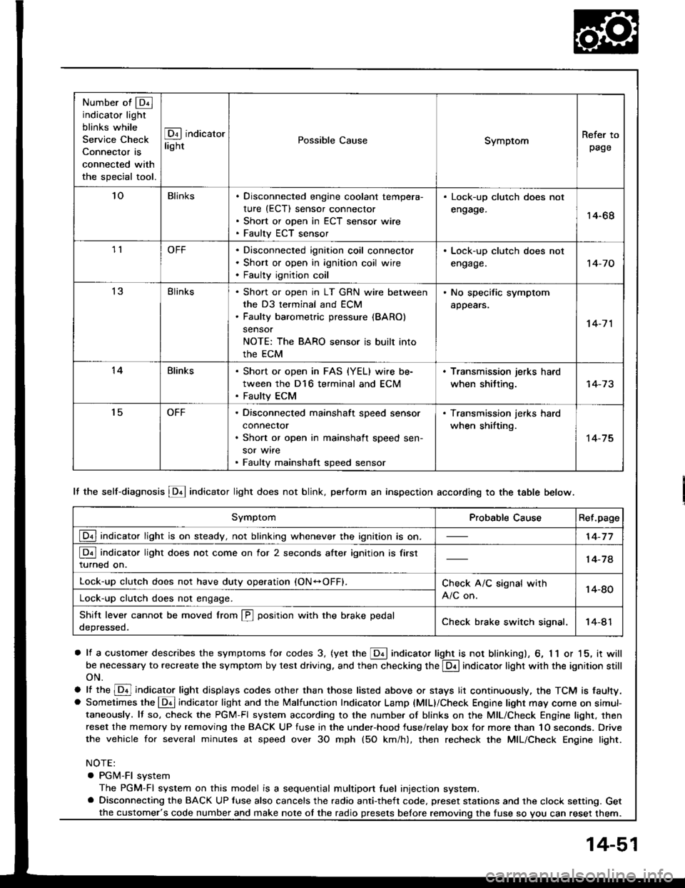
Number of @indicator light
blinks while
Service Check
Connector is
connected with
the special tool.
@ indicator
lightPossible CauseSymptomRefer to
page
'loBlinksDisconnected engine coolant tempera-
rure (ECT) sensor connector
Short or open in ECT sensor wire
Faulty ECT sensor
Lock-up clutch does not
engage.14-68
1lOFFDisconnected ignition coil connector
Short or open in ignition coil wire
Faulty ignition coil
. Lock-up clutch does not
engage.'t 4-7 0
13Blinks. Shon or open in LT GRN wire between
the D3 terminal and ECM. Faulty barometric pressure {BARO)
sensor
NOTE: The BARO sensor is built into
the ECM
. No specific symptom
appears.
14-7 1
14Blinks. Short of open in FAS {YEL} wire be-
tween the D16 terminal and ECM. Faulty ECM
. Transmission jerks hard
when shitting.
't5OFFDisconnected mainshaft speed sensor
connecror
Short or open in mainshaft speed sen-
sor wire
Faulty mainshaft speed sensor
. Transmission jerks hard
when shifting.
14-75
SymptomProbable CauseRet.page
LQ! indicator light is on steady, not blinking whenever the ignition is on.14-77
[Q3] indicator light does not come on for 2 seconds after ignition is first
turned on.14-78
Lock-up clutch does not have duty operation (ON-OFFI.Check A/C signal with
A/C on.14-80Lock-up clutch does not engage.
Shitt leve. cannot be moved lrom @ position with the brake pedal
depressed.Check brake switch signal,14-41
It the self-diagnosis LQ4 indicator light does not blink, perform an inspection according to the table below.
a lf a customer describes the symptoms for codes 3, (yet the LQ! indicator light is not blinkingl, 6, 1 1 or 15, it will
be necessa.y to recreate the symptom by test driving. and then checking the @ indicator light with the ignition still
oN.
e lt ttre @ indicator light displays codes olher than those listed above or stays lit continuously, the TCM is faulty.. Sometimes the Lqd indicator light and the Malfunction Indicator Lamp (MlL)/Check Engine light may come on simul-taneously. lf so, check the PGM-Fl system according to the numbe. of blinks on the MIL/Check Engine light. thenreset the memory by removing the BACK UP fuse in the unde.-hood fuse/relay box for more than 1O seconds. Drive
the vehicle for several minutes at speed over 30 mph (5O km/h), then recheck the MIL/Check Engine light.
NOTE:
. PGM-FI system
The PGM-Fl system on this model is a sequential multiport fuel injection system.a Disconnecting the BACK UP luse also cancels the radio anti-theft code. preset stations and the clock setting. Get
the fuse so vou can reset them.the customer's code number and make note ot the radio
14-51
Page 462 of 1413
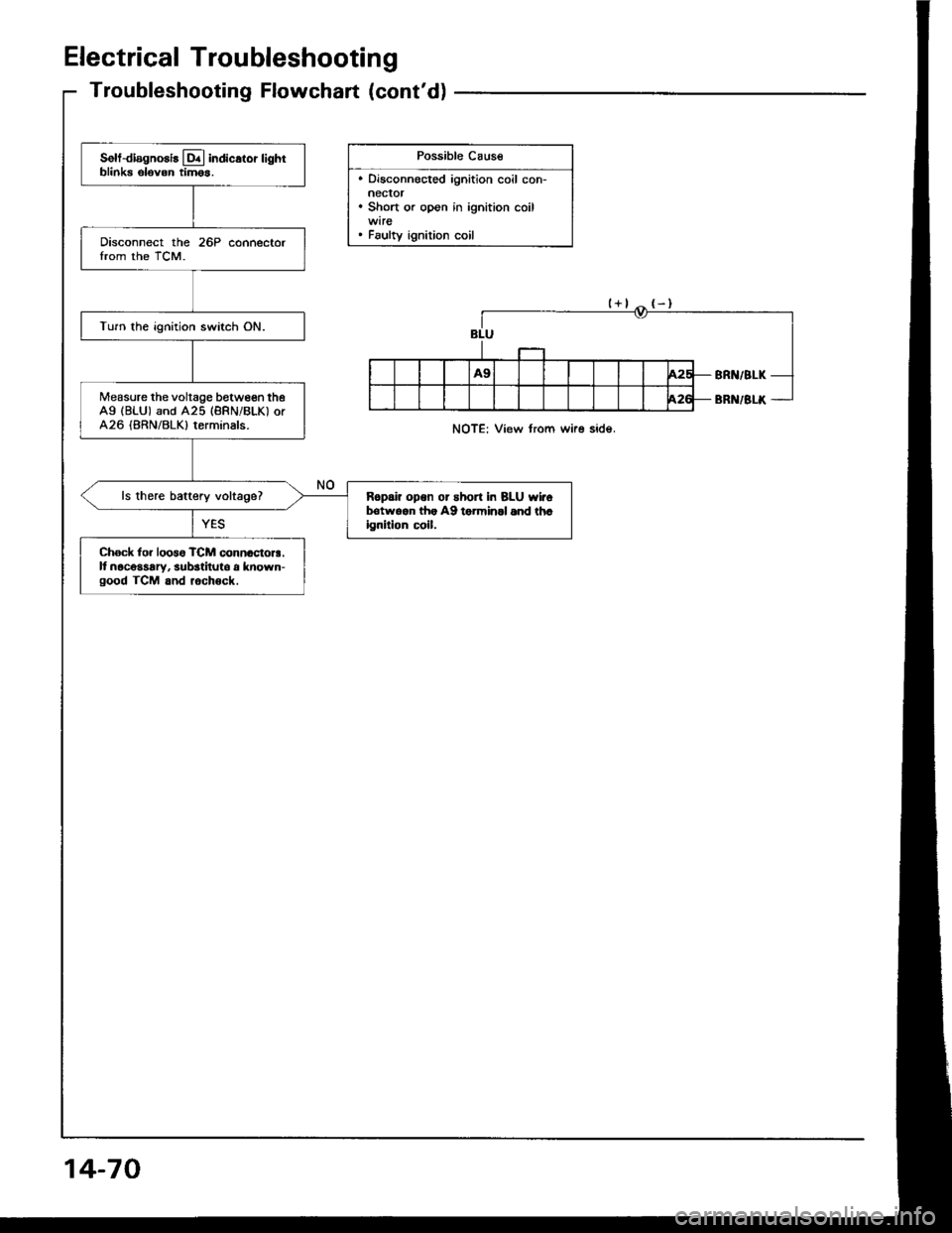
Electrical Troubleshooting
Troubleshooting Flowchart (cont'd)
Possible Cause
. Disconnected ignition coil con-neclor. Short or open in ignition coil
. Faulty ignition coil
Solt-diagnosis lq.l indicstor lightblinks elovon tim6s.
Disconnect the 26P connectorIrom the TCM.
Turn the ignition switch ON.
Measure the voltage between theAg (BLU) and A25 (BRNiBLK) orA26 (BRN/BLK) terminals.
ls there baftery voltage?R6pai? opon or short in BLU wirolrotwqan lh. A9 torminll 6nd th.ignilion c!il.
Ch6ck lor loos6 TCM connactora.It nacosaary, substituto a known-good TCM and rochock.
NOTE: View from wire side.
14-70
Page 1182 of 1413
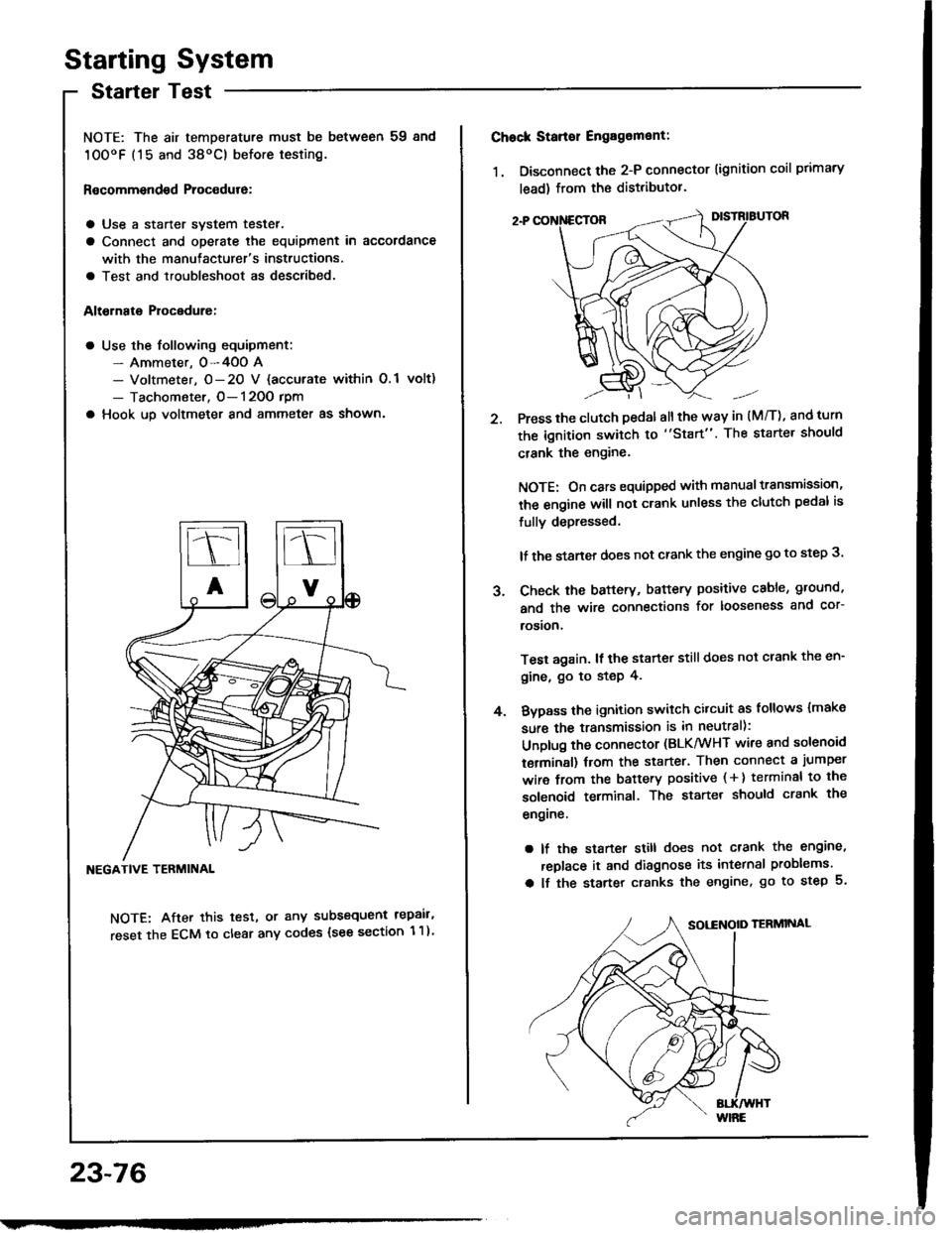
Starting System
Startel Test
NOTE: The air temDerature must be between 59 8nd
10OoF (15 and 38oC) before testing.
Recommendsd Procodure:
a Use a staner svstem tester.
a Connect and operate the equipment in accordance
with the manutacturer's instructions.
a Test and troubleshoot as described.
Altohato Procedure:
a Use the following equipment:- Ammeter. 0-4OO A- Voltmeter, O- 20 V {accurate within 0.1 volt)
- Tachometer, O- 120O rpm
a Hook up voltmeter and ammeter as shown'
NEGATIVE TERMINAL
NOTE: After this test, or any subsequent repair,
reset the ECM to clear any codes (see section 1 1)
23-76
2.
Chock Stan€r Engag6ment:
1. Disconnect the 2-P connector (ignition coil primary
lead) from the distributor.
Press the clutch pedal allthe way in (M/T), and turn
the ignition switch to "Start". The starter should
crank the engine.
NOTE: On cars equipped with manual transmission,
the engine will not crank unless the clutch pedal is
fully depressed.
lf the staner does not crank the engine go to step 3.
Check the baftery, battery positive cable, ground,
and the wire connections for looseness and cor-
rosion,
Test again. lf the starter still does not crank the en-
gine, go to step 4.
Bvpass the ignition switch citcuit as follows {make
sure the transmission is in neutral):
Unplug the connector (BLK/WHT wire and solenoid
terminsl) trom the starter. Then connect a jumper
wire from the battery positive ( + ) terminal to the
solenoid terminal. The starter should crank the
engrne.
a lf the starter still does not crank the engine,
replace it and diagnose its internal problems.
a lf the starter cranks the engine, go to step 5.
J.
4.
Page 1193 of 1413
lgnition System
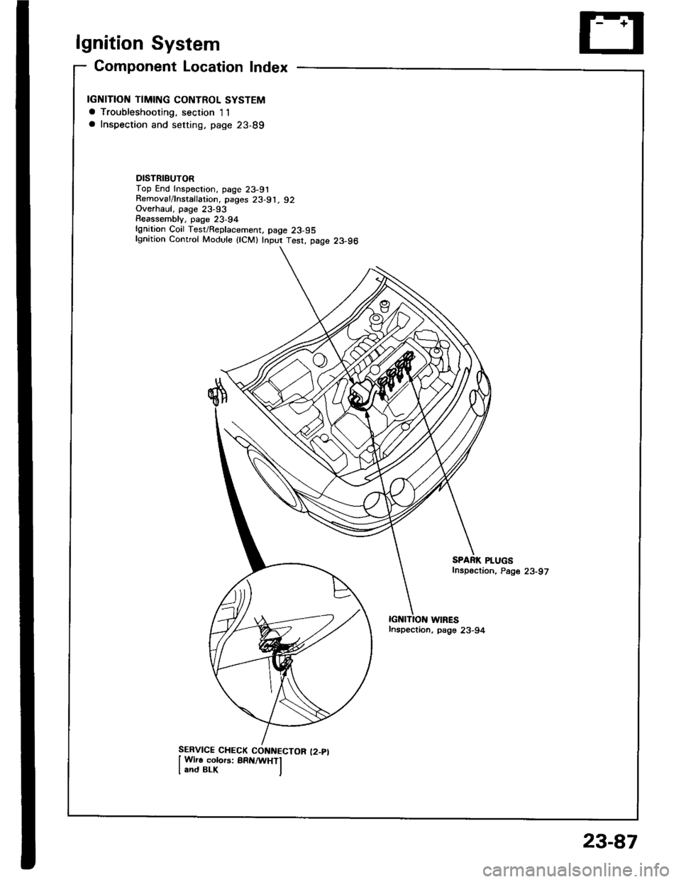
Gomponent Location Index
IGNITION TIMING CONTROL SYSTEMa Troubleshooting, section I1a Inspection and setting, page 23-89
DISTRIBUTORTop End Inspection, page 23-91Removal/lnstallation, pages 23-91, 92Overhaul, page 23-93Reassemblv, page 23,94lgnition Coil Test/Replacement, page 23-95lgnition Control Module {lCM} Inpur Test, page 23-96
WIRESInspection, psge 23-94
SPARK PLUGSfnspection, Page 23-97
23-87
Page 1201 of 1413
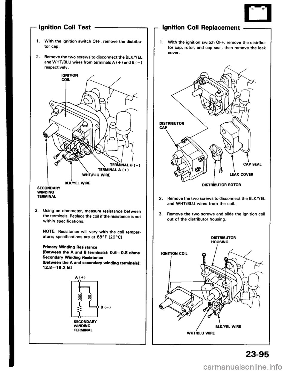
lgnition Coil Test
With the ignition switch OFF, remove the distribu-
lor cap.
Remove the two screws to disconnect the BLK^/EL
and WHT/BLU wires from terminals A (+ ) and B ( - )respectively.
3. Using an ohmmetet, measur€ tesistance betwe€nthe terminals, Replace the coil if the resistance is notwithin specifications.
NOTE: Resistance will vary with th€ coil t€m9er-ature; sp€cifications are at 68oF l20oC)
Prlmary Winding Rosistanco(8otwo6n tho A and B torminalsl: 0.6-0.g ohmsSecondary Winding Rssistanc6(Botwoon the A and socondary winding tomlnalsl:12.8 - 19.2 kO
lgnition Coil Replacement
1 . With the ignition switch OFF, remove the disrribu-
tor cap, rotor, and cap seal, then remove the leak
cover.
Remove the two screws to disconnect the BLK/YEL
and WHT/BLU wires from the coil.
Remove the two screws and slide the ignition coil
out of the distributor housing,
CAP SEAL
3.
A l+)
I
t
l
11
L
WHT/BLU WIRE
B {-}
23-95
Page 1202 of 1413
lgnition
lgnition
System
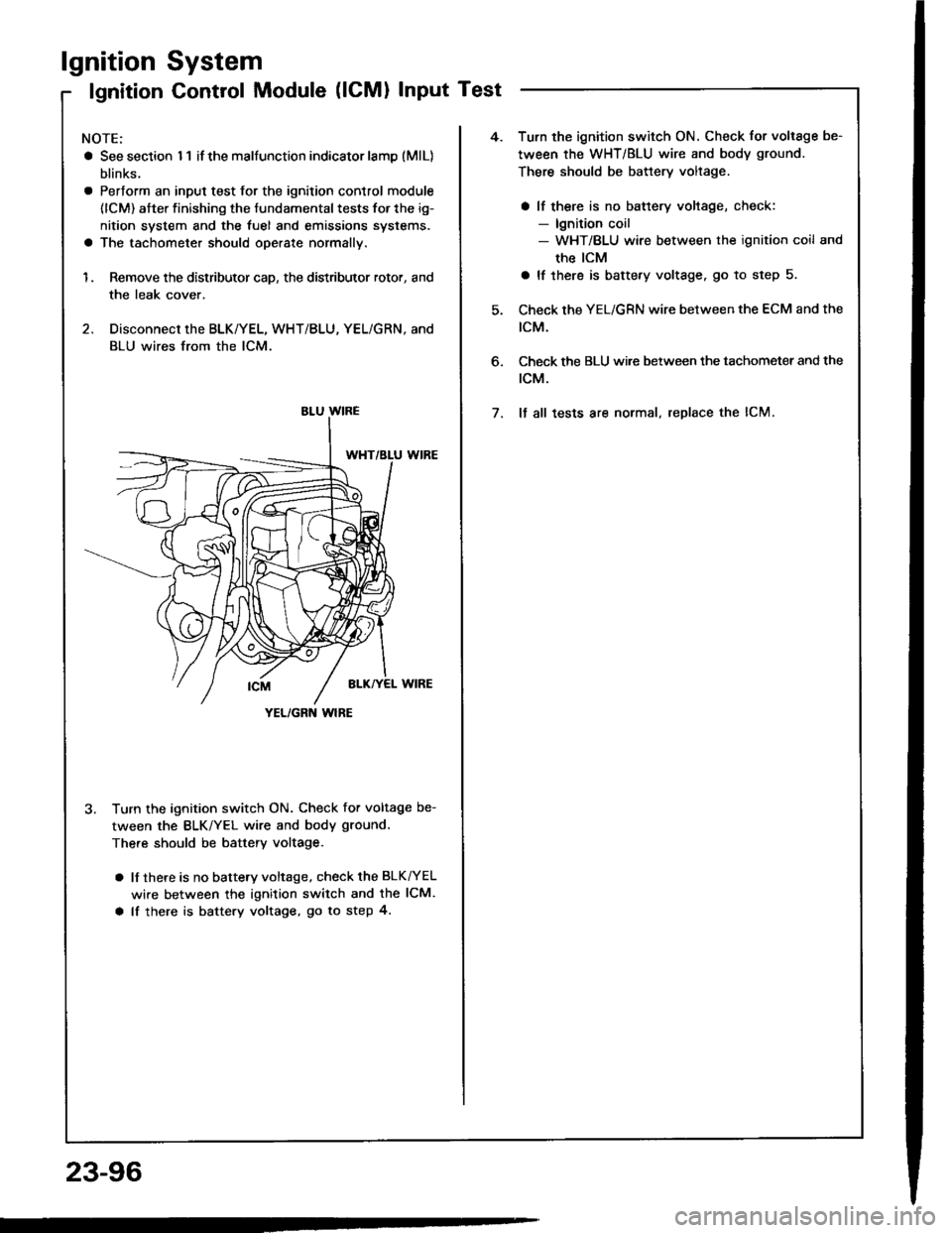
Control Module (lCMl Input Test
NOTE:
a See section I 1 if the malfunction indicator lamD (MlL)
blinks.
a Pertorm an input test for the ignition control module
(lCM) after finishing the fundamental tests for the ig-
nition system and the fuel and emissions systems.
a The tachometer should operate normally.
1. Remove the distributor cap, the distributor rotor, and
the leak cover.
2. Disconnect the BLK/YEL, WHT/BLU, YEL/GRN, and
BLU wires from the lCM.
3. Turn the ignition switch ON. Check for voltage be-
tween the BLK/YEL wire and body ground.
There should be battery voltage.
a lf there is no battery voltage, check the BLK^/EL
wire between the ignition switch and the lCM.
a lf there is battery voltage, go to step 4.
YEL/GRN wlRE
4.Turn the ignition switch ON. Check for voltage be-
tween the WHT/BLU wire and body ground.
There should be battery voltage.
a lf there is no battery voltage, check:- lgnition coil- WHT/BLU wire between the ignition coil and
the ICM
a lf there is battery voltage. go to step 5.
Check the YEL/GRN wire between the ECM and the
tcM.
Check the BLU wi.e between the tachometer and the
rcM.
It all tests are normal, replace the lCM.
6.
7.
23-96
Page 1203 of 1413
Spark Plug Inspection
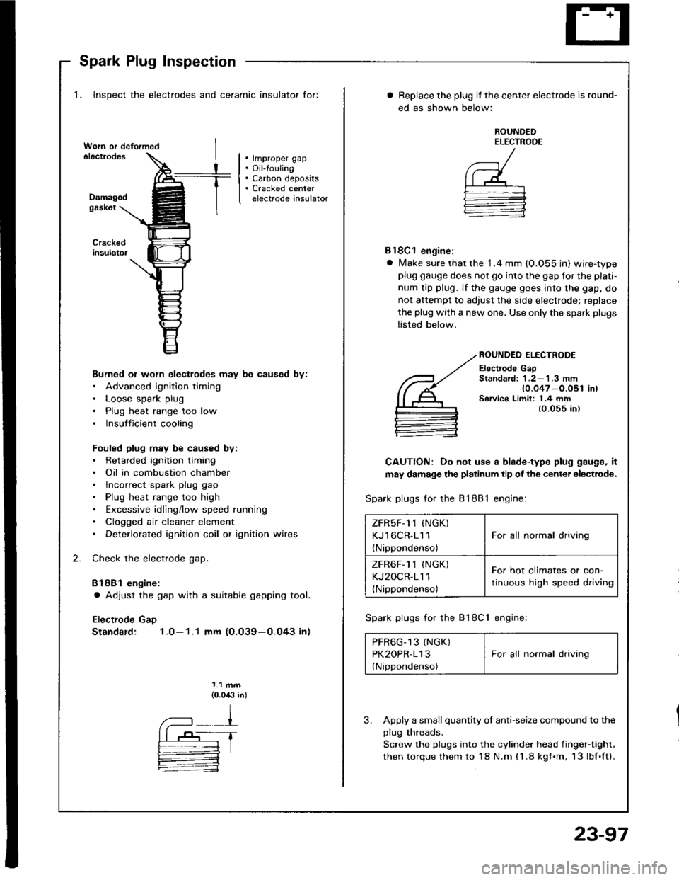
1. Inspect the electrodes and ceramic insulator for:
. rmproper gap. Oil-touling. Carbon deposits. Cracked centerelectrode insulatorDamagedgask6t
Burned or worn electlodes may be caused by:. Advanced ignition timing. Loose spark plug. Plug heat range too low. Insufficient cooling
Fouled plug may be caused by:. Retarded ignition timing. Oil in combustion chamber. lncorrect spark plug gap. Plug heat range too high. txcessive idling/low speed running. Clogged air cleaner element. Deteriorated ignition coil or ignition wires
Check the electrode gap.
Bl88l engine:
a Adjust the gap with a suitable gapping tool.
Electrode Gap
Standard: 1.0-1.1 mm (O.O39-0.O43 in)
1.1 mm{0.0,$ in)
Replace the plug if the center electrode is round-
ed as shown below:
ROUNDEDELECTROOE
Bl8Cl engine:
a Make sure that the '1.4 mm (0.055 in) wire-typeplug gauge does not go into the gap for the plati-
num tip plug. lf the gauge goes into the gap, do
not attempt to adjust the side electrode; replace
the plug with a new one. Use only the spark plugs
listed below.
ROUNDEO ELECTRODE
Electrode GapStandard: 1 .2-'l .3 mm{0.047 -O.051 in)Service Limit: 1.4 mm{0.055 in)
CAUTION: Do not use a blade-type plug gaugs, it
may damage the platinum tip of the center olectrodo.
Spark plugs for the 81881 engine:
Spark plugs for the B'l8Cl engine:
PFR6G_13 (NGK) IPK2OPR-113 I For all normal driving
{Nippondenso)
3. Apply a small quantity ol anti-seize compound to the
plug threads.
Screw the plugs into the cylinder head iingef-tight,
then torque them to 18 N.m (1.8 kgf.m, 13lbf.ft).
ZFRsF-1 1 (NGK)
KJl6CR-11 1
(Nippondenso)
For all normal driving
ZFR6F-1 1 (NGK)
KJ2OCR-11 1(Nippondenso)
For hot climates or con-
tinuous high speed driving
23-97