Wheel HONDA INTEGRA 1994 4.G Workshop Manual
[x] Cancel search | Manufacturer: HONDA, Model Year: 1994, Model line: INTEGRA, Model: HONDA INTEGRA 1994 4.GPages: 1413, PDF Size: 37.94 MB
Page 4 of 1413
,,
SUPPLEMENTAL RESTRAINT SYSTEM (SRS}
The Integra SRS includes a driver's airbag, located in the steering wheel hub. ln addition, all mod€ls excepi tna
Rs model for canada have a front passenger's airbsg located in the dashboard above the glove box, InformaUon
necessary to safely service the SRS is included in this servica Manual. ltems marked with an sstorisk (r) on thr
contents page include, or are located near, SRS components. Servicing. disassembling or roplacing thea6 ltems
will require special precautions and tools, and should thoreiore be done by an authorhed Acura dealer.
' To avoid rondering ths sRS inoporativo, which could lard to porronll Injury or darth In thc cvant ot. r.yr.
trontal collision, all sRs sorvico work must be pcrformcd by !n ruthorizcd Acu.! daerrr,
' lmpTopor 3orvica proceduroa, including inco.roct r.movd r d Installation of tha SRS, could Lld to pc[onc Inlu-
ry caussd by unintsntional activation ot tho airbags.
' All sRs oloctrical wiring harnoa$! aro coverod with yallow In3ulatlon, Rcbtcd componcnts arc bcrtad In tha
stoering Golumn, front console, dsrhboa.d, and darhboard lowor plnol, lnd in thc d$hbolrd abovc tha gaov!
bor. Do not uas oloctdcal te$ oquipmont on thaaa citcuhs.
NoTE: The original radio has a coded thett protection circuit. Be sure to get the customer's code numb6r b€lore* disconnecting the battery.
- removing the No. 32 (7.S A) fuse Jrom the undsr-hood fuse/relay box.
- removing the radio.
After service, reconnect power to the radio and turn it on. When the word ,,CODE,, is displayed, enter the cus_
tomer's 5-digit code to restore radio oDerauon.
Page 9 of 1413
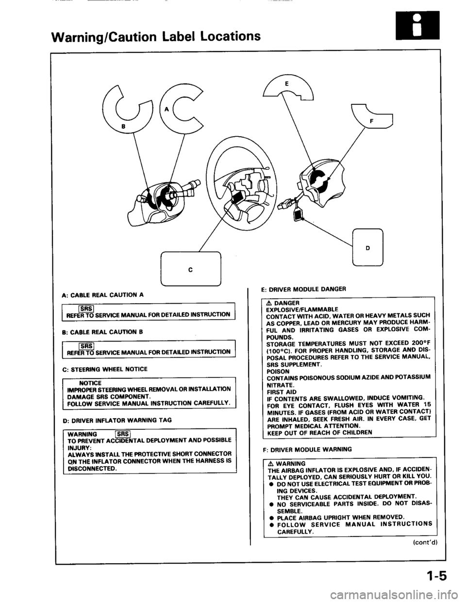
Warning/Caution Label Locations
BEFERTO- SERVICE MANUAL FOR DETAII'fD INSTRUCTION
E: DRIVER MODULE DANG€R
A: CABLE REAL CAUTION A
B: CABLE BEAL CAUTION B
A DANGER
EXPLOSIVE/FLAMMABLE
CONTACT WITH ACID, WATER OR HEAVY METALS SUCH
AS COPPER, LEAD OR MERCURY MAY PRODUCE HARM.
FUL AND IRFITATING GASES OR EXPLOSIVE COM.
POUNDS.
STORAGE T€MPERATURES MUST NOT EXCEED 2OOOF
(1OOOCI. FOR PROPER HANDLING. STORAGE AND DIS-
POSAL PROCEDURES REFER TO THE SERVICE MANUAL,
SRS SUPPLEMEf{T.
POTSON
CONTAINS POISONOUS SODIUM AZIDE AND POTASSIUM
I{ITRATE.
FIRST AID
IF CONTENTS ARE SWALLOWED, INDUCE VOMITING.
FOR EYE CONTACT, FLUSH EYES WITH U'ATER 15
MINUTES. IF GASES IFROM ACID OR WATER CONTACT}
ARE INHALED. SEEK FRESH AIR. IN EVERY CASE, GET
PROMPT MEDICAL ATTENTION.
KEEP OUT OF REACH OF CHILDREN
REFERTO- SERVICE MAI{UAL FOR OETAILED INSTRUCTION
C: STEERII{G WHEEL OTICE
]{OT|CE
IMPROPEB STEERII{G WIIEEL REMOVAL OR INSTALLATION
DAMAGE SRS COMPONENT.
FOLLOW SERVICE MANUAL INSTRUCTION CAREFULLY.
D: DRIVER INFLATOR WAR[{|NG TAG
WARNII{G
TO PflEVE T ACCIDE]TTAL D€PLOYMENT AND POSSIBLE
INJURY:
ALWAYS II{STALL THE PNOTECTIVE SHORT COI{NECTOR
O THE INFLATOR COI{I{ECTOR WHEN THE HARNESS IS
DISCONNECTED.
F: DRIVER MODULE WARNING
A, WABNING
THE AIRBAG INFLATOR IS EXPLOSIVE AND' IF ACCIDEN-
TALLY DEPIOYED, CAN SERIOUSLY I{URT OR KILL YOU.
. DO NOT USE ELECTRICAL TEST EOUIPMEI'IT OR PROB-
ING DEVICES.
THEY CAN CAUSE ACCIOENTAL OEPLOYMENT.
. NO SERVICEABLE PARTS INSIOE, DO NOT DISAS.
SEMALE.
. PLACE AIRBAG UPRIGXT WHEN REMOVED'
. FOLLOW SERVICE MANUAL II{STRUCTIONS
CAREFULLY.
(cont'd)
1-5
Page 13 of 1413
![HONDA INTEGRA 1994 4.G Workshop Manual Lift and Support Points
Lift
Wh€n heavy 16ar compon€nts such aa susponsion, luel tank, spale tile and hatch ale to
il]iii6iliieigltt in the tuggage area bsfore hoisting. When substantial woight is HONDA INTEGRA 1994 4.G Workshop Manual Lift and Support Points
Lift
Wh€n heavy 16ar compon€nts such aa susponsion, luel tank, spale tile and hatch ale to
il]iii6iliieigltt in the tuggage area bsfore hoisting. When substantial woight is](/img/13/6067/w960_6067-12.png)
Lift and Support Points
Lift
Wh€n heavy 16ar compon€nts such aa susponsion, luel tank, spale tile and hatch ale to
il]iii6iliieigltt in the tuggage area bsfore hoisting. When substantial woight is lemoved from ths
b€ removod, plac6
l€ar ol th€ car, ths
cantor of gravity may chango and can cause the cal to tip folward on the hoist'
NOTE: Since each tire/wheel assembly weighs approximately 14 kg (30 lbs), placing the front wheels in trunk can assist
with the weight distribution.
1. Place the lift blocks as shown
2. Raise the hoist a lew inches (centimeters) and rock the car to be sure it is firmly supported.
3. Raise the hoist to full height and inspect lift points for solid support.
FRONT SUPPORT POINTLIFT BLOCKSBEAR SUPPORT POINT
1-9
Page 14 of 1413
and Support Points
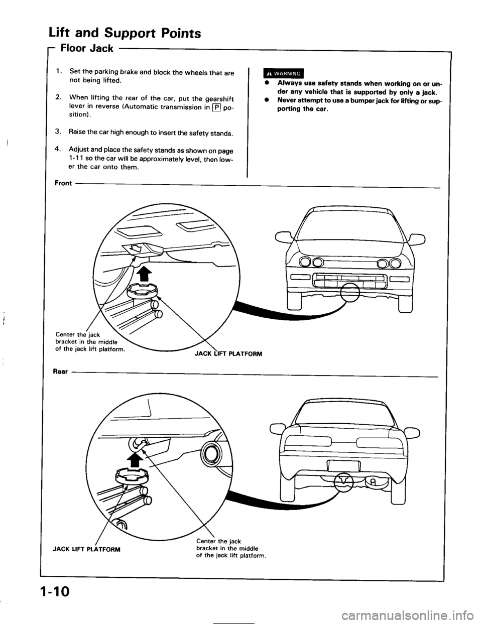
Jack
Set the parking brake and block the wheels that are
not being lifted.
2.When lifting the rearwhen tritrng the rear of the car, put the gearshift
lever in reverse (Automatic transmission in @ po-
of
sition).
Raise the car high enough to insen the safety stands.
Adjust and place the safety stands as shown on page
1-1 1 so the car will be approximately level, then low-
er the car onto them.
Front
oor
ft
FI
Li
4.
1.
a
Always uss satety stands when working oo 01 un-
der any vehicle that is supponed by only a jack.
Naver attompt to use a bumpor iack fo. lifting or sup-
porting tho car,
3.
Center the
bracket in
ot the jack
the middle
lift platform.
jsck
JACK LIFT PLATFORM
Rear
JACK LIFT PLATFORM
Center the jack
bracket in the middle
of the jack Iift platform.
1-10
Page 16 of 1413
Towing
rl
It the car needs to be towed, call a professional towingservice. Never tow the car behind another car with just
a rope or chain. lt is very dange.ous.
Emergency Towing
There are three popular methods of towing a car:
Flat-bed Equipmont-The operator loads the car on theback of a truck. This is the best way of transporting thecar.
Whsol Lift Equipment-The tow truck uses two oivot-ing arms that go under the tires (front or rear) and liftsthem otf the ground. The other two wheels remain onthe ground.
Sling-type Equipmont-The tow truck uses metal cableswith hooks on the ends. These hooks go around partsof the frame or suspension and the cables lift that endof the car off the ground. The car's suspension and bodvcan be seriously damaged if this method of towing is at-tempted.
It the car cannot be transponed by flat-bed, it should betowed with the tfont wheels oft the ground. lf due todamage. the car must be towed with the front wheelson the ground, do the tollowing:
Manual Transmission
a Release the parking brake,a Shift the transmission to Neutral.
Automatic Transmission
a Release the parking brake.a Start the engine.
a Shift to @ oosition, then to S position.
a Turn off the engine.
NOTICE: lmproper towing preparation will damage thetransmission. Follow the above procedure exactly. lf you
cannot shift the transmission or stan the engine (auto-
matic transmission), your car must be transDorted on aflat-bed.
a lt is best to tow the car no tarther than SO miles lgokm). and keep the speed below 3b mph (bE km/h).
NOTICE: Trying to litt or tow your car by the bumperswill cause serious damage. The bumpers are not designedto support the car's weight.
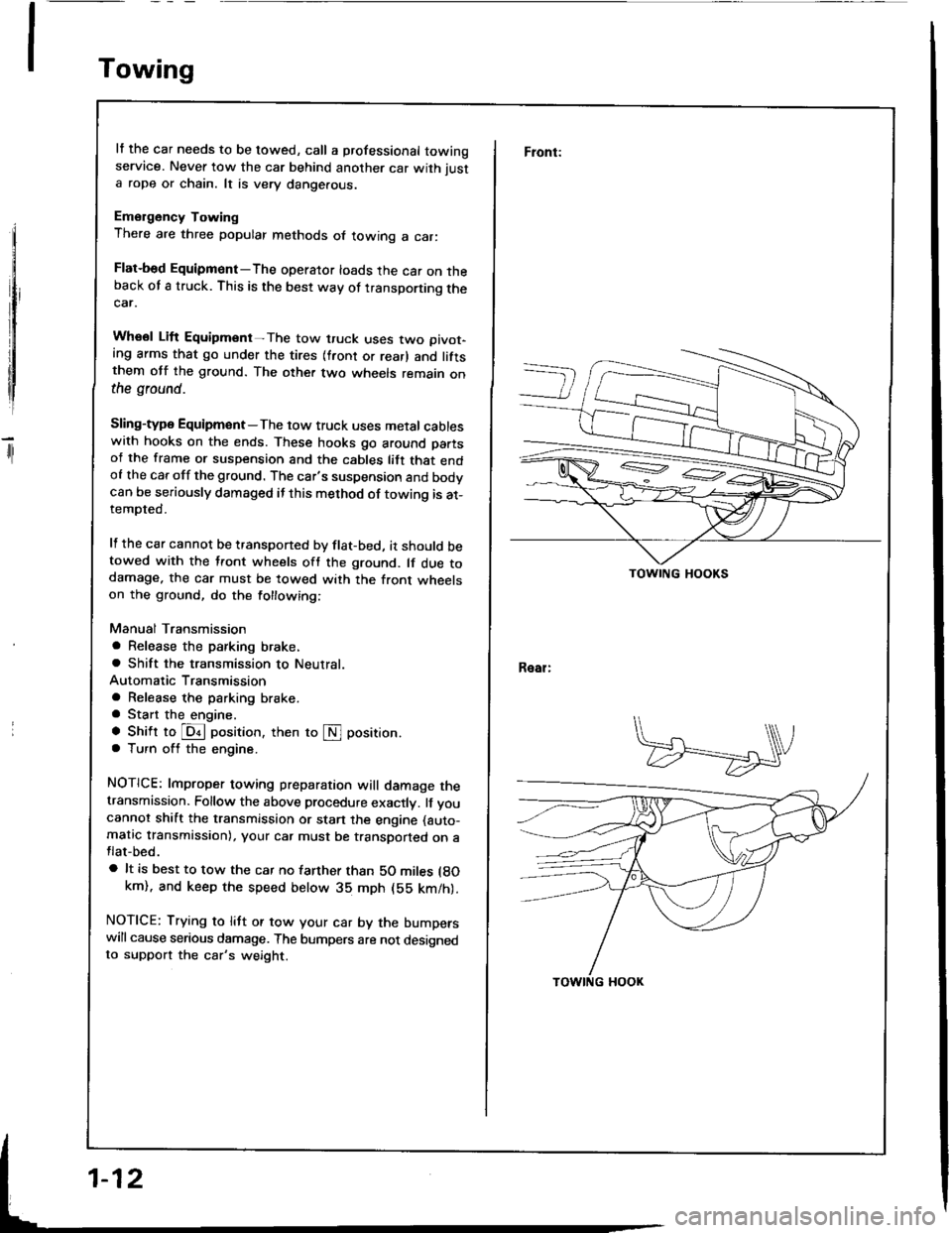
Front:
Real:
TOWING HOOKS
Page 31 of 1413
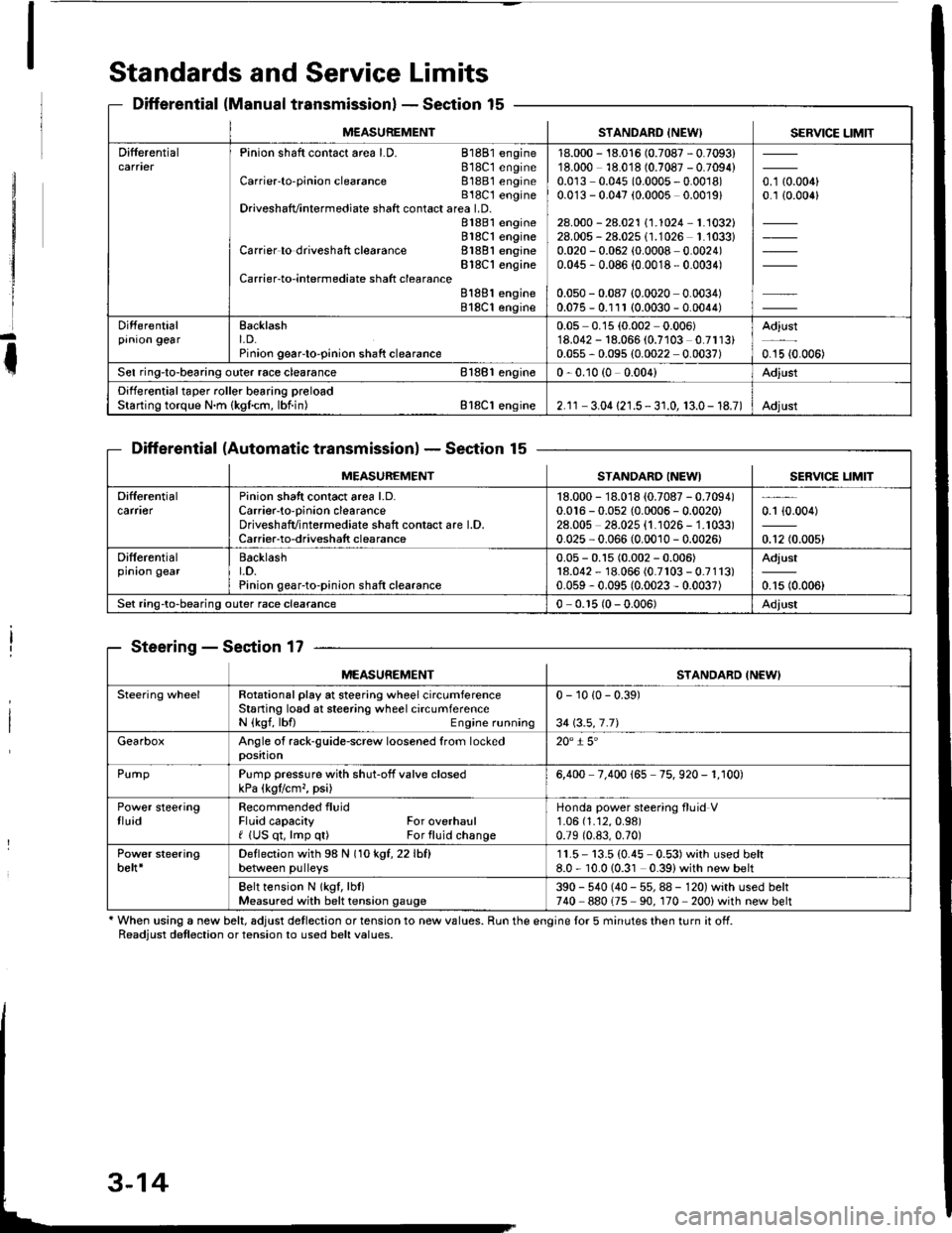
Standards and Service Limits
Differential (Manual transmissionlSection 15
Differential (Automatic transmissionlSection 15
Steering - Section 17
' When using a new belt, adjust detlection or tension to new values. Run the engine lor 5 minutes then turn it off.Readiust detlection or tension to used belt values.
M€ASUREMENTSTANDARD INEW) SERVICE LIMIT
DifferentialPinion shaft contact area LD. 81881 engine818C1 engineCarrier'to-pinion clearance 81881 engineB18C t engineDriveshafvintermediate shaft contact area LD.81881 engine818C1 engineCarrier to driveshaft clearance 81881 engineBlSC'l engineCarrier-to-intermediate shatt clearanceB188l engine818C1 engine
18.000 - 18.016 (0.7087 - 0.7093)18.000 18.018 (0.7087 - 0.7094)0.0r3 0.045 (0.0005 - 0.0018)0.0'13 - 0.047 (0.0005 0.0019)
28.000 - 28.021 \1.1024-1.1032128.005 - 28.025 (1.1026 1.'1033)0.020 - 0.062 (0.0008 0.0024)0.045 , 0.086 {0.0018 - 0.0034)
0.050 - 0.087 (0.0020 0.0034)0.075 - 0.111 (0.0030 - 0.0044)
o. t aron,0.1 {0.006}
Differentialprnron gearEacklasht. D.Pinion geaFto-pinion shaft clearance
0.05 0.15 (0.002 0.006)'18.042 - 18.066 (0.7103 0.7113)0.055 - 0.095 (0.0022 0.0037)
Adjust
0.15 {0.006)
Sel ring-to-bearing outer race clearance 81881 engin€0 - 0.10 (0 0.004)Adjust
Differential taper roller bearing preloadStarting torque N.m {kgfcm, lbf.in) Bl8Cl engine2.1r - 3.04 {21.5 - 3 r.0, 13.0- 18.7)Adjust
MEASUREMENTSTANDARO INEWISERVICE LIM]T
Difterentialcarfl€rPinion shatt contact area l.D.Carrier-to-oinion clearanceDriveshafvintermediate shaft contact are l.D.Carrier-to-driveshatt clearance
18.000 - 18.018 {0.7087 - 0.7094)0.016 - 0.052 {0.0006 - 0.0020)28.00s 28.025 {1.1026 - 1.1033)0.025 - 0.066 (0.0010 - 0.0026)
0.1 {0.004)
0.12 (0.005)
Differentialprnron gearBacklasht.D.Pinion gear-to-pinion shaft clearance
0.05 - 0.15 (0.002 - 0.006)18.042 - 18.066 (0.7r03 - 0.7113)0.059 - 0.095 (0.0023 - 0.0037)
Adjust
0.15 (0.006)
Set ring-to-bearing outer race clearance0 - 0.r5 (0 - 0.006)Adjust
MEASUREMENTSTANDARD INEWI
Steering wheelRotational play at steering wheel circumferenceStaning losd at steering wheel circumferenceN {kgf, lbfl Engine running
0 - 10 {0 - 0.39)
34 \3.5,7.71
GearboxAngle of rack-guide-screw loosened from lockedposition20" i 5'
PurnpPump pressure with shut-off valve closedkPa (kgtlcm,, psi)6,400 7.400 165 75. 920 - 1. r00)
Power steeringtluidRecommended fluidFluid capacity For overhaulf (US qt, lmp q0 For fluid change
Honda power steering fluid V1.06 (1.12,0.98)
0.79 (0.83,0.70)
Power steeringbelt*Deflection with 98 N (1okgt,22lhfl
between pulleys11.5- 13.5 (0.45 0.53)with used belt8.0 - 10.010.31 0.39)with new belt
Belt tension N lkgf, lbl)Measured with belt tension gauge390 - 540 (40 - 55, 88 - 120) with used belt740 880175 90. 170 200) with new belt
Page 32 of 1413
![HONDA INTEGRA 1994 4.G Workshop Manual MEASUFEMENTSTANDARD I]{EWI
a gnmentCamber FrontRgarCaster FrontTotaltoe FrontRearFront whe€lturning angle Inward whe€lOutwsrd wh€el
-0. 10 1 1.-0 15 l$igl1. 10�r t"0i2(010.081rN 3:i (0.121ff HONDA INTEGRA 1994 4.G Workshop Manual MEASUFEMENTSTANDARD I]{EWI
a gnmentCamber FrontRgarCaster FrontTotaltoe FrontRearFront whe€lturning angle Inward whe€lOutwsrd wh€el
-0. 10 1 1.-0 15 l$igl1. 10�r t"0i2(010.081rN 3:i (0.121ff](/img/13/6067/w960_6067-31.png)
MEASUFEMENTSTANDARD I]{EWI
a gnmentCamber FrontRgarCaster FrontTotaltoe FrontRearFront whe€lturning angle Inward whe€lOutwsrd wh€el
-0. 10' 1 1.-0' 15' l$igl1. 10'�r t"0i2(010.081rN 3:i (0.121ff)36' 0o' r 2'30. 30'
A1lc€lbearingEnd playFrontRoaa0 - 0.05 (0 - 0.002)0 - 0.05 {0 - 0.002}
Rim runout (Aluminum wheel) AxialRadialRim runout isteelwhgel) AxialRadisl
STANDARD INEWISEBVICE UMIT
0 - 0.7 {0 - 0.03)0 - 0.7 (0 - 0.03)0 - 1.0 {0 - 0.0{)0 - 1.0 (0 - 0.04)
2.0 (0.08)
1.5 (0.06)
2.0 (0.081
r.5 (0.061
SuspensionSestion 18
BrakeSection 19
Air ConditioningScction 22
.1: When using a new bek, adjust dellection or tension to new values. Run the engine tor 5 minules ihen turn it ott.
Readiust detlection or tension to lsed beh values.'2: 81881 engine'3: 818C1 engine
Unit of length: mm {in)
MEASUREMENTSTANDARD {NEWI
trrling brakePlay in strok€ at 200 N {20 kgf, 44 lbt)lever lorceTo b€ lockod when pulled 6 -10
nolchsa
; oot brake,adalPedal heighl lwith floor mat removod)
Free play
M/T160 (6.30)
155 (6.50)
1-5(0.04-0.20)
Vaster cylinderPiston-to-oushrod clearance0 - 0.4 (0 - 0.2)
f,,s4 brakeOisc thickness FrontRe6rDisc runout FrontR6arDisc parallolism Front and rear
Pad lhickness FrontRoar
STANDARD INEWISERVICE LIM]T
20.9 - 21.1 t0.82 - 0.83t8.9 - 9.1 {0.35 - 0.36)
9.5 - 10.5 {0.37 - 0.41}7.0- 8.0 {0.27 - 0.31)
19.0 (0.75)
8.0 (0.31)
0.10 (0.004)
0.r0 (0.00a)
0.015 (0.0006t
r.6 (0.06)
1.6 (0.06)
MEASUREMENTSTANDABO IT{EWI
Ar conditioningLubricant capacity mf (ll oz) Cond€nserEvaporatorLine or hoseReceiverLubricant type: NO-OlL8 {P/N 38899 - PR7 - A0l)
25 (5/6)
40 t1 1/3)10 (lBt
10 (1/31
CompressorLubricant capacity m{ (ll oz}Lubricant tvge: ND-O|L8 (P/N 38899 - PR7 - A01)Stator coil resistance at 68'F (20'C) 0Pulley-to-pressure plate clearance
140';u (4-23';")
3.4- 3.80.5 r 0.15 {0.02 r 0.006)
Compressorb€h'rDetlection with 98 N (10 kgf, 22 lbf)betlveen pulleys
7.5 - 9.5 {0.30 - 0.37)with used b€lt*'�8.5 - 10.5 {0.33 - 0.41}with t/sod belt'35.0 - 7.0 {0.20 - 0.28) with new belt
Belt t€nsion N (kgf, lbl)Measured with belt lension gauge390 - 540 {r0 - 55, 88 - 120} with used beh*'�340 - 490 {35 - 50, 77 - 110} with used belt*3740 - 880 {75 - 90, 170 - 200) with new belt
3-15
Page 34 of 1413
![HONDA INTEGRA 1994 4.G Workshop Manual Design Specifications
]TEMMETRICENGLISHNOIES
: vENSTONSOveralllength 3 DOOR
4 DOOR
Ov€rallWidth
Overall Height 3 DOOR
4 DOOR
Wheelbase 3 DOOR
4 DOOR
Track F/R
Ground Clearance
Seating Capacity
4.38 HONDA INTEGRA 1994 4.G Workshop Manual Design Specifications
]TEMMETRICENGLISHNOIES
: vENSTONSOveralllength 3 DOOR
4 DOOR
Ov€rallWidth
Overall Height 3 DOOR
4 DOOR
Wheelbase 3 DOOR
4 DOOR
Track F/R
Ground Clearance
Seating Capacity
4.38](/img/13/6067/w960_6067-33.png)
Design Specifications
]TEMMETRICENGLISHNOIES
:' vENSTONSOveralllength 3 DOOR
4 DOOR
Ov€rallWidth
Overall Height 3 DOOR
4 DOOR
Wheelbase 3 DOOR
4 DOOR
Track F/R
Ground Clearance
Seating Capacity
4.380 mm
4.525 mm
'1,710 mm
1,335 mm
1,370 mm
2,570 mm
2,620 mm
't,475/1,470 mm
150 mm
Four (3 DOOR)
172.1in
178.1 in
67.3 in
52.6 in
101.2 in
103.1 in
5|8.1/57.9 in
Five (4 DOOR)
,rerght (usA)cross V€hicle Weight Rating {GVWR)3,680lbs
'le,ght {CANADA)Gross Vehicls Weight Rating {GVWR)1,670 kg
:\GINEType81881 engine
818C1 engine
Cylinder Arrangement
Bore and Stroke
Displacement
Compression Ratio
81881
818C1
81881
B18C I
81881
B 18C1
81881
818C1
engrne
engane
engrne
engine
engine
engine
engine
engine
L!brication Systom
OilPump Displacement
Wster Pump Displacement
FuelRequired
81881
B18C 1
81881
B 18C1
91881
engrne
engrne
engine
engine
engine
818C1 engine
Water-cooled, 4-stroke DOHC
gasoline engine
Watercooled, 4-stroke DOHC
VTEC gasoline engine
Inline 4-cylinder, transverse
81.0 x 89.0 mm
81.0 x 87.2 mm
1,834 cm3 (mf )
1,797 cm3 (m{)
3.19 x 3.50 in
3.19 x 3.43 in
112 cu-in
110 cu-in
9.2:1
10.0 : 1
Eelt driven, OOHC 4 valve per cylinder
Belt driven, DOHC VTEC
4 valve per cylinder
Forced and wet sump, trochoid pump
50, {53 US qt, 44 lmp qt)/minute'l
71 f {75 US qt, 62 lmp qt)/minute"
140 f (148 US qt, 123 lmp qt)/minute*!
140 f (148 US qt. 123 lmp qt)/minute*'
UNLEADED gasoline with 86 Pump
Octane Numb€r or higher
Premium UNLEADED gasoline wilh
91 Pump Octane Number or higher
STARTERTypo
NormalOutput
NominalVoltage
Hour Rating
Direction of Rotation
Weight
Gear reduction
1.4 kW
12V
30 seconds
Clockwise as viewed lrom g6ar end
3.7 k9 | 8.3lbs
CLUTCHClutch Type
Clutch Facing Area
M/TSingle plate dry, diaphragm spring
Torq!e converter
203 cm'� I 31 sq-in
TRANSMISSIONTransmission Type M/T
Primary Reduction
Synchronized 5-speed forward, 1 reverse
Electronically controlled
4-speed automatic. 1 rcverse
Diract 1 : 1
'1: At 6,000 engine
'2: At 7,600 engine
rpm
rpm
(cont'd)
3-17
Page 35 of 1413
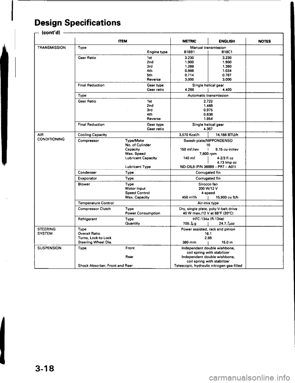
Design Specifications
{cont'd}
lTEMMETRICI€iIGLISHINOTES
TRANSMISSIONTypeEngine typoManual transmission81881 | 818C1
G6ar Ratio 1st2nd3rd4th5thRov€rs€
3.2301.9001.2690.966o.7113.000
3.230r.9(X)1.3601.0340.'t873.000
Fin6l Reduction Gear typeGear ratioSingle helicalge.r4.2664.400
TypeAutomatic transmission
Gear Ratio 'l6t
znd3rd4thRevelse
2.7221.4640.97s0.6381.954
Final R€duction Goar typoGear ratioSingle helic6lgoar4.357
AIRCONDITIONINGCooling Capacity3,570 Kcal/h14,166 BTU/I
Compr6ssor Type/MakeNo. ol CylinderCaPtcityMax. SpsedLubricant C6pacity
Lubricrnt Type
swash-plare/NIPPoNDENSO10150 ml /rcv | 9.15 cu-in/r€v7,600 rpm140 mf | 1-2Bll ozI l.;3 tmp ozND-O|L8 (P/N 38899 - PR7 - A01)
Cond6ns€r TypeCorrugated fin
Evaporator TypeCorrugatod tin
Blower TypeMotor InputSpeed ControMax. Capachy
Sirocco tan200 w12 v4-speed450 m3/h | 15,900 cu lvh
Temperature ControlAirmix type
Compressor Clutch TypePowor ConsumptionDry, singlo plate, poly-V-b€lt driv640 W max./12 V at 68"F {20'C)
Refrigerant TypeOu.ntityHFC-134a (R-134a)
zoo-Ss I 24.7-l.aoe
STEERINGSYSTEMTypeOverall RatioTurns, Lock-to-LockSreering Wheel Dia.
Power assisted, rack and pinion16.12.98380 mm | 15.0 in
SUSPENSIONType Front
Roar
Shock Absorb€r, Front and Rear
Independent double wishbono,coil spring with st6bilizerIndependont double wishbong.coil spring with stabilizerTelescopic, hydraulic nitrogen gas-tilled
3-18
Page 36 of 1413
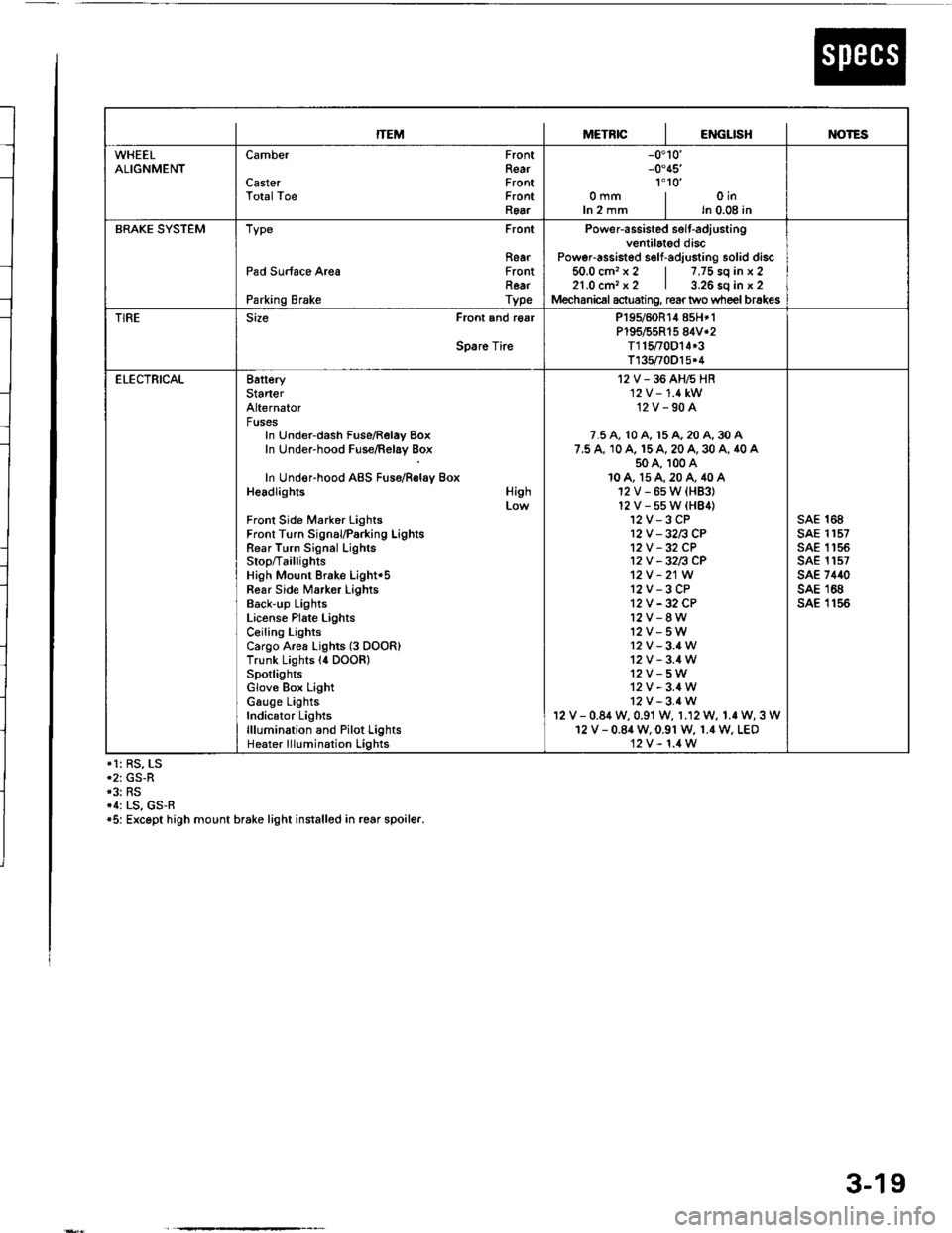
ITEMMETRICIENGLISHIM)TES
WHEELALIGNMENTCamber
CasterTotalToe
FrontRearFrontFrontRear
-0.10'-0.45'�
1'1o'�omm | oinIn 2 mm I ln 0.08 in
BRAKE SYSTEMType Front
RearPad Surface Area FrontRearParking Brake Type
Power-assisted selt-adiustingventilated discPoweFassisted self-adjusting solid discio.u cm. x z | /,/5 so tn x z21.0 cm, x2 | 3.26 sq in x 2Mechanical actuating, rear two wheel brakes
TIRESize Front and r€ar
Spare Tire
P195/60R14 858*1P195/55R15 84V*2T115t0D14*3T135/70O15.4
ELECTRICAL8atteryStarterAlternatorFusesIn Under-dash Fuse/Relay BoxIn Under-hood Fuse/Relay Box
In Under-hood ABS Fuso/Rolay BoxHeadlights
Front Side Marker LightsFront Turn SignauParking LightsRear Turn Signal LighlsStop/Ta illig htsHigh Mount Brake Light'5Fear Side Marker LightsBack-up LightsLiconse Plate LightsCeiling LightsCargo Area Lights (3 DOOR)Trunk Lights l4 DOOR)SpotlightsGlove Box LightGauge LightsIndicator Lightslllumination and Pilot LightsHeater lllumination Lights
High
I2V-36AH6HR'12 V -'1.4 kW12V-90A
7.5 A, 10 A, 15 A, 20 A, 30 A7.5 A, 10 A. 15 A, 20 A, 30 A, 40 A50 A, 100 A10A, 15A,20A,40A12V-6sW{HB3}12V-55W(HB4)12V-3CP12V -32n CP12V -32 CP12V -32n CP12V -21W
12V-3CP12V -32 CP12V-8W12V-5W12v-3.4W12V-3.4W12V-5W12V-3.4W12V-3.4Wv - 0.84 w, 0.91 w, 1.12 W, 1.r W, 3 W12 V - 0.84 W. 0.91 W, 1.4 W. LEO12V-1.4W
sAE 168sAE 1157sAE 1 '�t 55sAE 1157sAE 7440sAE 168sA€ 1156
*1: RS, LS*2: GS-R*3: RS*1: LS, GS-R*5: Except high mount brake light installed in rcar spoiler.
3-19