Wiring HONDA INTEGRA 1994 4.G Workshop Manual
[x] Cancel search | Manufacturer: HONDA, Model Year: 1994, Model line: INTEGRA, Model: HONDA INTEGRA 1994 4.GPages: 1413, PDF Size: 37.94 MB
Page 4 of 1413
,,
SUPPLEMENTAL RESTRAINT SYSTEM (SRS}
The Integra SRS includes a driver's airbag, located in the steering wheel hub. ln addition, all mod€ls excepi tna
Rs model for canada have a front passenger's airbsg located in the dashboard above the glove box, InformaUon
necessary to safely service the SRS is included in this servica Manual. ltems marked with an sstorisk (r) on thr
contents page include, or are located near, SRS components. Servicing. disassembling or roplacing thea6 ltems
will require special precautions and tools, and should thoreiore be done by an authorhed Acura dealer.
' To avoid rondering ths sRS inoporativo, which could lard to porronll Injury or darth In thc cvant ot. r.yr.
trontal collision, all sRs sorvico work must be pcrformcd by !n ruthorizcd Acu.! daerrr,
' lmpTopor 3orvica proceduroa, including inco.roct r.movd r d Installation of tha SRS, could Lld to pc[onc Inlu-
ry caussd by unintsntional activation ot tho airbags.
' All sRs oloctrical wiring harnoa$! aro coverod with yallow In3ulatlon, Rcbtcd componcnts arc bcrtad In tha
stoering Golumn, front console, dsrhboa.d, and darhboard lowor plnol, lnd in thc d$hbolrd abovc tha gaov!
bor. Do not uas oloctdcal te$ oquipmont on thaaa citcuhs.
NoTE: The original radio has a coded thett protection circuit. Be sure to get the customer's code numb6r b€lore* disconnecting the battery.
- removing the No. 32 (7.S A) fuse Jrom the undsr-hood fuse/relay box.
- removing the radio.
After service, reconnect power to the radio and turn it on. When the word ,,CODE,, is displayed, enter the cus_
tomer's 5-digit code to restore radio oDerauon.
Page 11 of 1413
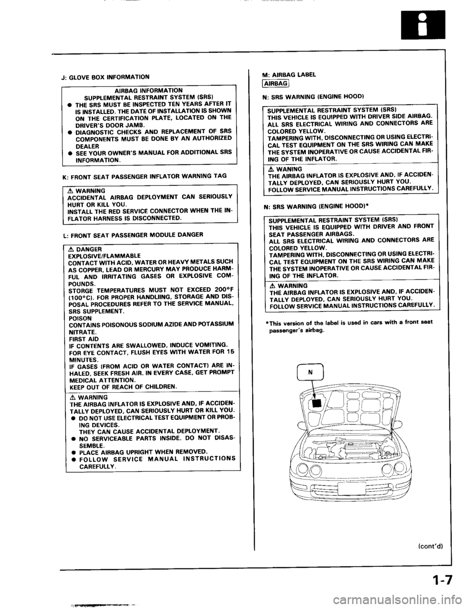
J: GLOVE BOX INFORMATIOf{
AIBBAG INFORMANO
SUPPLEMENTAL RESTiAINT SYSTEM (SRS)
. THE SRS MUST BE INSPECTED TEN YEARS AFTER IT
IS INSTALLED. TI{E DATE OF INSTALLATION IS SHOWN
ON THE CERTTFICATION PLATE, LOCATED ON THE
DRIVER'S DOOR JAMB.
. DIAGNOSTIC CHECKS AND REPLACEMENT OF SNS
COMPONENTS MUST BE DONE BY AN AUTHORIZED
DEALER
. SEE YOUR OWNER'S MANUAL FOR AODITIONAL SRS
INFORMATION.
K: FRONT SEAT PASSENGER INFLATOR WARNING TAG
A WARNING
ACCIDENTAL AIRBAG DEPLOYMENT CAN SERIOUSLY
HURT OR KILL YOU.
INSTALL THE RED SERVICE CONNECTOR WHEN THE IN-
FLATOR HARNESS IS DISCONNECTED
L: FRONT SEAT PASSENGER MODULE DANGER
A DANGER
EXPLOSIVE/FLAMMABLE
CONTACT WITH ACID, WATER OR HEAVY METALS SUCH
AS COPPER. LEAD OR MERCURY MAY PRODUCE HARM'
FUL AND IRRITATING GASES OR EXPLOSIVE COM.
POUNDS.
STORGE TEMPERATURES MUST NOT EXCEED 2OOOF
tlOO"CI. FOB PROPER HANDLIING, STORAG€ AND DIS-
POSAL PROCEDURES REF€B TO THE SERVICE MANUAL,
SBS SUPPLEMENT.
POTSON
CONTAI'\'S POISONOUS SODIUM AZIOE AND POTASSIUM
NITRATE.
FIRST AID
IF CONTENTS ARE SWALLOWED, INDUCE VOMITING.
FOR EYE CONTACT, FLUSH EYES WITH WATER FOR 15
MINUTES.
IF GASES (FROM ACID OR WATER CONTACT) ARE IN.
HALED, SEEK FRESH AIR. IN EVERY CASE. GET PROMPT
MEDICAL ATTENTION.
KEEP OUT OF REACI.I OF CHILDREN.
A' WARNING
THE AIRBAG INFLATOR IS EXPLOSIVE AND. IF ACCIDEN-
TALLY DEPLOYEO, CAN SERIOUSLY HURT OR KILL YOU.
. DO NOT USE ELECTRICAL TEST EOUIPMENT OR PROB.
ING DEVICES.
THEY CAN CAUSE ACCIOENTAL DEPLOYMENT.
. NO SERVICEAALE PABTS INSIDE. OO NOT OISAS-
SEMBLE.
. PLACE AIRBAG UPFIGHT WHEN REMOVED.
. FOLLOW SERVICE MANUAL INSTRUCTIONS
CAREFULLY.
fi{lHfiFe*% _
1-7
M: AIRBAG LABEL
AIRBAG
N: SRS WARNING IENGINE HOODI
SUPPLEMENTAL RESTRAINT SYSTEM (SBSI
THIS VEHICLE IS EOUIPPED WITH DRIVER SIDE AIRBAG.
ALL SRS ELECTRICAL WIRING AND CONNECTORS ARE
COLORED YELLOW.
TAMPERING WITH, DISCONNECTING OR USING ELECTRI-
CAL TEST EOUIPMENT ON TI{E SRS WIRING CAN MAKE
THE SYSTEM INOPERATIVE OB CAUSE ACCIOENTAL FIR'
ING OF THE INFLATOR.
A. WANING
THE AIRBAG INFLATOR IS EXPLOSIVE AND, IF ACCIDEN-
TALLY DEPLOYED, CAf{ SERIOUSLY HURT YOU'
FOLLOW SERVICE MANUAL INSTRUCTIONS CAREFULLY.
SUPPLEMENTAL RESTRAINT SYSTEM {SRSI
THIS VEI{ICLE IS EOUIPPED WITH DRIVER ANO FRONT
SEAT PASSENGER AIRBAGS.
ALL SRS ELECTRICAL WIRING AND CONNECTORS ARE
COLORED YELLOW.
TAMPENING WITI{, DISCONNECTING OR USI G ELECTRI'
CAL TEST EOUIPMENT ON THE SRS WIRING CAN MAKE
THE SYSTEM INOPERATIVE OR CAUSE ACCIDENTAL FIB'
ING OF THE INFLATOB.
A WABNING
THE AIRBAG INFLATOR IS EXPLOSIVE AI{O, IF ACCIDEN-
TALI-Y DEPLOYED, CAN SEBIOUSLY HURT YOU'
FOLLOW SERVTCE MANUAL INSTRUCTIONS CAREFULLY.
N: SRS WARNING IENGINE HOODIi
'This vorsion
passonger's
ol tho labol is u36d in cs.t with a front soat
airbag.
{cont'd)
Page 48 of 1413
Engine Removal/lnstallation
@a Make sure jacks and safety stands aro placed ploper-
ly and hoisl brackots arg attachod to the correct po-
sitions on tho engine (se€ ssction 1).
a Mak€ sure tho car willnot roll off stands and tallwhile
you are wotking under it'
CAUTION:
a Use fendet covals to avoid damaging painted
sudaces.
r Unspecified itsms alo common
a Unplug tho widng connectots carefully while holding
the couplor and tha connector portion to avoid
oamage.
a Mark all wiring and hoses to avoid misconnection.
Also, be sulo that thsy do not contact other wiring
or hoses, or interfere with oth€l parts.
NOTE: Anti-theft radios have a coded theft ptotection
circuit. Be sure to get the customer's code number beJore
- Disconnecting the batterY.
- Removing the No. 32 (7.5 A) fuse from the under-
hood tuse/relay box.- Removing the radio
Atter service, reconnect power to the radio and turn it
on. When the word "CODE" is displayed, enter the cus-
tomer's 5-digit code to restore radio operataon.
1. Remove the hood (see section 2O).
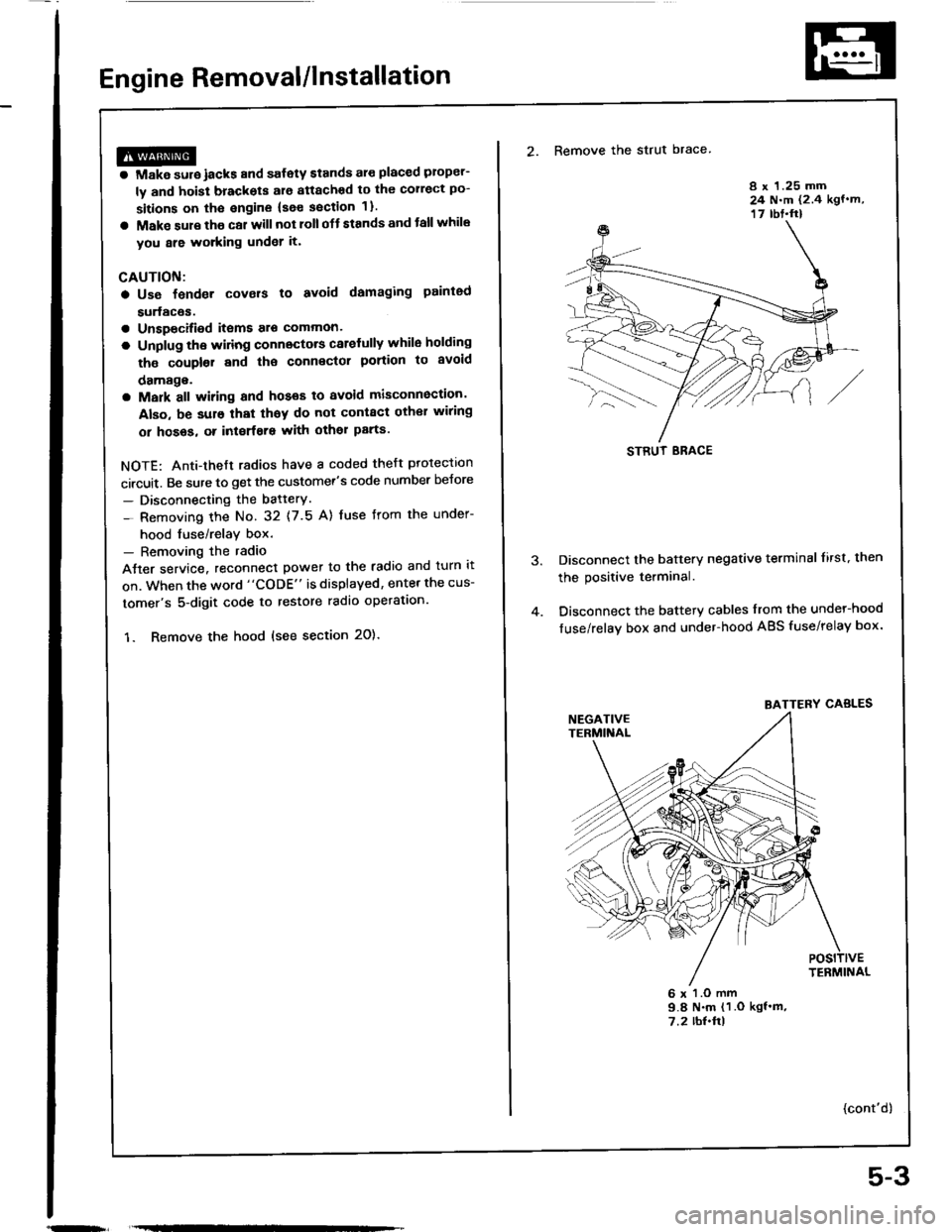
2. Remove the strut brace
8 x 1.25 mm24 N.m (2.4 kgf.m,17 rbt.ft)
Disconnect the battery negative terminal lirst. then
the positive terminal.
Disconnect the battery cables from the undel-hood
fuse/relay box and under-hood ABS fuse/relay box.
6 x l.O mm9.8 N.m (1 .O kgf'm,7.2 rbl.ftl
{cont'd)
STRUT ERACE
BATTERY CABLES
5-3
Page 237 of 1413
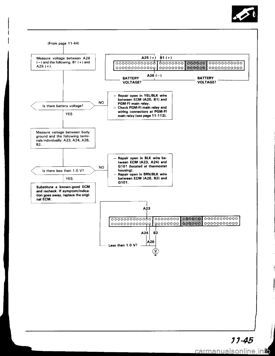
(From page 1l-44)
Measure voltage between 426
{- ) and the following: B'1 (+ } andA25 {+ t.
- Ropsir opon in YEL/BLK wirobotwoon ECM (425, 81l andPGM-FI m6in relay.- Chock PGM-FI main rclay andwiring connectors at PIGM-FImain.olay (soe psg6 11-1121.
ls there battery voltage?
Measure voltage between bodyground and the tollowing termi-nals individually: A23. A24, A26,42.
- noprir opon in BLK wit. b6-twson ECM 1A23, A24l andG'101 {locatod al th6.mostathousingl.Repair opon in BRN/BLK witebotweon ECM (A26, B2l andGl0r.
ls there less then 1.0 V?
Substitut6 r known{ood ECM
and r6chock. lf symptom/indica-tion goos away, roplaco tho origi-nal ECM.
BATTERYVOLTAGET
ooooooooooo
oooooooooooooooooooooo
ooooooooooo
oooooooo
ooooooo
L€ss than 1.0 V?
11-45
Page 441 of 1413
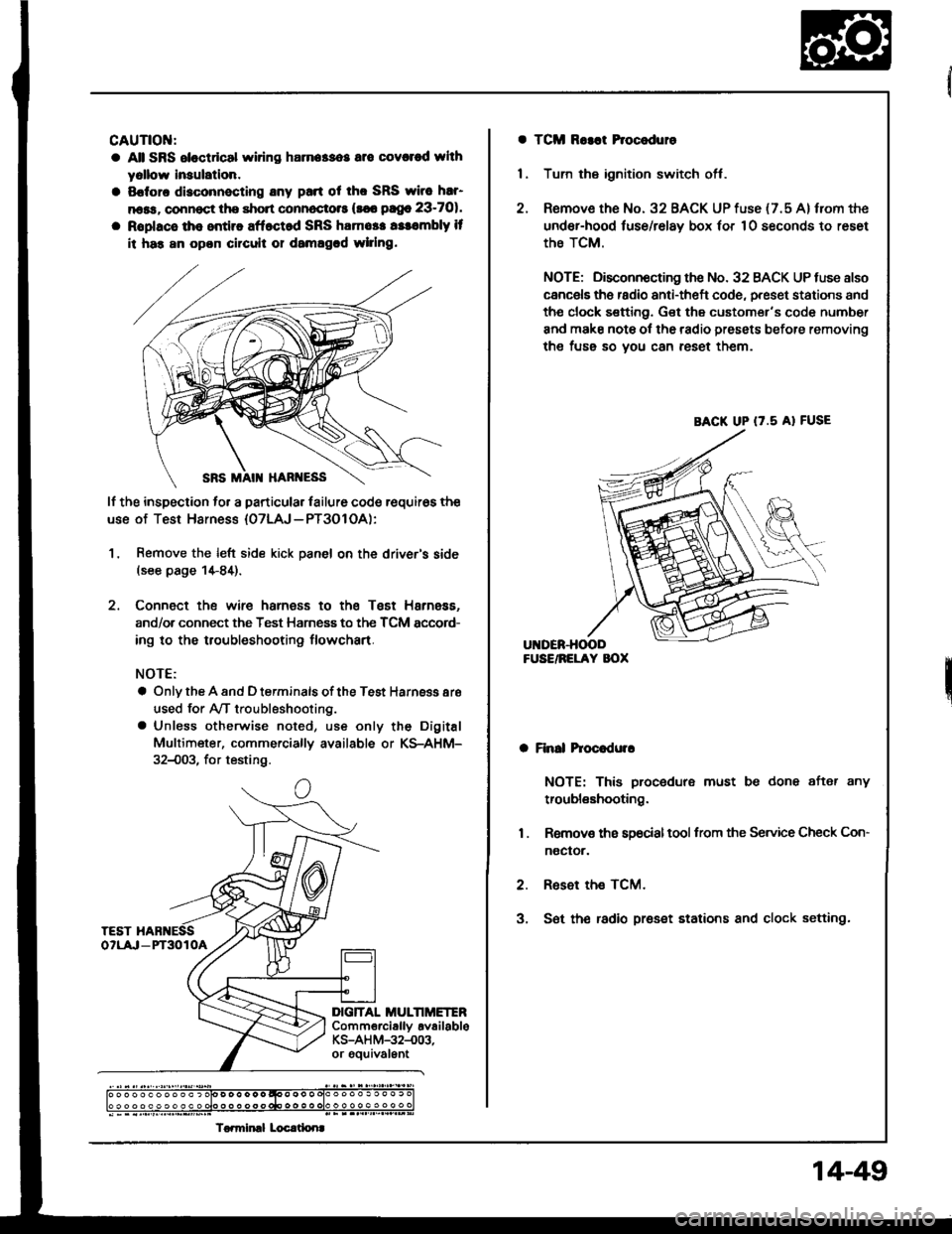
CAUTIOI{:
a All SRS eloctdcal wiring harna$os are covcred whh
yollow lnaulation.
a Sofora disconnecting any pan ot tho SRS wirc har'
n6ss, connoct the short connoctots (s€6 pago 23-701.
a Roplacs tho entiro aff.ct d SRS ham6t. rssombly it
ii has an opon circuil or damagcd wlrlng.
lf the inspection to. a particular lailure code requir6s the
use of Test Harness {07LAJ - PT3O1 OA):
1, Remove the left side kick panel on the driver's side(see page 1+84).
2. Connect the wire harness to the Tsst Harness.
and/or connect the Test Harness to the TCM sccord-
ing to the troubleshooting flowchart.
NOTE:
a Only the A and D terminals of the Test Harnsss aro
used for Ay'T troubleshooting.
a Unless otherwise noted, use only the Digital
Multimeter, commerciallv available or KS-AHM-
32{)03, for testing.
c
DIG]TAL MULTIMETERComm€rciallv availableKS-AH M-32-.003,or gouivalEnt
) o o o o o o o o o o ) olo D o o o o o qoo o o o olo o o o o . o o o . c
To.miml Locrtlonr
a TCM Ro3at Procoduro
1 . Tum the ignition switch off.
2. Remove the No. 32 BACK UP fuse {7.5 A} from the
under-hood luse/relay box 'or 10 seconds to reset
the TCM.
NOTE; Disconnocting the No. 32 BACK UP tuse also
cancels ths radio anti-theft code, preset stations and
tho clock sefting. Get the customer's code number
and make note ol the radio presets before removing
the fuss so you can reset them.
a Finll hoc.dulr
NOTE: This procedure must be done after any
troubleshooting.
1 . Removs ths s9ocialtool from the Service Check Con-
noctor.
2. Reset the TCM.
3, S6t th€ radio preset stations and clock setting.
BACK UP (7.5 A} FUSE
14-49
Page 476 of 1413
Transmission Control Module
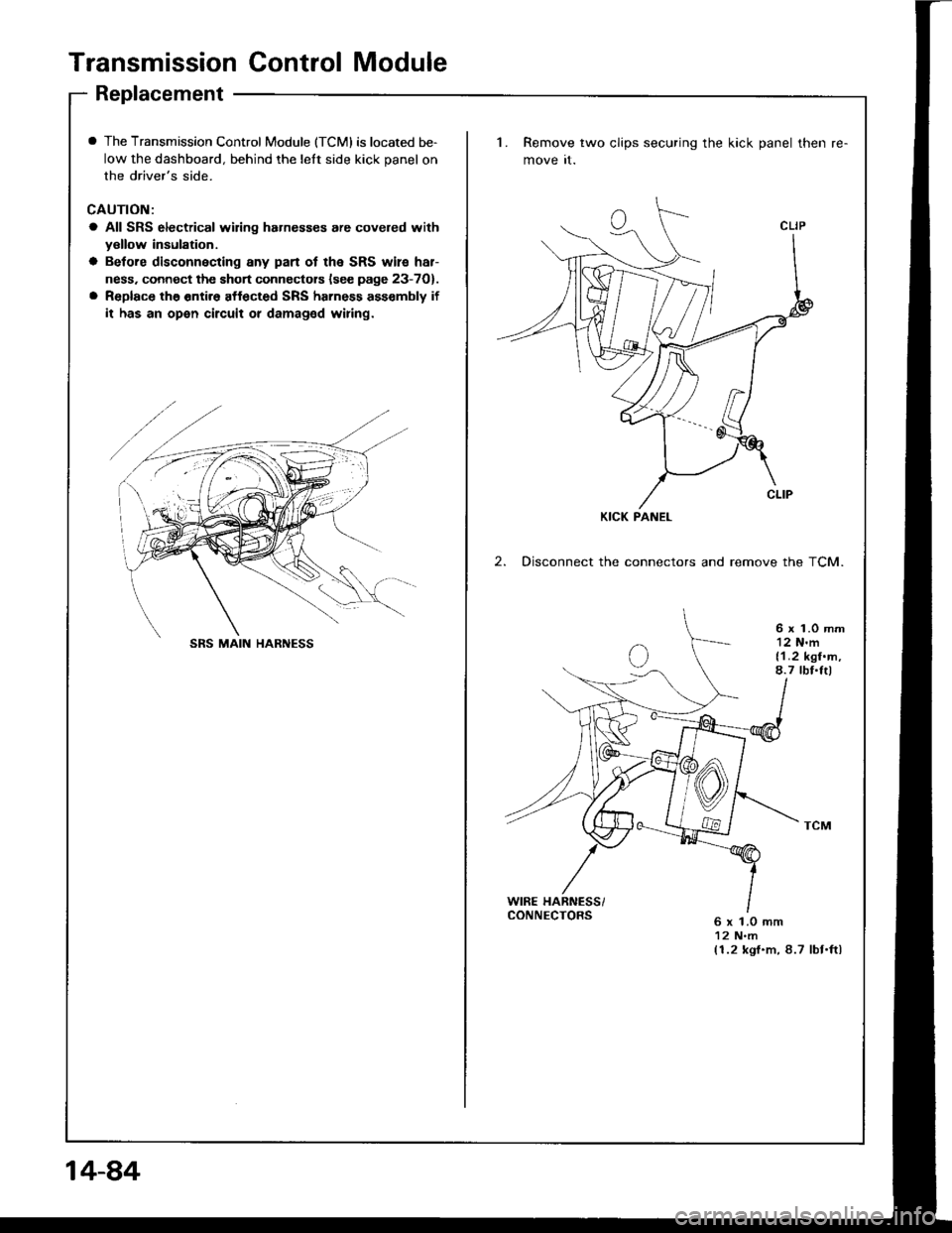
Replacement
I The Transmission Control Module (TCMI is located be-
low the dashboard, behind the lelt side kick panel on
the driver's side.
CAUTION:
a All SRS electrical wiring hahesses are covered withyellow insulation.
a Betore disconnecting any pan ot the SRS wile har-
ness. connect the short connectors lsee page 23-7O).
a Replace the entir6 affected SRS harness ass€mbly if
it has an open circuit or damaged wiring.
1. Remove two clips securing the kick panel then
move it.
2. Disconnect the connectors and remove the TCM.
6 x 1.0 mm12 N'm{1.2 kgf.m,8.7 tbf.Itl
WIRE HARNESS/CONNECTORS6 x 1.0 mm12 N.m(1.2 kgf.m, 8.7 lbt.ftl
KICK PANEL
SRS MAIN HARNESS
14-84
Page 560 of 1413
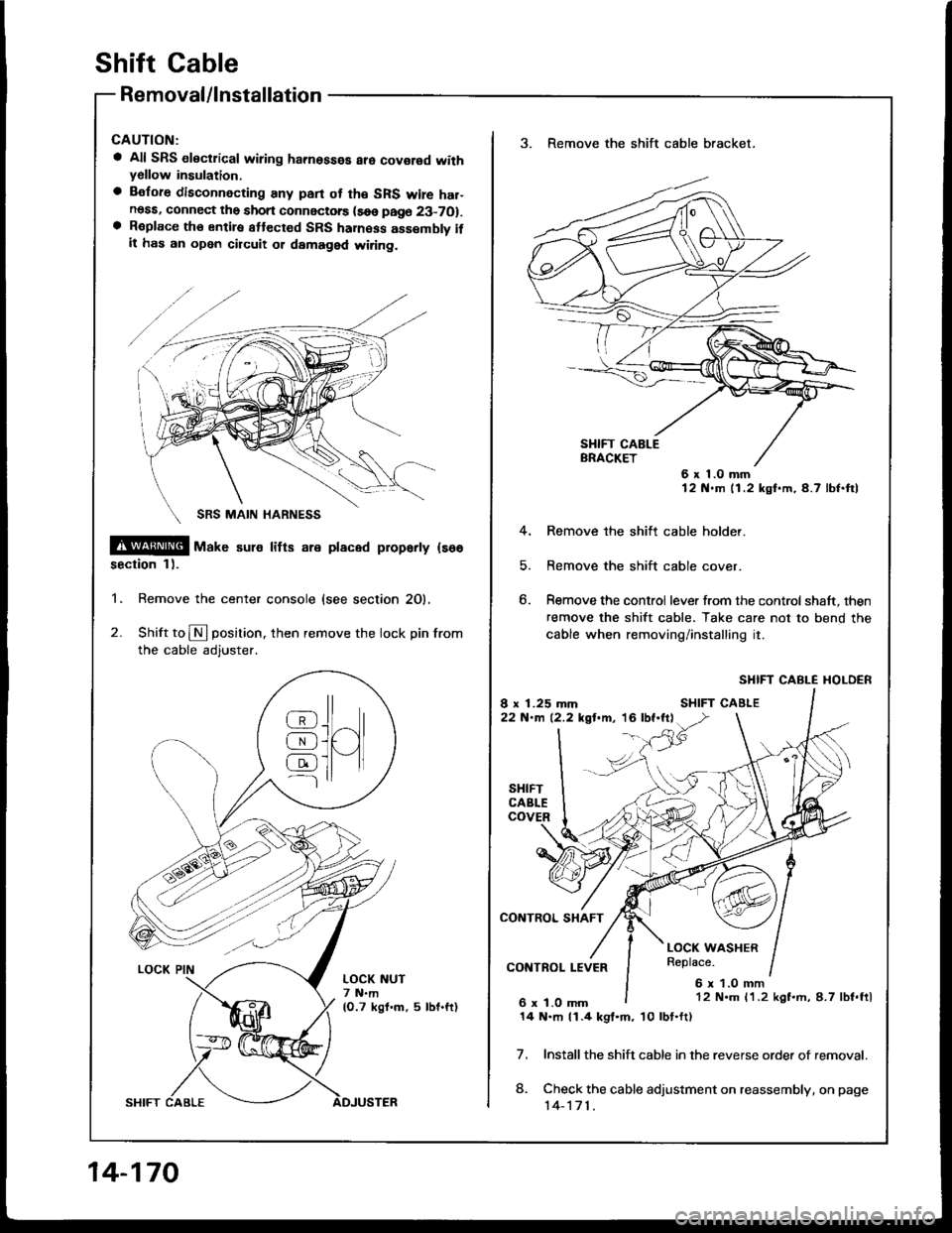
shift cable
Removal/lnstallation
a All SRS electrical wiring hamosses are covor€d withyellow insulation.
a Before disconnecting any pan ot th€ SRS wire har-noss, connect the short connectorc (soe page 23-7O1.a Roplace th€ entiro attect€d SRS haness assembly itit has an open circuit ot damaged wi.ing.
@@[ uar" sul€ litts are placed proparty {so6
section 1).
1. Remove the center console {see section 20).
2. Shift to N position. then remove the lock pin from
the cable adjuster.
@J^ll
AJUI[qJ ]l tl---l
LOCK NUT7 N.m(O.7 kgf.m, 5 lbf.ft)
14-170
3. Remove the shift cable bracket.
6x1.0mm12 N.m 11.2 kgf.m,4.7 lbf.ftl
4. Remove the shitt cable holder.
5. Remove the shift cable cover.
6. Remove the control lever from the control shaft, then
remove the shift cable. Take care not to bend the
cable when removing/installing it.
SHIFT CABLE I{OLDER
Install the shift cable in the reverse orde. of removal.
Check the cable adjustment on reassembly, on page
14-171.
7.
8.
12 N.m 11.2 kgf.rh, 8.7 lbf.ftl
14 N.m 11.4 kgl.m, 10lbt.ft)
Page 561 of 1413
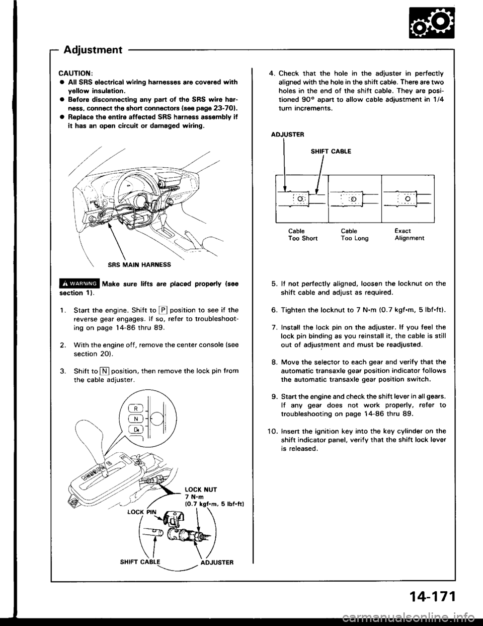
4. Check that the hole in the adiuste. in perfectly
aligned with the hole in the shift cable. There are two
holes in the end of the shitt cable, They are posi-
tioned 9Oo apart to allow cable adiustment in 1/4
lurn Incremenls.
ADJUSTER
CableI oo snonCableToo LongExactAlignment
5. It not perfectly aligned, loosen the locknut on the
shift cable and adjust as required.
6. Tighten the locknut to 7 N.m (O.7 kgf.m, 5lbf.ft).
7. Install the lock pin on the adiuster. lf you feel the
lock pin binding as you reinstall it, the cable is still
out of adjustment and must be readjusted.
8. Move the selector to each gear and verify that the
automatic transaxle gear position indicator tollows
the automatic transaxle gear position switch.
9. Start the engine and check the shift lever in all gea.s.
lf any gea. does not work properly, refer to
troubleshooting on page 14-86 thru 89.
1O. lnsert the ignition key into the key cylinder on the
shift indicator panel, ve.ify that the shift lock lever
is released,
CAUTION:
a All SRS electrical widng harn€sses are covar€d with
yollow insulation.
a Before disconnecting any part of ths SRS wire har-
ness, connect the shon connectors (see page 23-701.
a R€place the entire affected SRS halnass asssmbly it
it has an op€n circuit or damaged wiring.
@ tu"t" sure lifts a.e placed properly ls66
ssction 1).
Start the engine. Stritt to @ position to see if the
reverse gear engages. lf so, refer to troubleshoot-
ing on page 14-86 thru 89.
Wilh the engine off, remove the center console {see
section 20).
Shilt to N position. then remove the lock pin from
the cable adjuster.
'1.
/
''fidlfr
I
t+@
\/ \
CABLE-.'.-_--l../ADJUSTER
]H
@
@
@
Adjustment
14-171
Page 562 of 1413
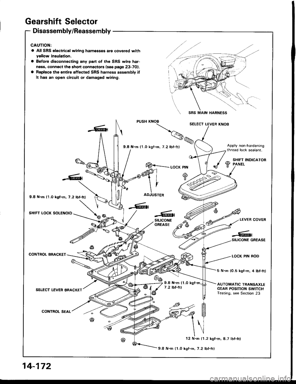
Gearshift Selector
Disassembly/Reassembly
CAUTION:
a All SRS electrical wiing haln€ssss are covered withy6llow insulation.
a 8€fore disconnecting 8ny pan of the SRS wire har-
neaa. connOct th6 short connectors (sse page 23-701.
a Roplace the entire affected SRS hahess assembly if
il has an opon circuit or damaged wiring.
9.8 N.m {1.O kgf.m, 7.2 lbf.frl
SHIFT LOCK SOLENOID
CONTROL BRACKET
SELECT LEVER BRACKET
CONTROL SEAL
SRS MAIN HARNESS
[E--__ rocK ptN
ADJUSTER
-6{stLtcoNEGREASEe-LEVER COVER
LOCK PIN ROD
-#qSILICONE GREASE
@6
5 N.m (0.5 kgt.m, 4 lbt.ftl
AUTOMATIC TRANSAXLEGEAR POSITION SWITCHTesting, see Section 23
9.8 N.m (1.0
7 .2 tbt.ltl
12 N.m (1.2 kgf.m, 8.7 lbf.ftl
9.8 N.m 11.0 kgf'm,7.2 lbf.ftl
14-172
Page 563 of 1413
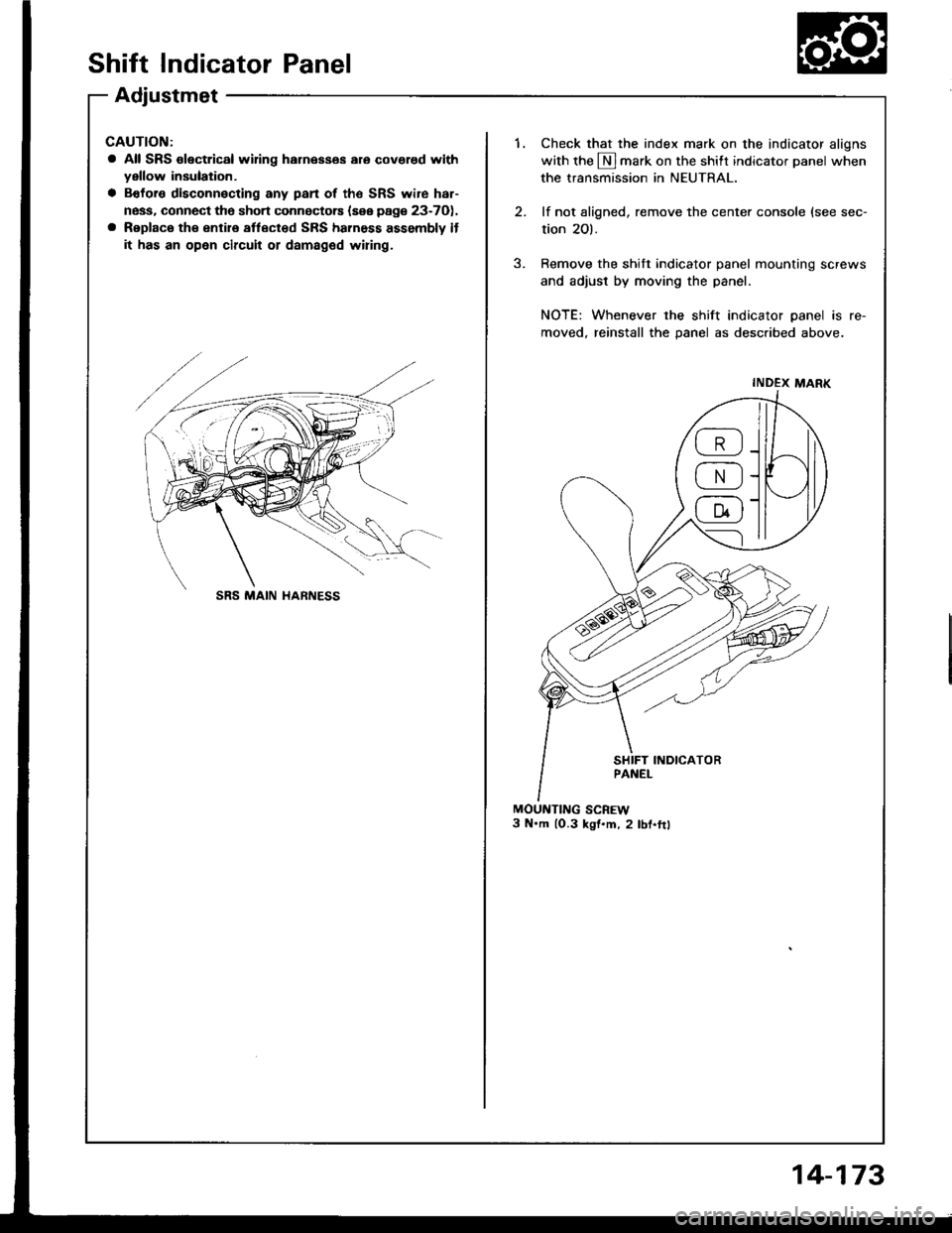
Shift Indicator Panel
Adjustmet
CAUTION:
a All SRS olectrical wifng harnesses aro covered withyellow insulation.
a Bofors disconnecting any pan of the SRS wire har-
ness, connect tho sho.t connectors {sse page 23-7O),
a Replace the entire aflect€d SRS harness assembly if
it has an open circuit or damaged wiring,
1.Check that the index mark on the indicator aligns
with the N]mark on the shift indicator panel when
the transmission in NEUTRAL.
lf not aligned, remove the center console (see sec-
tion 2O).
Remove the shift indicator panel mountinq screws
and adjust by moving the panel.
NOTE: Whenever the shift indicator panel is re-
moved, reinstall the panel as described above.
MOUNTING SCREW3 N'm lO.3 kst.m, 2 lbf.ftt
INDEX MARK
@
@
@
SRS MAIN HARNESS
14-173