cks HONDA INTEGRA 1994 4.G Workshop Manual
[x] Cancel search | Manufacturer: HONDA, Model Year: 1994, Model line: INTEGRA, Model: HONDA INTEGRA 1994 4.GPages: 1413, PDF Size: 37.94 MB
Page 11 of 1413
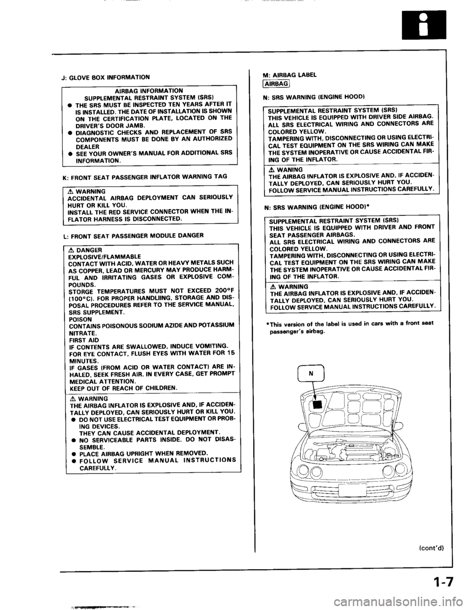
J: GLOVE BOX INFORMATIOf{
AIBBAG INFORMANO
SUPPLEMENTAL RESTiAINT SYSTEM (SRS)
. THE SRS MUST BE INSPECTED TEN YEARS AFTER IT
IS INSTALLED. TI{E DATE OF INSTALLATION IS SHOWN
ON THE CERTTFICATION PLATE, LOCATED ON THE
DRIVER'S DOOR JAMB.
. DIAGNOSTIC CHECKS AND REPLACEMENT OF SNS
COMPONENTS MUST BE DONE BY AN AUTHORIZED
DEALER
. SEE YOUR OWNER'S MANUAL FOR AODITIONAL SRS
INFORMATION.
K: FRONT SEAT PASSENGER INFLATOR WARNING TAG
A WARNING
ACCIDENTAL AIRBAG DEPLOYMENT CAN SERIOUSLY
HURT OR KILL YOU.
INSTALL THE RED SERVICE CONNECTOR WHEN THE IN-
FLATOR HARNESS IS DISCONNECTED
L: FRONT SEAT PASSENGER MODULE DANGER
A DANGER
EXPLOSIVE/FLAMMABLE
CONTACT WITH ACID, WATER OR HEAVY METALS SUCH
AS COPPER. LEAD OR MERCURY MAY PRODUCE HARM'
FUL AND IRRITATING GASES OR EXPLOSIVE COM.
POUNDS.
STORGE TEMPERATURES MUST NOT EXCEED 2OOOF
tlOO"CI. FOB PROPER HANDLIING, STORAG€ AND DIS-
POSAL PROCEDURES REF€B TO THE SERVICE MANUAL,
SBS SUPPLEMENT.
POTSON
CONTAI'\'S POISONOUS SODIUM AZIOE AND POTASSIUM
NITRATE.
FIRST AID
IF CONTENTS ARE SWALLOWED, INDUCE VOMITING.
FOR EYE CONTACT, FLUSH EYES WITH WATER FOR 15
MINUTES.
IF GASES (FROM ACID OR WATER CONTACT) ARE IN.
HALED, SEEK FRESH AIR. IN EVERY CASE. GET PROMPT
MEDICAL ATTENTION.
KEEP OUT OF REACI.I OF CHILDREN.
A' WARNING
THE AIRBAG INFLATOR IS EXPLOSIVE AND. IF ACCIDEN-
TALLY DEPLOYEO, CAN SERIOUSLY HURT OR KILL YOU.
. DO NOT USE ELECTRICAL TEST EOUIPMENT OR PROB.
ING DEVICES.
THEY CAN CAUSE ACCIOENTAL DEPLOYMENT.
. NO SERVICEAALE PABTS INSIDE. OO NOT OISAS-
SEMBLE.
. PLACE AIRBAG UPFIGHT WHEN REMOVED.
. FOLLOW SERVICE MANUAL INSTRUCTIONS
CAREFULLY.
fi{lHfiFe*% _
1-7
M: AIRBAG LABEL
AIRBAG
N: SRS WARNING IENGINE HOODI
SUPPLEMENTAL RESTRAINT SYSTEM (SBSI
THIS VEHICLE IS EOUIPPED WITH DRIVER SIDE AIRBAG.
ALL SRS ELECTRICAL WIRING AND CONNECTORS ARE
COLORED YELLOW.
TAMPERING WITH, DISCONNECTING OR USING ELECTRI-
CAL TEST EOUIPMENT ON TI{E SRS WIRING CAN MAKE
THE SYSTEM INOPERATIVE OB CAUSE ACCIOENTAL FIR'
ING OF THE INFLATOR.
A. WANING
THE AIRBAG INFLATOR IS EXPLOSIVE AND, IF ACCIDEN-
TALLY DEPLOYED, CAf{ SERIOUSLY HURT YOU'
FOLLOW SERVICE MANUAL INSTRUCTIONS CAREFULLY.
SUPPLEMENTAL RESTRAINT SYSTEM {SRSI
THIS VEI{ICLE IS EOUIPPED WITH DRIVER ANO FRONT
SEAT PASSENGER AIRBAGS.
ALL SRS ELECTRICAL WIRING AND CONNECTORS ARE
COLORED YELLOW.
TAMPENING WITI{, DISCONNECTING OR USI G ELECTRI'
CAL TEST EOUIPMENT ON THE SRS WIRING CAN MAKE
THE SYSTEM INOPERATIVE OR CAUSE ACCIDENTAL FIB'
ING OF THE INFLATOB.
A WABNING
THE AIRBAG INFLATOR IS EXPLOSIVE AI{O, IF ACCIDEN-
TALI-Y DEPLOYED, CAN SEBIOUSLY HURT YOU'
FOLLOW SERVTCE MANUAL INSTRUCTIONS CAREFULLY.
N: SRS WARNING IENGINE HOODIi
'This vorsion
passonger's
ol tho labol is u36d in cs.t with a front soat
airbag.
{cont'd)
Page 13 of 1413
![HONDA INTEGRA 1994 4.G Workshop Manual Lift and Support Points
Lift
Wh€n heavy 16ar compon€nts such aa susponsion, luel tank, spale tile and hatch ale to
il]iii6iliieigltt in the tuggage area bsfore hoisting. When substantial woight is HONDA INTEGRA 1994 4.G Workshop Manual Lift and Support Points
Lift
Wh€n heavy 16ar compon€nts such aa susponsion, luel tank, spale tile and hatch ale to
il]iii6iliieigltt in the tuggage area bsfore hoisting. When substantial woight is](/img/13/6067/w960_6067-12.png)
Lift and Support Points
Lift
Wh€n heavy 16ar compon€nts such aa susponsion, luel tank, spale tile and hatch ale to
il]iii6iliieigltt in the tuggage area bsfore hoisting. When substantial woight is lemoved from ths
b€ removod, plac6
l€ar ol th€ car, ths
cantor of gravity may chango and can cause the cal to tip folward on the hoist'
NOTE: Since each tire/wheel assembly weighs approximately 14 kg (30 lbs), placing the front wheels in trunk can assist
with the weight distribution.
1. Place the lift blocks as shown
2. Raise the hoist a lew inches (centimeters) and rock the car to be sure it is firmly supported.
3. Raise the hoist to full height and inspect lift points for solid support.
FRONT SUPPORT POINTLIFT BLOCKSBEAR SUPPORT POINT
1-9
Page 35 of 1413
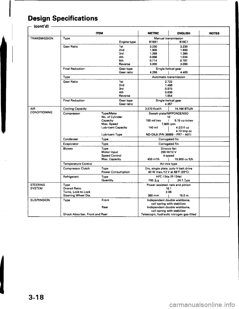
Design Specifications
{cont'd}
lTEMMETRICI€iIGLISHINOTES
TRANSMISSIONTypeEngine typoManual transmission81881 | 818C1
G6ar Ratio 1st2nd3rd4th5thRov€rs€
3.2301.9001.2690.966o.7113.000
3.230r.9(X)1.3601.0340.'t873.000
Fin6l Reduction Gear typeGear ratioSingle helicalge.r4.2664.400
TypeAutomatic transmission
Gear Ratio 'l6t
znd3rd4thRevelse
2.7221.4640.97s0.6381.954
Final R€duction Goar typoGear ratioSingle helic6lgoar4.357
AIRCONDITIONINGCooling Capacity3,570 Kcal/h14,166 BTU/I
Compr6ssor Type/MakeNo. ol CylinderCaPtcityMax. SpsedLubricant C6pacity
Lubricrnt Type
swash-plare/NIPPoNDENSO10150 ml /rcv | 9.15 cu-in/r€v7,600 rpm140 mf | 1-2Bll ozI l.;3 tmp ozND-O|L8 (P/N 38899 - PR7 - A01)
Cond6ns€r TypeCorrugated fin
Evaporator TypeCorrugatod tin
Blower TypeMotor InputSpeed ControMax. Capachy
Sirocco tan200 w12 v4-speed450 m3/h | 15,900 cu lvh
Temperature ControlAirmix type
Compressor Clutch TypePowor ConsumptionDry, singlo plate, poly-V-b€lt driv640 W max./12 V at 68"F {20'C)
Refrigerant TypeOu.ntityHFC-134a (R-134a)
zoo-Ss I 24.7-l.aoe
STEERINGSYSTEMTypeOverall RatioTurns, Lock-to-LockSreering Wheel Dia.
Power assisted, rack and pinion16.12.98380 mm | 15.0 in
SUSPENSIONType Front
Roar
Shock Absorb€r, Front and Rear
Independent double wishbono,coil spring with st6bilizerIndependont double wishbong.coil spring with stabilizerTelescopic, hydraulic nitrogen gas-tilled
3-18
Page 48 of 1413
Engine Removal/lnstallation
@a Make sure jacks and safety stands aro placed ploper-
ly and hoisl brackots arg attachod to the correct po-
sitions on tho engine (se€ ssction 1).
a Mak€ sure tho car willnot roll off stands and tallwhile
you are wotking under it'
CAUTION:
a Use fendet covals to avoid damaging painted
sudaces.
r Unspecified itsms alo common
a Unplug tho widng connectots carefully while holding
the couplor and tha connector portion to avoid
oamage.
a Mark all wiring and hoses to avoid misconnection.
Also, be sulo that thsy do not contact other wiring
or hoses, or interfere with oth€l parts.
NOTE: Anti-theft radios have a coded theft ptotection
circuit. Be sure to get the customer's code number beJore
- Disconnecting the batterY.
- Removing the No. 32 (7.5 A) fuse from the under-
hood tuse/relay box.- Removing the radio
Atter service, reconnect power to the radio and turn it
on. When the word "CODE" is displayed, enter the cus-
tomer's 5-digit code to restore radio operataon.
1. Remove the hood (see section 2O).
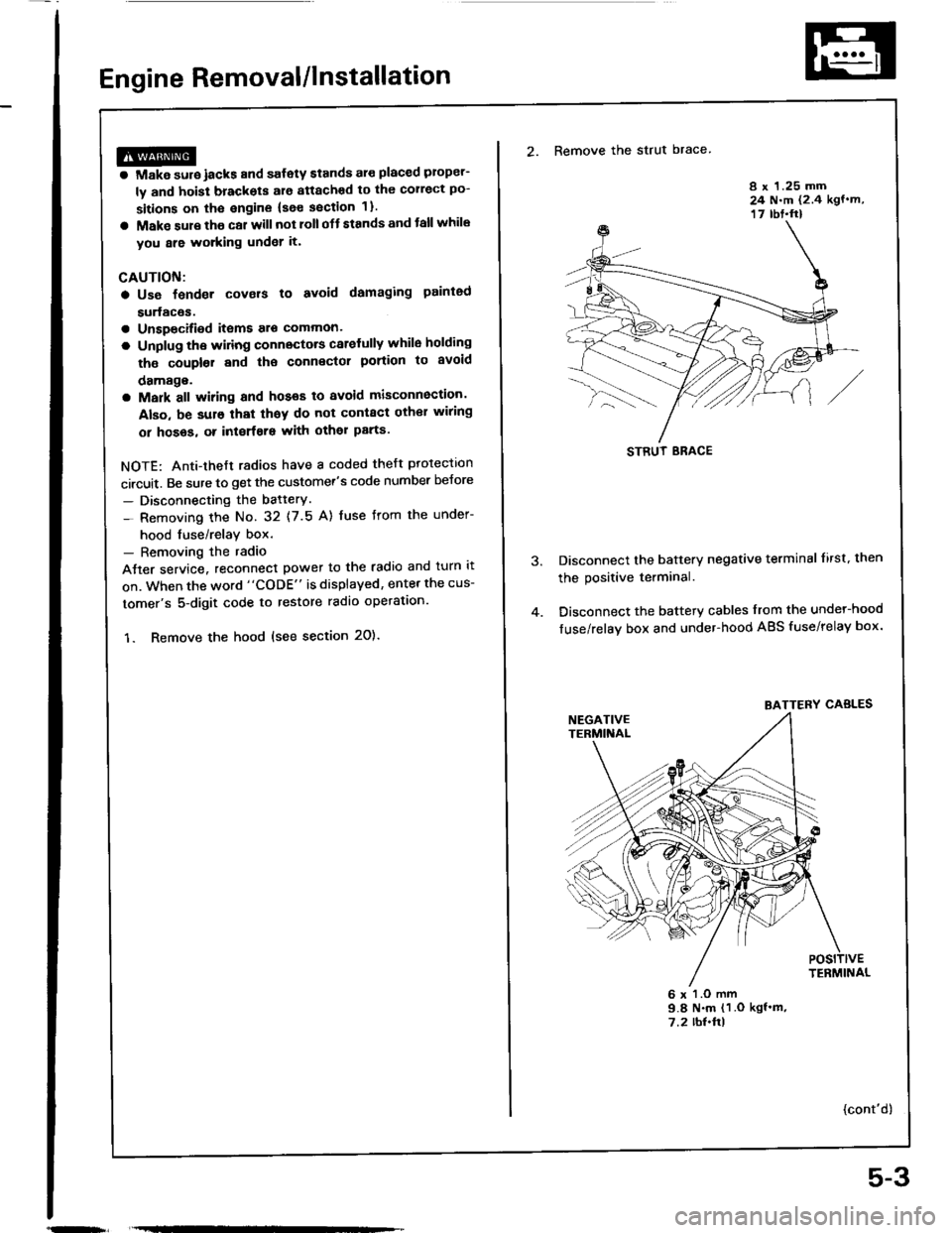
2. Remove the strut brace
8 x 1.25 mm24 N.m (2.4 kgf.m,17 rbt.ft)
Disconnect the battery negative terminal lirst. then
the positive terminal.
Disconnect the battery cables from the undel-hood
fuse/relay box and under-hood ABS fuse/relay box.
6 x l.O mm9.8 N.m (1 .O kgf'm,7.2 rbl.ftl
{cont'd)
STRUT ERACE
BATTERY CABLES
5-3
Page 60 of 1413
![HONDA INTEGRA 1994 4.G Workshop Manual Insrall the left front mount, then tighten the bolts in
the numbered sequence as shown (O-@),
O 12 x 1.25 ]n]n83 N.m 18.5 kst.m,61 lbt.ftlReplace.
@ 12 r 1.25 mm59 N.m {6.0 kgl.n,43 tb{.ftlReplace.
@ HONDA INTEGRA 1994 4.G Workshop Manual Insrall the left front mount, then tighten the bolts in
the numbered sequence as shown (O-@),
O 12 x 1.25 ]n]n83 N.m 18.5 kst.m,61 lbt.ftlReplace.
@ 12 r 1.25 mm59 N.m {6.0 kgl.n,43 tb{.ftlReplace.
@](/img/13/6067/w960_6067-59.png)
Insrall the left front mount, then tighten the bolts in
the numbered sequence as shown (O-@),
O 12 x 1.25 ]n]n83 N.m 18.5 kst.m,61 lbt.ftlReplace.
@ 12 r 1.25 mm59 N.m {6.0 kgl.n,43 tb{.ftlReplace.
@ 10 r 1.25 mm44 N.m (4.5 kgf.m, 33 lbt.ftl
k-
5-15
a Check that the sp.ing clip on the end of each
driveshaft clicks into place.
GAUTION: Uso oow spring clips.
a Bleed air trom the cooling system at the bleed bolt
with the heater valve open (see page 10-5).
a Adjust the th.ottle cable (see section 1 1).
a Check the clutch pedal tree play lsee section 12).
a Check that the transmission shifts into gear
smoothlv,
a Adiust the tension of the following drive belts.
Alternator belt {s€e section 23).
P/S pump belt {see section 17).
A/C comoressor belt (see section 22).
a Inspect tor fuel leakage (see section 1 1).
. After assembling fuel line parts, turn on the ig-
nition switch (do not operate th€ starter) so
that the Juel pump operates for approximat€-
lV two seconds and the tuel line pressurizes.
Repeat this operation two or three times and
check for fuel leakage at any point in the fuel
line.
(cont'd)
Page 68 of 1413
Valve Seals
Replacement (cylinder head removal not requiredl
NOTE: Cylinder head removal is not required in this
procedure.
The procodure shown below applies when using the in-
car valve spring compressor (Snap-on YA8845 with
Y AAA$-2A 718" attachment).
@@ whcn u3ing this tool, a: with any tool,
always u!€ agproved cyr Protcction. Using th.
right tool for cach iob hclps incraa3. produstivity
whilo 3ltrgu8rding tool!, cquipmcnt lnd the u3c1'
1. Turn the crankshaft so that the No. I and the No' 4
pistons are at top d€ad center (TDC).
2. Remove the cylinder head cover.
3. Remove the distributor.
4. Loosen and disconnect the timing belt from the
c8mshaft pulleys.
5. Remove the camshaft holde, bolts, then r€move the
camshaft holder, the camshaft and rocksr arms.
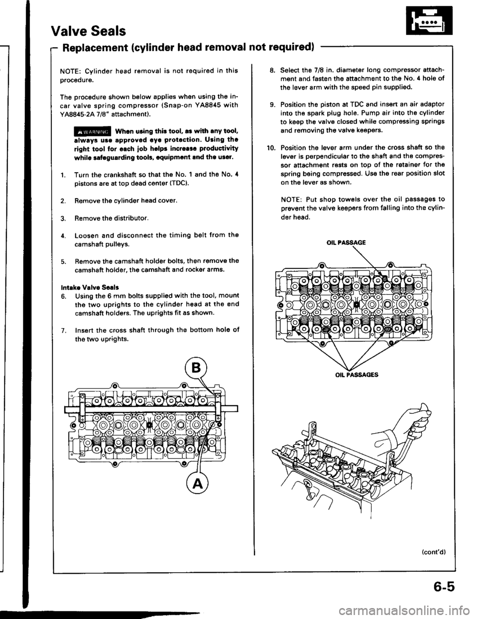
lntakc V!lv6 Sclls
6. Using the 6 mm bolts supplied with the tool, mount
the two up.ights to the cylinder head 8t the end
camshaft holde.s. The uprights fit as shown.
7. Insort the cross shaft through the bottom hole ot
the two up.ights.
6-5
OIL PASSAGE
OIL PASSAGES
Select the 7E in. diameter long compressor attach-
ment and fasten the attachment to the No. 4 hole of
the lever arm with the speed pin supplied.
Position the piston at TDC and insert an air adaptor
into th€ spark plug hole. Pump air into the cylinder
to keep the valv€ closed while cgmpressing springs
and removing the valve keepers.
Position the lever arm under the cross shaft so the
lever is psrpendicular to the shEft and ths compres-
sor attachment rests on toD of the rstainer for th€
spring being compressed. Use the rear position slot
on the lever as shown.
NOTE: Put shop towels over the oil passag€s to
prevent the valve keepers from falling into the cylin-
der h€ad.
(cont'd)
Page 72 of 1413
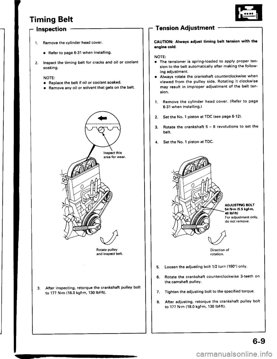
Timing Belt
Inspection
Remove the cylinder head cover.
. Reler to page 6-3'l when installing.
Inspect the timing belt for cracks and oil or coolant
soaking.
NOTE:
. Replace the belt if oil or coolant soaked.
. Rsmove any oil or solvent that gets on the belt.
Rotate pulley
and inspscr bell.
After inspecting, retorque the crankshaft pulley bolt
to 177 N'm ('18.0 kgf'm, 130 lbt'ft).
Tension Adjustment
CAUTION: Always Ediust timing belt tonsion with tho
cngin. cold.
NOTE:
. The tensionet is spring-loaded to apply proper ten-
sion to the belt automaticallv after making the follow-
ing adjustment.
. Always rotate the crankshaft counterclockwise when
viewed trom the pulley side Rotating it clockwise
may result in improper adjustment ot the belt ten-
sion.
Remove the cylinder head cover. (Refer to page
6-31 when installing.)
Set the No. 1 piston at TDC (see page 6-12).
Rotate the c.ankshaft 5 - 6 revolutions to set the
bslt.
4. Set the No. I piston at TDC.
3.
ADJUSNNG BOLT54 N.m (5.5 kqf.m,a0 rbr.ftlFor adiustment only,do not remove,
5.
6.
7.
8.
Direction olrolatlon.
Loosen the adiusting bolt 1/2 turn (180') onlv
Rotate the crankshaft counterclockwise 3-teeth on
the camshaft pulley.
Tighten the adjusting bolt to the specified torque.
After adjusting, retorque the crankshaft pulley bolt
to 177 N.m (18.0 kgl.m. 130 lbf.ft).
6-9
Page 83 of 1413
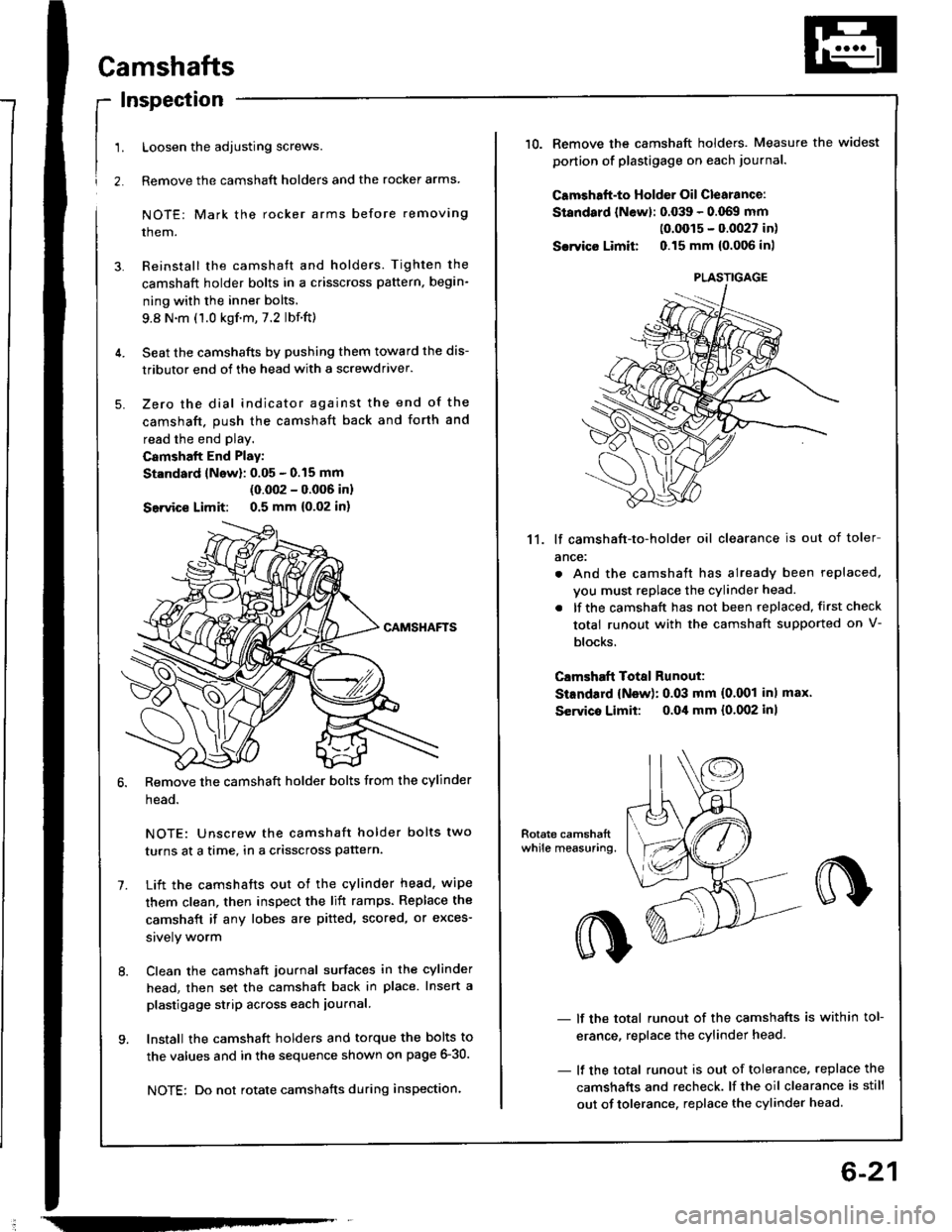
!
1.
2.
Camshafts
Inspection
Loosen the adjusting screws.
Remove the camshaft holders and the rocker arms
NOTE: Mark the rocker arms before removing
them.
Reinstall the camshaft and holders. Tighten the
camshaft holder bolts in a crisscross pattern, begin-
ning with the inner bolts.
9.8 N.m (1.0 kgf.m,7.2 lbf.ft)
Seat the camshafts by pushing them toward the dis-
tributor end of the head with a screwdriver.
Zero the dial indicator against the end of the
camshaft. push the camshaft back and forth and
read the end play.
Camshalt End Play:
St.ndard lNow): 0.05 - 0.15 mm
(0.002 - 0.006 inl
Seivice Limit: 0.5 mm {0,02 in)
Remove the camshaft holder bolts from the cylinder
head.
NOTE: Unscrew the camshaft holder bolts two
turns at a time, in a crisscross pattern.
Lift the camshafts out ot the cylinder head. wipe
them clean, then inspect the lift ramps. Replace the
camshaft if any lobes are pitted, scored, or exces-
srvely worm
Clean the camshaft journal surfaces in the cylinder
head, then set the camshaft back in place. Insert a
plastigage strip across each iournal.
Install the camshaft holders and torque the bolts to
the values and in the sequence shown on page 6-30.
NOTE: Do not rotate camshafts during inspection.
-
6-21
10.Remove the camshaft holders. Measure the widest
ponion of plastigage on each journa..
Camshaft-to Holder Oil Clearance:
Standard lNewl: 0.039 - 0.069 mm(0.0015 - 0.0027 in)
Sarvico Limit 0.15 mm {0.006 inl
11. lf camshaft-to-holder oil clearance is out of toler
ance:
. And the camshaft has already been replaced,
vou must replace the cylinder head.
. lf the camshaft has not been replaced, first check
total runout with the camshaft supported on V-
blocks.
Clmshaft Total Runout:
StEndard {New): 0.03 mm (0.001 inl max'
Servico Limit: o.Oil mm {0.002 inl
- lf the total runout of the camshafts is within tol-
erance, replace the cylinder head.
- lf the total runout is out of tolerance, replace the
camshafts and recheck. lf the oil clearance is still
out of tolerance. replace the cylinder head.
PLASTIGAGE
Page 91 of 1413
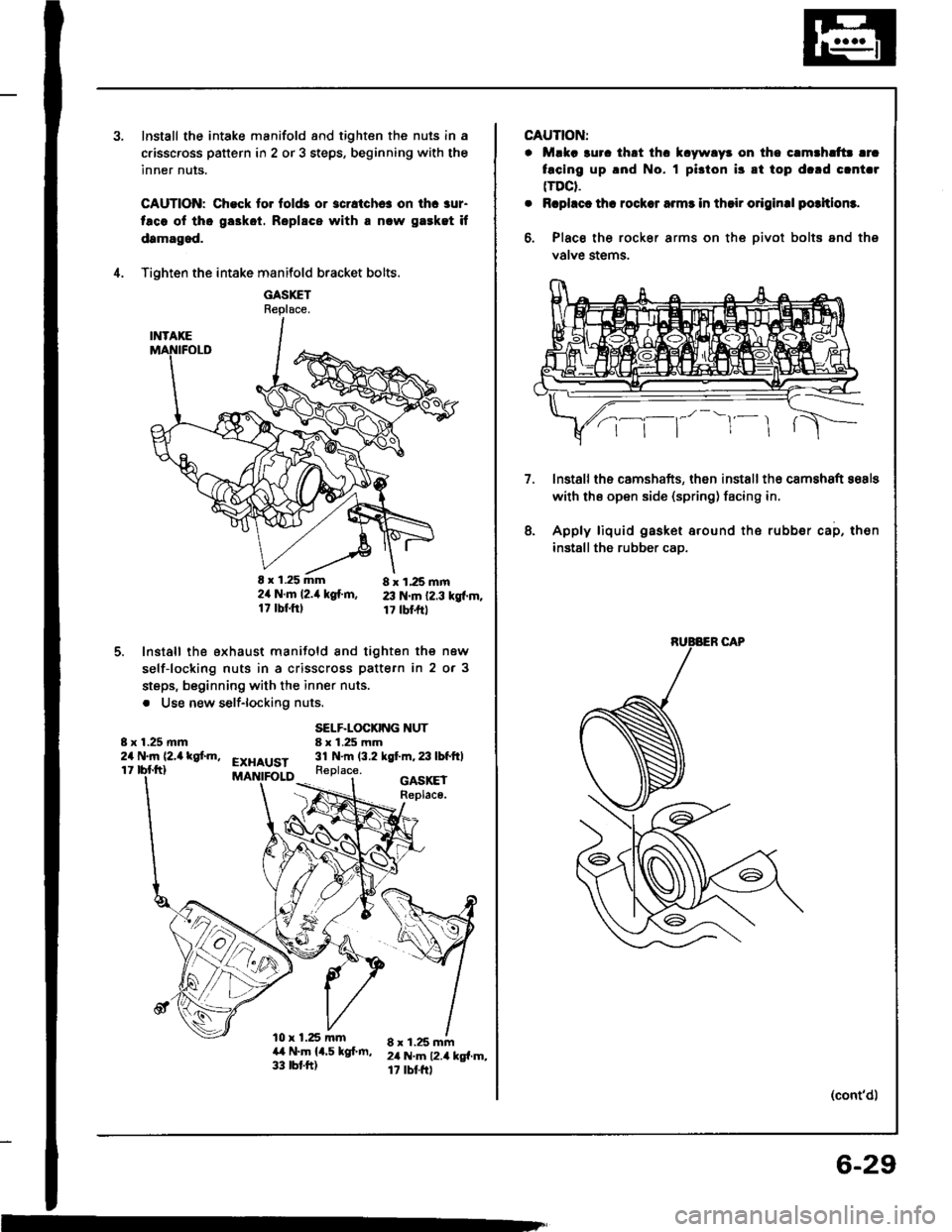
Install the intake manifold and tighten the nuls in a
c.isscross pattern in 2 or 3 steps, beginning with the
inner nuts.
CAUTION: Check to. fold3 or 3cratchc! on ihc aur-
taco ol tho ga3kot. Roplscs with a nlw gaeket if
damagod.
Tighten the intake manifold bracket bolts.
GASXETReplace.
E x 1.25 mm 8 x 1,25 mm2ir N.m l2.it kg{.m, 23 N.m 12.3 kgf.m.17 tbf.ftl 17 tbl.frt
Install the exhaust manifold and tighten the new
self-locking nuts in a crisscross pattern in 2 or 3
steps, beginning with the inner nuts.
. Use new self-lockiflg nuts.
4.
5.
8 x 1.25 mm24 N.m (2,a kgf.m,
SELF.LOCKING NUT8 x 1.25 mm31 N.m (3.2 kgt m,23lbfftlEXHAUST11Replace.
l0 x 1.25 mma,t N.m 14.5 kgf.m,33 tbt.ft)
GASKEIReplace.
8 x 1.25 mm2il N.m 12.4 kg{.m,17 rbtftl
m
CAUTION:
. Mlka 3uro thrt thc k.ywlyr on tho c.mthlttr lrc
facing up .nd No. I pi3ton i3 8t top d.rd clnt.r(TDCt.
. Rcphct th! rocksr armr in thsir o.iginal potltlom.
6, Place the rocker arms on the oivot bolts and ths
valve stems.
lnstallths camshafts, then installth€ camshaft sosls
with ths open side (spring) facing in.
Apply liquid gasket around the rubber cap, then
installthe rubber cao.
7.
8.
(cont'd)
6-29
Page 109 of 1413
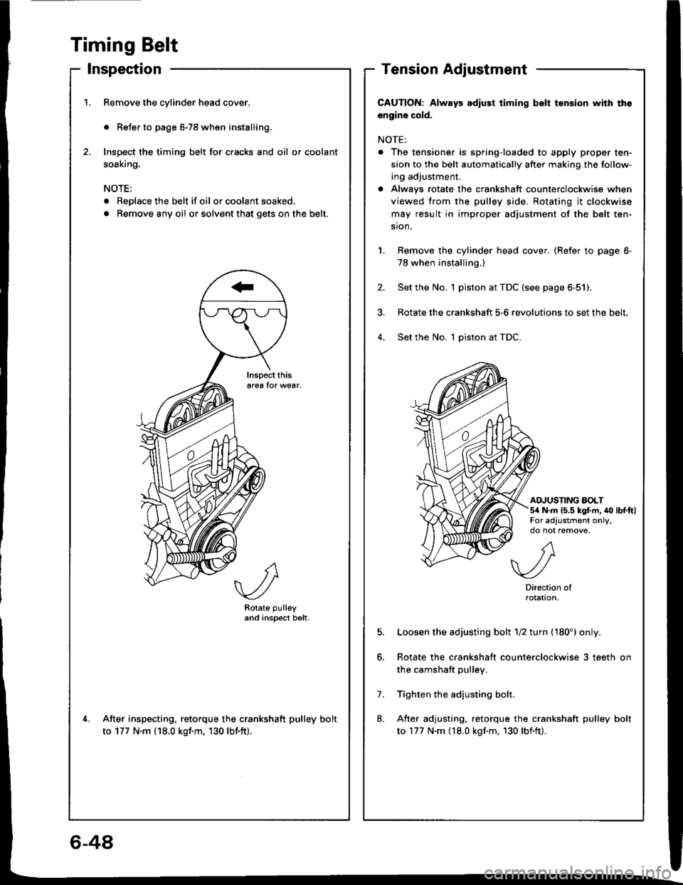
Timing Belt
lnspection
Remove the cylinder head cover.
. Refer to page 6-78 when installing.
Inspect the timing belt for cracks and oil or coolant
soaking.
NOTE:
. Replace the belt if oil or coolant soaked.
. Remove any oil or solvent that gets onthe b€lt.
Rotate pulleyand inspect b6lt.
After inspecting. retorque the crankshaft pulley bolt
to 177 N.m (18.0 kgf.m, 130 lbf.ft).
Tension Adjustment
CAUTION: Always adlust timing bslt tsnsion with th6
engine cold.
NOTE:
. The tensioner is spring-loaded to apply proper ten-
sion to the belt automatically after making the follow-
ing adjustment.
a Alwavs rotate the crankshaft counterclockwise when
viewed trom the pulley side. Rotating it clockwise
may result in improper adjustment of the belt ten-
sion.
Remove the cylinder head cover. (Refer to page 6-
78 when installing.)
Set the No. 1 piston at TDC (see page 6-51).
Rotate the crankshaft 5-6 revolutions to set the belt.
Set the No. 1 piston at TDC.4.
AINUSTING AOLT5/a N.m 15.5 kg{.m, to lbtftlFor adjustment only,
5.
7.
8.
A
.//\v-/
Directionrotat|on,
Loosen the adjusting bolt 1/2 turn (180') only.
Rotate the crankshaft counterclockwise 3 teeth on
the camshaft pulley.
Tighten the adjusting bolr.
After adjusting, retorque the crankshaft pulley bolt
to 177 N.m (18.0 kgf.m, 130 lbf'ft).
6-48