cks HONDA INTEGRA 1994 4.G Owner's Manual
[x] Cancel search | Manufacturer: HONDA, Model Year: 1994, Model line: INTEGRA, Model: HONDA INTEGRA 1994 4.GPages: 1413, PDF Size: 37.94 MB
Page 323 of 1413
Emission Control System
Positive Crankcase Ventilation (PCVI System
Description
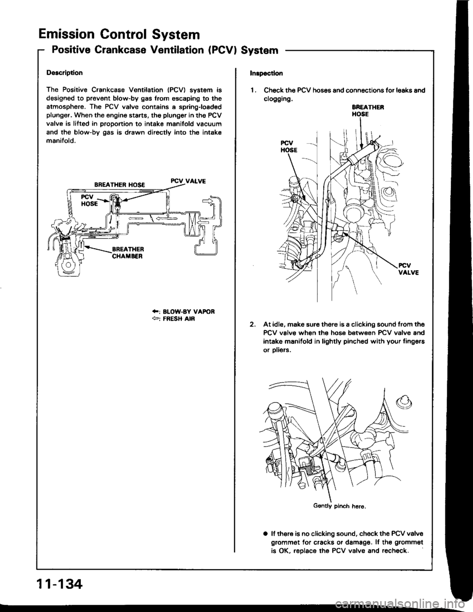
The Positive Crankcase Ventilation (PCV) system is
designed to prevent blow-by gas {rom escaping to the
atmosphsre. The PCV valve contains a spring-loadsd
plunger. When the Bngine starts, the plunger in the PCV
valve is lifted in proportion to intake manifold vacuum
and the blow-by gas is drawn directly into th€ intak€
manifold.
FCV VALVE
.F: ILOW-BY VAFORer FRESH AIR
11-134
Insp€cdon
1. Check th€ PCV hos6s and connections tor lsaks and
clogging.
At idle, mak6 sur€ th6fe is a clicking sound from th6
PCV valve when the hose between rcV valve and
intake manifold in lightly pinched with your fingors
or oli€rs.
a lf thera is no clicking sound, ch6ck the PCV valve
grommet for cracks or damage. ll the grommet
is OK, reolace the PCV valve and recheck.
2.
SREATHER
Gontly pinch hero.
Page 334 of 1413
Adjustment
NOTE:
a To check the clutch interlock switch and clutch
switch, see seclion 23.
a The clutch is selt-adjusting to compensate for wear.
CAUTION: It there is no clearanco between the mastel
cylinder piston and push lod. the releaso boaring is held
againsl the diaphragm spring, which can result in clutch
slippage 01 othel clutch problems.
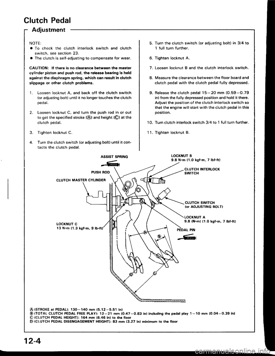
Loosen locknut A, and back otf the clutch switch
{or adjusting bolt) until it no longer touches the clutch
pedal.
Loosen locknut C, and turn the push rod in or out
to get the specified stroke (@) and height (O) at the
clutch pedal.
Tighten locknut C.
Turn the clutch switch (or adjusting bolt) until it con-
tacts the clutch pedal.
Turn the clutch switch (or adjusting bolt) in 3/4 to
1 full turn further.
Tighten locknur A.
7. Loosen locknut B and the clutch interlock switch.
8. Measure the clearance between the tloor board and
clutch pedal with the clutch pedal tully depressed.
9. Release the clutch pedal 15-20 mm {O.59-O.79
in) from the fully depressed position and hold it there.
Adiust the position of the clutch interlock switch so
that the engine will start with the clutch pedal in this
oosition.
1 0. Turn clutch interlock switch 3/4 to 1 tull turn funher.
11. Tighten locknut B.
LOCKNUT B9.8 N.m (1.0 kgf.m, 7 lbf.ftl
CLUTCH INTERLOCKswtrcH
6.
1.
2.
ASSIST SPRING
-6ll
LOCKNUT Cl3 N.m l'l.3 kgf.m, 9
CLUTCH SWITCH{or AOJUSTING BOLTI
LOCKNUT A9.8 {N.ml (1.0 kgl.m, 7 lbt.ftl
(STROKE at PEDALI: 130-140 mm 15.12-5.51 in){TOTAL CLUTCH PEDAL FREE PLAY): 12-21 mm 10.47-0.83 inl including tho p.dal play I -lO mm 10.04-0.39 inl{CLUTCH PEDAL HEIGHTI: 164 mm (6.46 in} to tho lloot{CLUTCH PEDAL DISENGAGEMENT HEIGHTI: 83 mm 13.27 inl minimum to tho lloo.
PUSH ROD
CLUTCH MASTER CYLINDER
Clutch Pedalctutch Pedat I
[-],ll'"-"" f
| :;i:'":fff*tr#:?iff:".,*::,::". | .#::J:::
sb''�'�'""
| |
| "orr,O", It there is no clearanco between the master | ,. aoo""n locknut B and the clutch intertoct switcl. | |cylinder piston and push lod. the releaso boaring is held | | Iagainst the diaphragm spring, which can result in clutch | 8. Measure tne clearance between the floor board and I Islippage 01 othel clutch problems.
I
clutch pedal with the clutch pedal tully deeressed.
I I1. Loosen locknut A, and back otf the clutch switch | 9. Release the clutch pedal 15-2O mm (O.59-O.79 I I
{or adiusting boltl until it no longer touches the clutch I int trom ttre fully depressed position and hold it there. I I
, ::":"" rocknut c, and rurn the push rod in or out | iliiiliffi:l1l:J"'1"-:H"l:tJ:i"i#fT: I I
. il*:*j':"'-(@)andheisht(olatthe
|
,:.;:,nterrockswitch3/4torrurrturnturtner.
I tf
,
::
***r**''
.,".,u"**;
|
'-"'"'';*1,,0*.,.-,.,*,
I I
Page 337 of 1413
Pressure Plate
RING GEAR HOLDER07LAB-PVOOl OO or07924-PD20003
Removal/lnspection
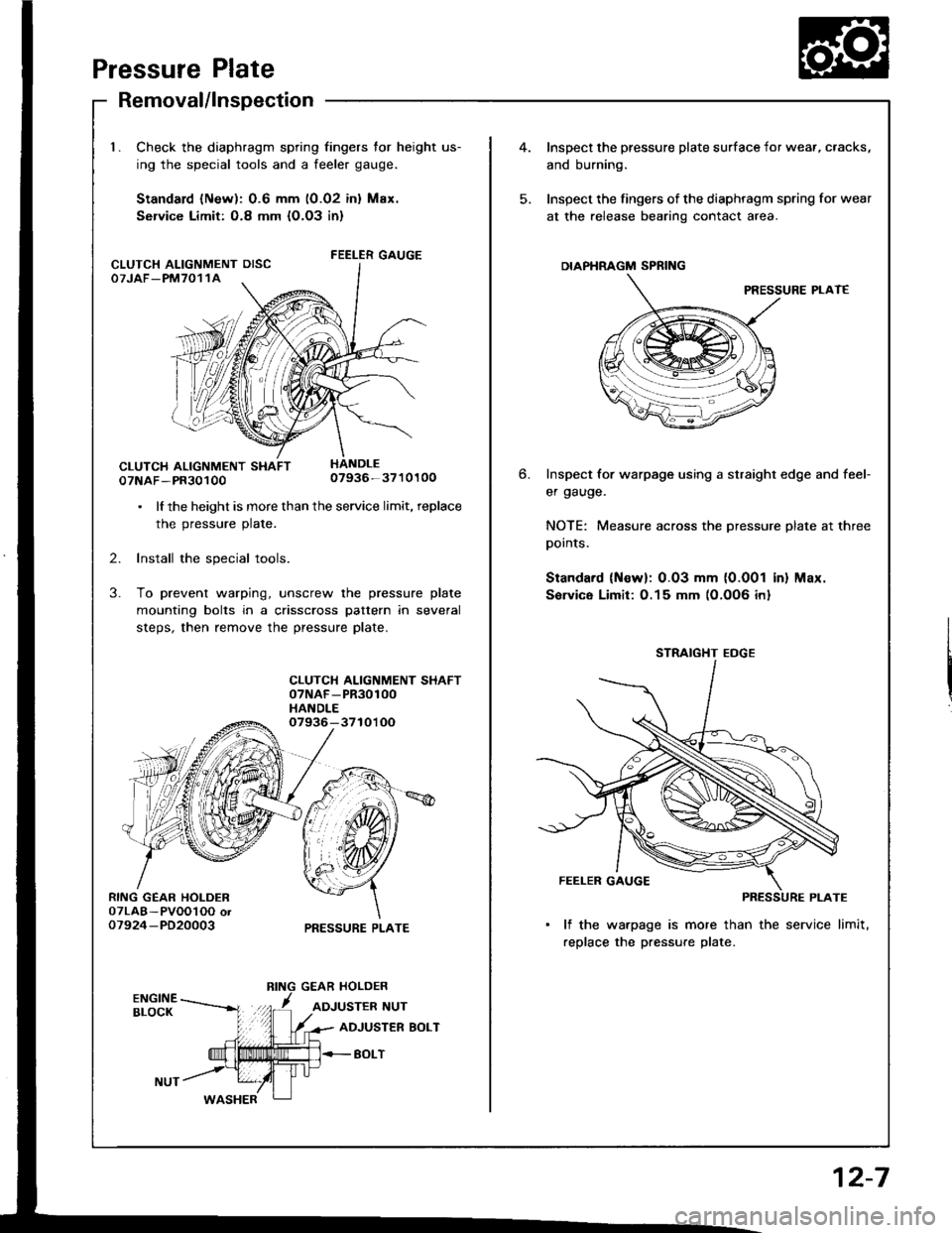
Check the diaphragm spring fingers for height us-
ing the special tools and a feeler gauge.
Standard lNew): 0.6 mm (0.02 inl Max.
Service Limit: O.8 mm {O.O3 in}
FEELER GAUGE
07NAF-PR3010007936-3710100
. lf the height is more than the service limit, replace
the pressure plate.
2. Install the special tools.
3. To prevent warping, unscrew the pressure plate
mounting bolts in a crisscross pattern in several
steps, then remove the pressure plate.
CLUTCH ALIGNMENT SHAFT07NAF-PR30100HANDLE07936-3710'l OO
PRESSURE PLATE
CLUTCH ALIGNMENT OISCOTJAF_PM7011A
4.Inspect the pressure plate surface
and burning.
Inspect the fingers of the diaphrag
at the release bearing contact ar
DIAPHRAGM SPRING
Inspect for warpage using a stru
er gauge.
NOTE: Measure across the prer
pornls.
Standard (Newl: 0.03 mm (0.0
Sorvice Limit:0.15 mm (0.0O6
STRAIGHT EOGE
FEELER GAUGE
PI
lf the warpage is more than
replace the pressure plate.
6.
I surface for wear, cracks,
diaphragm spring for wear
nracr area.
PRESSURE PLAT€
straight edge and feef
pressure plate at three
0.001 in) Max.
)O6 inl
12-7
Page 339 of 1413
InspectionReplacement
Flywheel, Flywheel Bearing
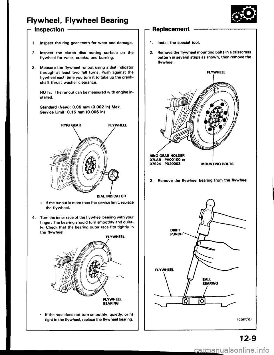
Inspect the ring gear teeth for wear and damage.
Inspect the clutch disc mating surface on the
flywheel fo. wear, cracks, and burning.
Measure the flywheel runout using a dial indicator
through at least two full tu.ns. Push against the
Ilywheel each time you turn it to take up the crank-
shaft thrust washe. clearance.
NOTE; The runout can be measu.ed with engine in-
stalled.
Standard (ttlervl: O.O5 mm (O.002 inl Max.
Service Limit: 0.15 mm 10.006 inl
RING GEABFLYWHEEL
DIAL II{DICATOR
It the runout is more than the service limit, leplace
the flvwheel.
Turn the inner race of the flywheel bearing with your
finger. The bearing should turn smoothly and quiet-
ly, Check that the bearing outer race fits tightly in
the flvwheel.
FLYWHEELBEARING
It the race does not turn smoothly, quietly, or fit
tight in the flywheel, replace the flywheel bearing.
Install the special tool.
Remov€ the flywhe€l mounting bolts in a criascross
pattern in several steps 8s shown, then remove the
tlywheel.
MOUI{TII{G BOLTS
3. Remov€ the flywheel bsaring from th€ tlywheel.
(cont'd)
FLYWHEEL
12-9
Page 351 of 1413
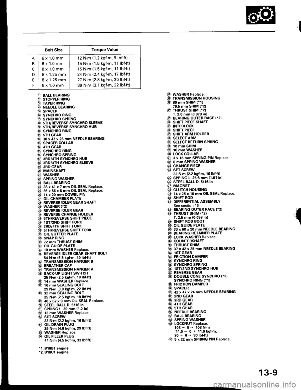
12 N.m (1.2 kgim,9 lbnft)
15 N.m (1.5 kgnm, 11 lbf.ft)
15 N.m (1.5 kgf.m, 11 lbf.ft)
24 N.m (2.4 kgf.m, 17 lbf'ft)
27 N.m (2.8 kgnm,20 lbnft)
30 N.m (3.1 kgf.m, 22 lbf'ft)
Bolt Size
,l
{
@@69
@
@@@@@@@@6Dq0
o€xv0@
@0!@@@@al
61@
B
c
D
E
F
6x1.0mm
6x1.0mm
I x 1.0 mm
8 x 1.25 mm
8 x 1.25 mm
8 x 1.0 mm
i) BALL BEARINGe sroPPER R|NG9 TAPER RINGA NEEDLE EEARINGO SPACER.d SYNCHRO RINGt sYNcHRo SPR|NG!) 5TH/REVEFSE sYNcHRo SLEEVEO 5TH/REVERSE SYNCHRO HUB[0 sYrucxao nlrucii i) 5TH GEARO 38 x 43 x 26 mm NEEDLE BEARINGt3 SPACEE COLLARO 4TH GEAR.iB SYNCHRO FING.Ii9 SYNCHRO SPRING{, 3RD/,ITH SYNCHRO HUB
@ 3RD/4TH SYNCHBO SLEEVEt9 3RD GEARO MAINSHAFTO wasHER@) SPRING WASHER40 BALL BEARINGO 28 x 41 x ? mm OIL SEAL Replace.ad 35 x 56 x 8 mm OIL SEAL Replace.a0 14 x 20 mm OOWEL PIN@ OIL CHAMBER PLATE'A BEVERSE IDLEN GEAR SHAFT@ wasHER t-2).A REVERSE IDLER GEAFO REVERSE CHANGE HOLDER3A sTH/REVERSE SHIFT PIECEO 1ST/2ND SHIFT FORK04 3RD/.TH sHlFr FoRK@ 5TH/REVERSE SHIFT FORKO9' OIL GUTTER PLATE6' SNAP RING@ 72 mm THRUST SHIM) OIL GUIOE PLATEi!0 10 mm WASHER Replace..4i] REVERSE IDLER GEAR SHAFT BOLT54 N.m {5.5 kgt m, 40lblftl) TRANSMISSION HANGER B(3 BREATHER CAP@ TRANSMISSION HANGER A63 BACK.UP LIGHT SWITCH25 N.m (2.5 ksf.m, 18lbfftl@r 14 mrn waSHER Replace.67 16 mm SEALING BOLT29 N.m (3.0 kgl.m, 22 lbf ft)@ 32 mm SEALING BOLT25 N.m (2.5 kgf.m. 18lbt'ft|@ 40 x 62 x 9 mm OIL SEAL Replace.D STEEL BALL D. 5/16 inGl SPRING L. 30 mm {1.2 in}
@ 12 mm WASHER Replace.63) SET SCREW22 N.m 12.2 kgl.m, 16 lbt'ft,@ OIL ORAIN PLUG39 N.m {4.0 kgt.m, 29 lbf'ftl€9 WASHER Replace.@ oIL FILLER PLUG4,1N.m 14.5 kgJ m, 33 lblftl
*1:81881 engine*2:B18Cl engine
WASHER Beplace.TRANSMISSION HOUSING80 mm SHIM (*1)79.5 mm SHIM {*21THRUST SHIM {*2IT. 2.0 mm (0.079 in)BEARING OUTER RACE {*2}SHIFT PIECE SHAFTINTERLOCKSHIFT PIECESHIFT ARM HOLDERSELECT ARMSELECT RETURN SPRING10 mm SHIM10 mm WASHERLOCK COLLAR3 x 16 mm SPRING PIN Replace.8 mm SPRING WASHERCHANGE PIECESET SCREW22 N.m {2.2 kgf.m, 16 lbf.ft}SPRING L.25.6 mm {1.01 inlSTEEL BALL D. 5/16 inMAGNETCLUTCH HOUSING14 x 25 x 16 mm OIL SEAL Replace.SHIFT RODDIFFERENTIAL ASSEMBLYSee section 15BEARING OUTER RACE I*2ITHRUST SHIM I*2)T. 2.5 mm (0.098 in,SHIFT ROD BOOTOIL GUID€ PLATE33 x 60 x 20 mm NEEDLE BEARINGBEARING RETAINER PLATELOCK WASHER Replace.COUNTERSHAFTTHRUST SHIM37 x 42 x 25 mm NEEDLE BEARINGlST GEARFRICTION DAMPERSYNCHRO RINGSYNCHRO SPRINGlST/2ND SYNCHRO HUBREVERSE GEARDOUBLE CONE SYNCHRO I*2ISYNCHRO BING I*1)FRICTION DAMPERSPACER42 x 6? x 24 mm NEEDLE BEARING2ND GEAR3RD GEAR4TH GEAS5TH GEARNEEDLE BEARINGBALL BEARINGSPRING WASHERLOCKNUT Replace.108 - 0- 108 N.m(11.0 - 0* 11.0 kgt m,80- 0- 80lbf.ft)5 x 22 mm SPRING PIN Replace.00
13-9
Page 367 of 1413
- Disassembly
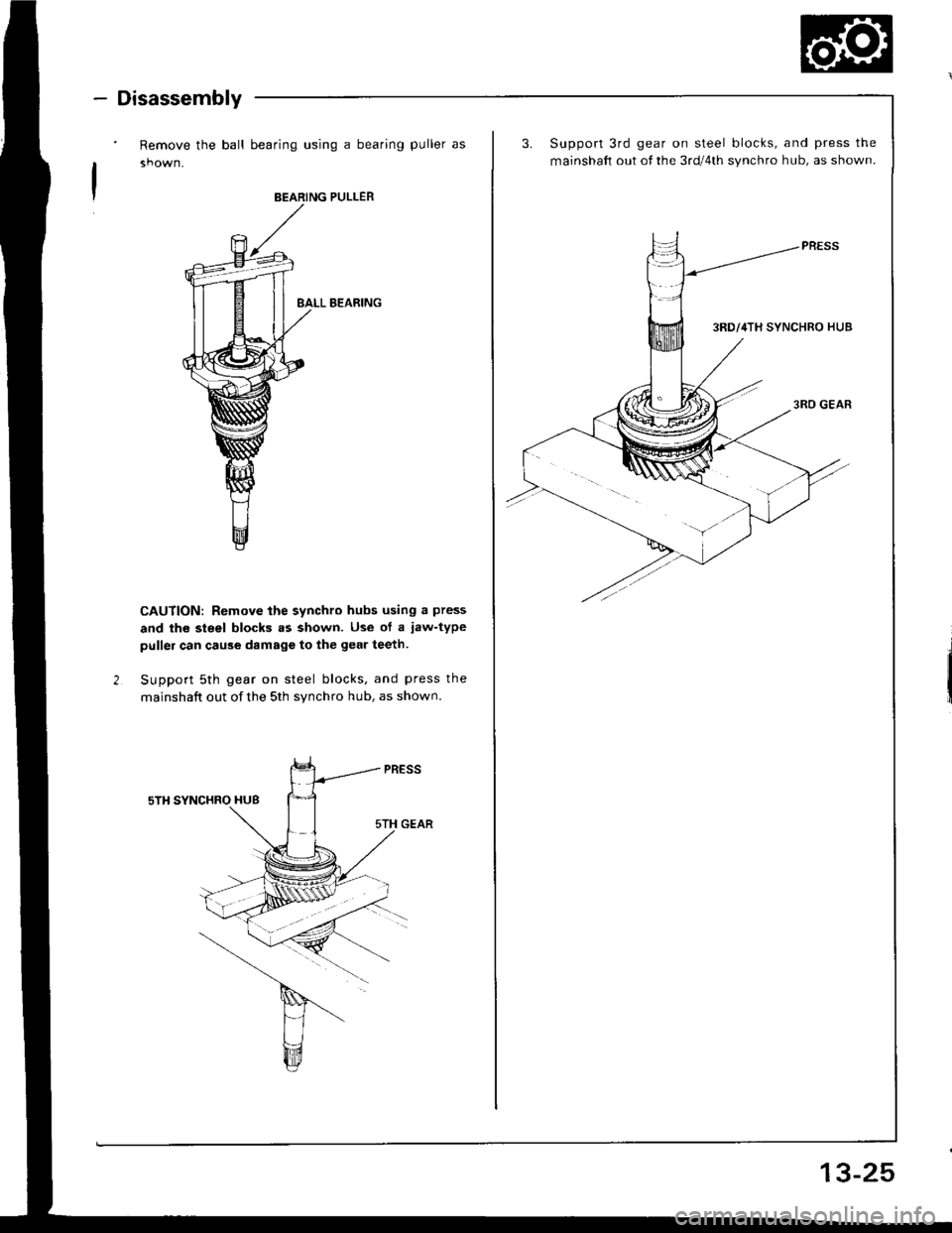
Remove the ball bearing using a bearing puller as
BEARING PULLER
BALL B€ARING
CAUTION: Remove the synchro hubs using a press
and the steel blocks .s shown. Use of a jaw-type
puller can cau3e damags to the gear teeth.
Support 5th gear on steel blocks, and press the
mainshaft out of the 5th synchro hub, as shown.
3.Support 3rd gear on steel blocks, and press the
mainshaft out of the 3rd/4th synchro hub, as shown.
13-25
Page 369 of 1413
1_
ReassemblV
ATTACHMENT,35 mm LD.07746 - 0o30/rc0
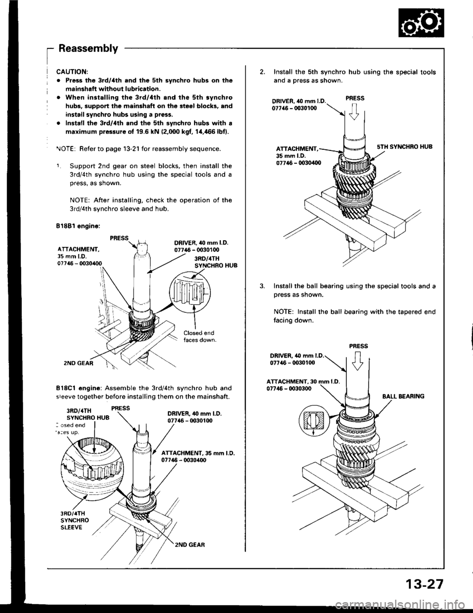
CAUTION:
o Pless the 3rd/ilth and the 5th synchro hubs on the
msinshafi without lubrication.
. When installing the 3rd/4th and the sth synchro
hubs, support the mainshaft on the steel blocks, and
install synchro hubs using a press,
. Install the 3rd/,lth and the sth synchro hubs with a
maximum pressure of 19.6 kN (2.000 kgf, 1+466lbt).
^JOTEi Refer to page 13-21 for reassembly sequence.
Support 2nd gear on steel blocks, then install the
3rd/4th synchro hub using the special tools and a
press, as shown.
NOTE: After installing, check the operation of the
3rd/4th synchro sleeve and hub.
B18Bl sngine:
DRIVER. 40 mm l.D.07746 - 0030100
3RD/4THSYNCHRO HUB
2NO GEAR
8l8Cl engine: Assemble the 3rd/4th synchro hub and
sreeve together before installing them on the mainshaft.
3RO/4TH PRESS
SYNCHRO HU8DRIVER- 4o mm l.D.07746 - tD30100: osed end
3RD/TTHSYNCHROSLEEVE
2, Install the sth synchro
ano a press as snown.
OBIVER, ,O mm LD.0t7it6 - 003010O
ATTACHMENT,35 mm l.D.
hub using the special tools
PRESS
sTH SYNCHRO HUB
077t6 - 00304{x)
Install the ball bearing using the special tools and a
prsss as shown.
NOTE: Install the ball bearing with the tapered end
facing down.
2ND GEAR
13-27
Page 372 of 1413

Countershaft Assembly
Disassembly
13-30
't.Securely clamp the countershaft assembly in a
bench vise with wood blocks.
Raise the locknut tab from the groove in the coun-
tershaft, then remove the locknut and the spring
washer.
4,Remove the bearing outer .ace, then remove the
needle bearing using a bearing puller as shown.
2.
BEARING PULLER
BEARING
Remove the ball bearing using a bearing puller as
shown.
CAUTION: Romove the gclrs using a pross and tho
steol blocks rs shown. U3a of a l.w.typo pullor can
cau36 damagg to tho gsar iocth.
Support 4th gear on steel blocks. and press the
countershaft out of sth and 4th gears, as shown.
PULlTR
\-Y
Page 375 of 1413
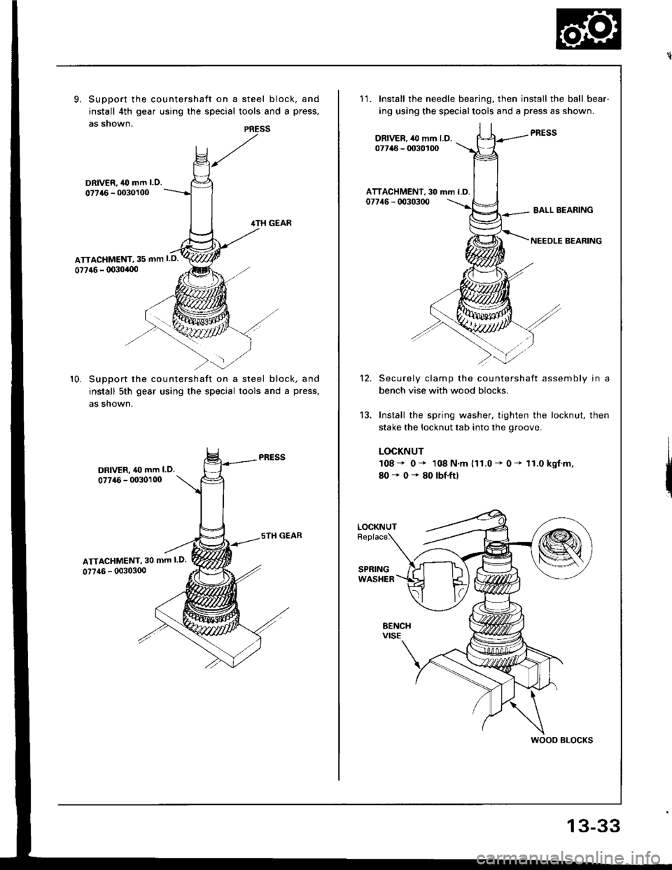
9. Support the countershaft on a steel block, and
install 4th gear using the special tools and a press,
as snown.PRESS
DRIVER, 40 mm l.O.
077{6 - 0030100
10. SuDDort the countershaft on a steel block, and
install 5th gear using the special tools and a press,
as shown.
DRIVER, 40 mm l.O.07746 - 0030100
ATTACHMENT, 30 mm l.O.
0?7a6 - (X)303(x)
11.Install the needle bearing. then install the ball bear-
ing using the specialtools and a press as shown.
PRESSDRIVER.,l0 mm l.D.07746 - 0030100
ATTACHMENT, 30 mm l.D.07746 - d)30300BALL BEARING
NEEDLE BEARING
12.
13.
Securely clamp the countershaft assembly in a
bench vise with wood blocks.
Install the spring washer. tighten the locknut, then
stake the locknut tab into the groove.
LOCKNUT
108* 0* 108 N.m (11.0 - 0 - 11.0 kgf.m,
80+0*80lbf.ftl
LOCKNUT
wooo BLocKs
13-33
Page 377 of 1413
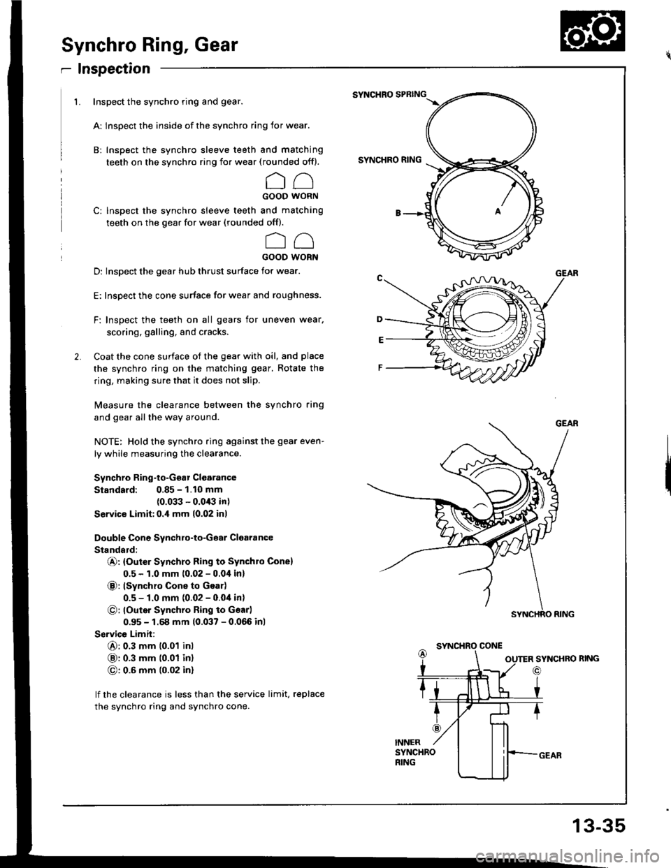
Synchro Ring, Gear
r Inspection
1. Inspect the synchro ring and gear.
A: lnspect the inside of the synchro ring for wear.
B: Inspect the synchro sleeve teeth and matching
teeth on the synchro ring for wear (rounded off).
CCGOOD WORN
C: Inspect the synchro sleeve teeth and matching
teeth on the gear for wear (rounded offl.
oo
GOOD WORN
D: Inspect the gear hub thrust surface for wear.
E: Inspect the cone surface for wear and roughness.
F: Inspect the teeth on all gears for uneven wear.
scoring, galling, and cracks.
Coat the cone surface of the gear with oil, and place
the synchro ring on the matching gear, Rotate the
ring, making sure that it does not slip.
Measure the clearance between the synchro ring
and gear allthe way around.
NOTE: Hold the synchro ring against the gear even-
ly while measuring the clearance.
Synchro Ring-to-Ggar Clgarance
Standard: 0.85 - 1.10 mm(0.033 - 0.0/B in)
Service Limit:0.i1 mm 10.02 inl
Double Cone Synchro-to-Gear Cloaiance
Standald:
@: {Outer Synchro Ring to Synchro Cone)
0.5 - 1.0 mm 10.02 - 0.0i1in)
@: lSynchro Cone to Goar)
0.5 - 1.0 mm (0.02 - 0.04 in)
O: loutsr Synchro Ring to Gsarl
0.95 - 1.68 mm (0.037 - 0.066 inl
Service Limit:
6): 0.3 mm 10.01 inl
@: 0.3 mm t0.01 inl
G): 0.6 mm (0.02 in)
lf the clearance is less than the service limit, replace
the synchro ring and synchro cone.
SYNCHRO SPBING
SYNCHRO RING
SYNCHRO CONE
SYNCHRO RING
o
13-35