cks HONDA INTEGRA 1994 4.G User Guide
[x] Cancel search | Manufacturer: HONDA, Model Year: 1994, Model line: INTEGRA, Model: HONDA INTEGRA 1994 4.GPages: 1413, PDF Size: 37.94 MB
Page 127 of 1413
Gamshafts
Inspection (cont'd)
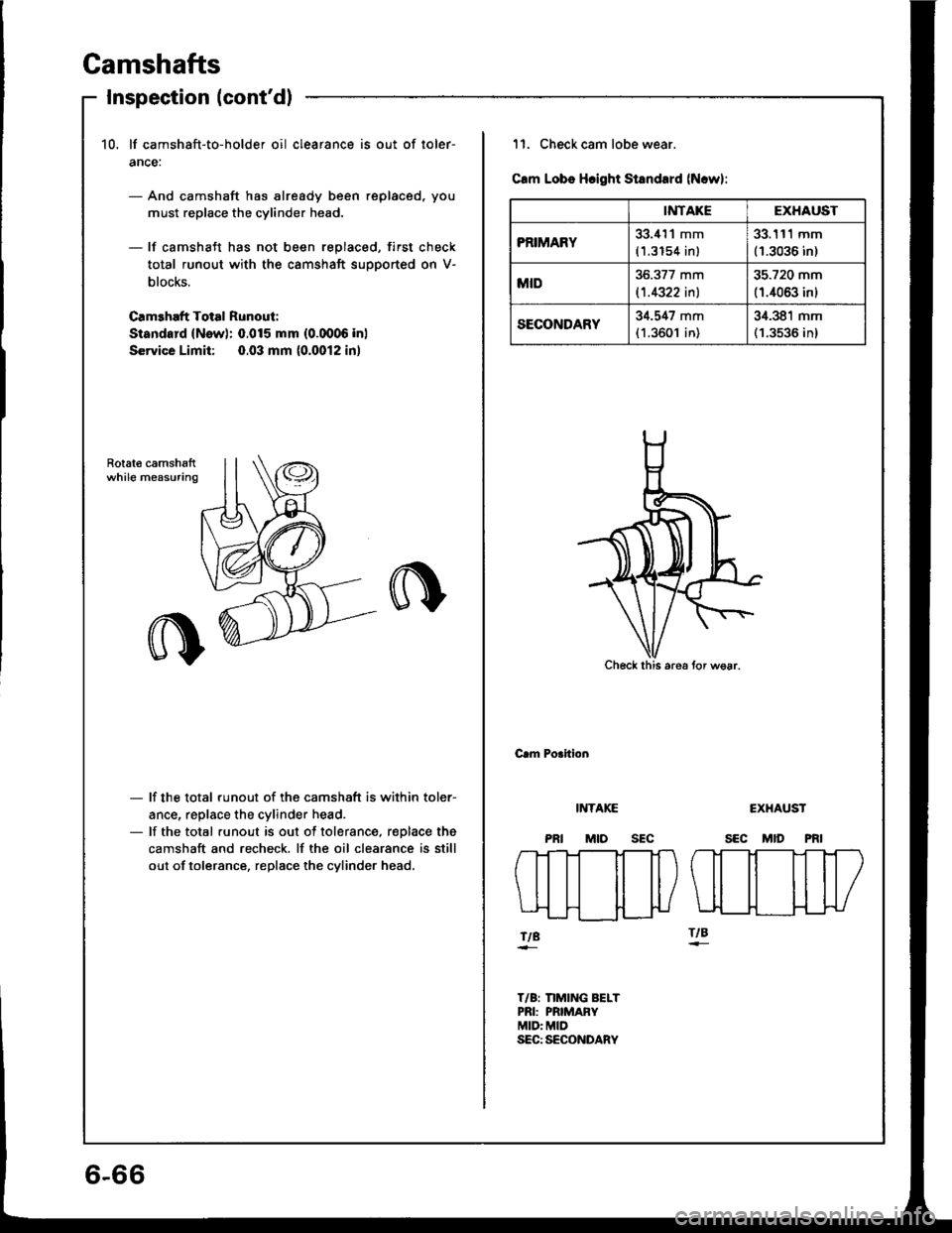
10, lf camshaft-to-holder oil clearance is out of loler-
ance:
- And camshaft has already been replaced, you
must replace the cylinder head.
- lf camshaft has not been replaced, first check
total runout with the camshaft supported on V-
blocks.
Camehaft Total Runout:
Sisndard (New): 0.015 mm (0.0006 inl
Service Limit: 0.03 mm (0.0012 in)
Rotat€ camshsftwhile measuring
- lf the total runout of the camshaft is within toler-
ance, replace the cylinder head.- lf the total runout is out of tolerance, r€Dlace the
camshaft and recheck. lf the oil clearance is still
out of tolerance. replace the cylinder head.
6-66
IiITAKEEXHAUST
PRIMARY33.i{'l1 mm
(1.3154 inl
33.111 mm(1.3036 in)
MID36.377 mm
l't.4322 inl
35.720 mm
(1.4063 inl
SECONDARY34.547 mm(1.3601 in)
34.381 mm(1.3536 in)
11. Check cam lobe wear.
Clm Lobs Hcight Standard (N.w):
Check this are6 tor wsar.
Crm Porition
INTAKE
MtosEc
CXHAUST
SEC MID PRI
fTt-]--Tt-Tt-l
\ll il il|/
tt ttlLIL__H___}{-}U
ftBftB
T/B: nMING BELTPRI: PRIMAFYMID: MIDSEC: SECONDARY
Page 143 of 1413
lllustrated Index
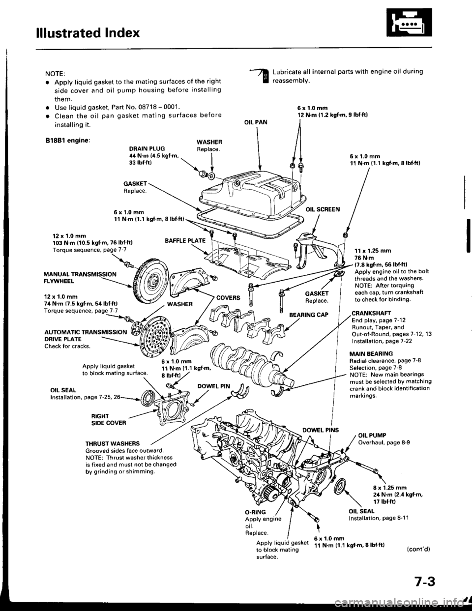
NOTE:
. Apply liquid gasket to the mating surfaces of the right
side cover and oil pump housing before installing
them.
. Use liquid gasket, Pan No.08718 - 0001.
. Clean the oil pan gasket mating surfaces before
installing it.
Bl8Bl engine: wAsHEF
Lubricate all internal parts with engine oil during
reassemory.
6x1.0mm12 N.m (1.2 kgf.m,I lbf.ftl
6x1.0mm11 N.m (1.1 kgf.m,8lbtft)
OIL SCREEN
11 x 1.25 mm76 N.m17.8 kgl.m, 56 lbf ftlApply engine oilto the bolt
threads and the washers.NOTE: After torquingeach cap, turn crankshaftto check lor binding.
DRAIN PLUG44 N.m {4.5 kgf.m,33 tbtfr)
GASKETReplace.
6x1.0mm1'l N.m {1.1 kgt.m, I lbtft)
OIL PAN
O.RING
GASKETReplace.
BEARING CAP
12 x 1.0 mm103 N.m (10.5 kgf.m, ?6lbf ft)
MANUALFLYWHEEL
'12 x 1.0 mm74 N.m {7.5 kgt m,54lbf.ftlTorque sequence, page 7 7
DRIVE PLATECheck for cracks,
AUTOMATIC TRANSMISSION
WASHER
6x1.0mm11 N.m {1.1 kgl.m,8 tbf.frt
CRANKSHAFTEnd play, page 7-12Runout, Taper, andOut-of-Round, pages 7 12, 13Instsllation, page 7 22
MAIN BEARINGRadial clearance, page 7-8
Sel€ction, page 7-8NOTE: New main bearingsmust be selected by matching
crank and block identificationmarkrngs.
Apply liquid gasket
to block mating surface.
OIL SEALInstallation, page 7-25,
RIGHTSIDE COVERDOWEL PINSOIL PUMPOverhaul, page 8-9THRUST WASHERSGrooved sides face outward.NOTE: Thrust washer thicknessis tixed and must not be changedby grinding or shamming.
8 x 1 .25 mm2,1 N.m {2.4 kgt m,17 tbt.ft)
OIL SEALInstallation, page 8-11Apply engrneorl.Replace.
Apply liquid gasket
to block mating
6x1.0mm'11 N.m {1.1 kgf'm, 8 lbl ft)(conr'dl
7-3
Page 155 of 1413
Pistons
Inspection
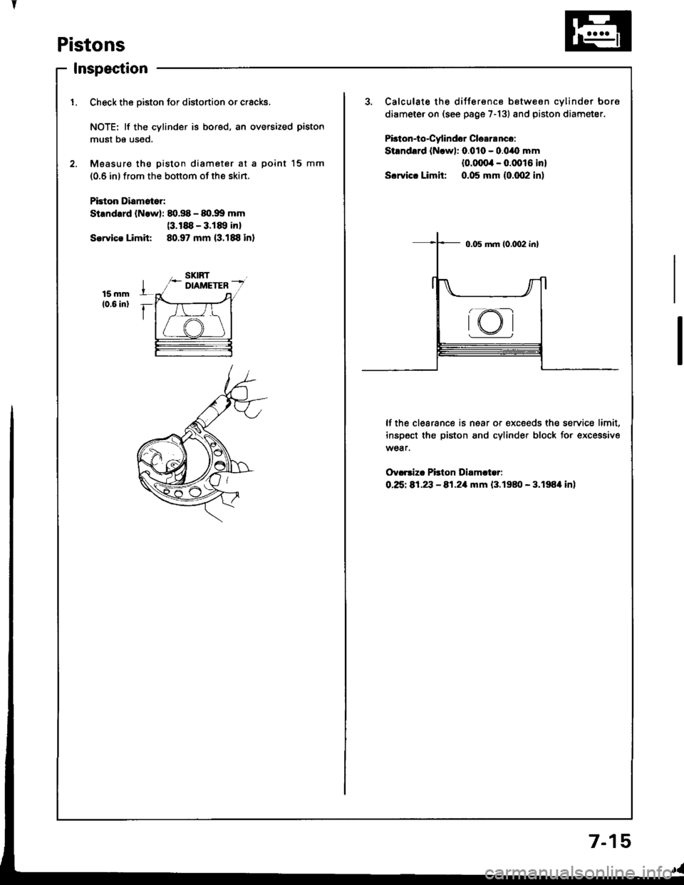
1. Check the oiston for distortion or cracks.3, Calculate the difference betw€on cvlinder bore
diameter on (see page 7-13) and piston diametsr.
Pbton-io"Cy'indor Clea18nco:
Stsndard (Nrwl: 0.010 - 0.0/O mm
{o.ofira - 0.0016 in}
S.rvic. Limit: 0.05 mm {0.002 in)
NOTE: lf the cylinder is bored, an oversized piston
must be used,
2. Moasur€ the piston diameter at a point l5 mm
(0.6 in) from the bottom of the skin.
Pbion Diamat6r:
Standard lNowl: 80.S - 80.99 mm(3.188 - 3.189 inl
Sorvica Limit 80.97 mm (3.188 in)
lf the clearance is near or €xc€eds the service limit,
inspect the piston and cylinder block for excessive
wear.
Ov.rsizc Pilton Diamcter:
O.25t 81,23 - 81.21|rnm {3.1980 - 3.198'l in)
rKI
7-1
Page 161 of 1413
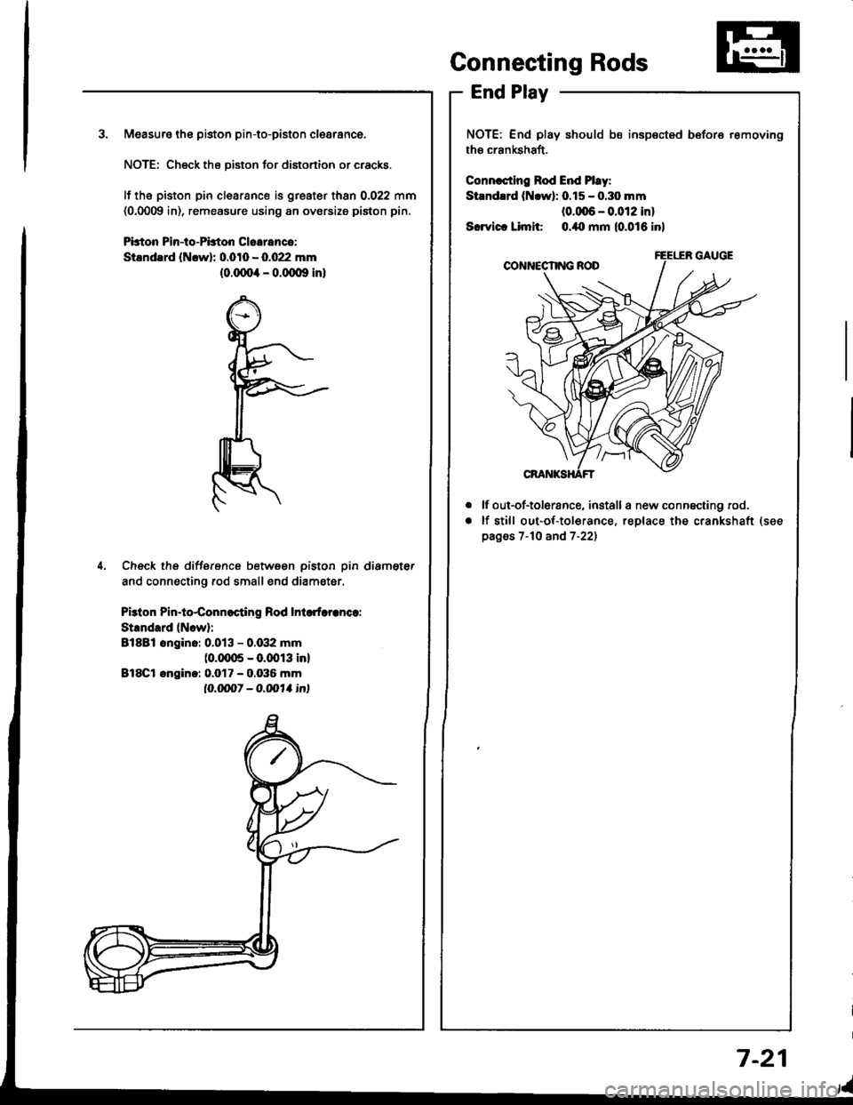
3. Measuro the piston pin-to-piston clearance.
NOTE: Check the Diston for distonion or cracks.
It the piston pin clearance is greater than 0.022 mm(0,0009 in), remeasure using an ovorsize piston pin.
Pbton Pin-to-PLton Cloeranco:
StlndErd (Ncwl: 0.010 - 0.022 mm(0.(xto4 - o.(Xxlg inl
4. Check the difference betwsen piston pin diameter
and connecting rod small end diam€ter.
Pbton Pin-to4onnocting Rod Inlcdaranca:
Strndlrd {Ncw}:
Bl8Bl ongino: 0.013 - 0.G12 mm(0.fiX15 - 0.0013 inl
Bl8Cl cngin.: 0.017 - 0.036 mm
IO.ON1 - O.|,o11 int
Connecting Rods
End Play
NOTE: End play should bs insp€cted before removing
the crankshaft.
Connrcting Rod End Pl.y:
Stlndrrd (Nrwl: 0.15 - o.3o mm(0.(xt6 - 0.012 inl
Scrvict Limit o./to mm (0.016 inl
lf out-of-tolerance, install a new connscting rod.
lf still out-of-to16rance, replace the crankshaft
pages 7-10 and 7-22)
a
a
7-21
Page 162 of 1413
Connecting Rods
Selection
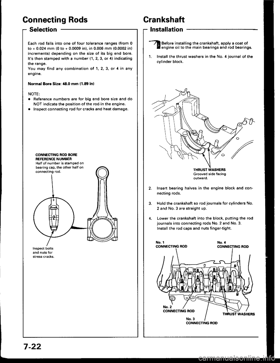
Each rod falls into one of four tolerance ranges (from 0
to + 0.024 mm (0 to + 0.0009 inl, in 0.006 mm {0.0002 in)
increments) depending on the size ot its big end bore.
It's then stamped with a number (1,2,3, or 4) indicating
the range.
You may find any combination ol 1, 2, 3, or 4 in any
engane.
Normsl Boro Sizoi ,18.0 mm 11.89 inl
NOTE:
a Reference numbers are Jor big end bore size and do
NOT indicate the position of the rod in the engine.
. Inspect connecting rod for cracks and heat damage.
CONNECNNG ROD BOREREFERENCE NUMBERHalf oI number is stamped onbearing cap. th€ other halfonconnecting rod.
Crankshaft
lnstallation
Before installing the crankshaft. apply a coat ofengine oil to the main bearings and rod bearings.
1. Install the thrust washers in the No. 4 iournsl of the
cvlinder block.
Grooved side tacingo!tward
Insert bearing halves in the engine block and con-
necting rods.
Hold the crankshaft so rod journals for cylinders No.
2 and No.3 are straight up.
Lower the crankshaft into the block. putting the rod
journals into connecting rods No.2 and No.3.
Install the rod caps and nuts finger-tight,
CONNECNNG ROD
7 -22
Page 225 of 1413
PGM-FIIOLE CONTROLFUEL SUPPLY
INTAKEAIR€MtsstoNCONTROLSELECTRICALLOAODETECTOR
VARIAEIE VALVETIMINC & VALVELIFT ELECTRONICcoNTRO|-SOLENOID
VARIABLE VALVETIMING & VATVEI-IFT ILECTRONICcottTR0tPffESSURE
KNOCKstNsoRFISIGNALFISIGNAT
IOLE AIRc0NTR0r-OTHERIOLECONTROLS
FUELINJECTOR
OTHERFUELSUPPTY
| 1"70s3811.74r 1-76t 1-7611-8211-78| 1-102r 1-97t 1-1 15ll129
Er6t-- -------16l-/-----..Efl-o_,.''\
\.-r-l-t l0 t----i-\t2t I/ --i-\
\-!-/
l22 l/-- j--\t23 l-/--.i-\-t 30 l-,--T-\
\.--r-z
t3r t-/-.--\
\.---l
[|-/----\I 16 t-/ _-i- \
@
@
o@
o@@
oQ)
@a,@@
o@@
@o
o
(JJ
@@@o@
11-3
Page 231 of 1413
How to Read Flowcharts
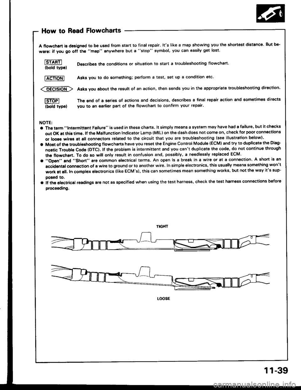
A flowchrrt is dasigned to be us€d fiom start to final repair. lt's like a map showing you the shortest distanco. But be-
ware: if you go off tho "map" anywhere but a "stop" symbol, you can easily get lost
l6rffil Desclibas the conditions or situation to start a troubleshooting flowchart.(bold tyDo)
|TeTiONl Asks you to do something; pedorm a test, set up a condition etc'
<:6Eei6io-fr\> Asks you about the result of an action, then sends you in the appropriste troubleshooting direction.
I-SJTFI The snd of a series ot actions and decisions, describes I tinal repair action and aomotimea diracts
(bold typel you to 8n garlier part of the tlowchart to confirm your repair'
NOTE:
a Tha tarm ,,lntormittgnt Failure" is used in these chans. lt simply means a system may have had a failur6, but it chocks
out OK !t this time. lf th6 Msltunction Indicator Lamp (MlL) on ihe dash does not come on, check for poor connections
or loose wires at all connectors rolated to the cilcuit that you are troubleshooting (see illustration b6low).
a Most ot tho troublashooting flowchans have you reset the Engine Control Module (ECM) and try to duplicate the Disg-
nostic Troubls Cod6 (DTC). lf the problem is intermittent and you c8n't duplicat€ the cod6, do not continus through
the flowchart, To do so will only rosult in confusion and, possibly, a ne€dlessly replaced ECM
a ,,opon,'and ,,short,, are common electrical terms. An open is a break in a wir6 or at a conn€ction. A short is an
accidontal connaction ot a wir€ to ground or to another wire. In simple electronics, this usually means som€thing won't
work at all. In complex electronics (like ECM's), this can sometimes mean something wolks, but not the way it's sup-
poSad to,
a il th6 olectricsl readings are not as specified when using the test harness, check the test harness connoctions bsfore
procooding.
LOOSE
11-39
Page 303 of 1413
Fuel Supply System
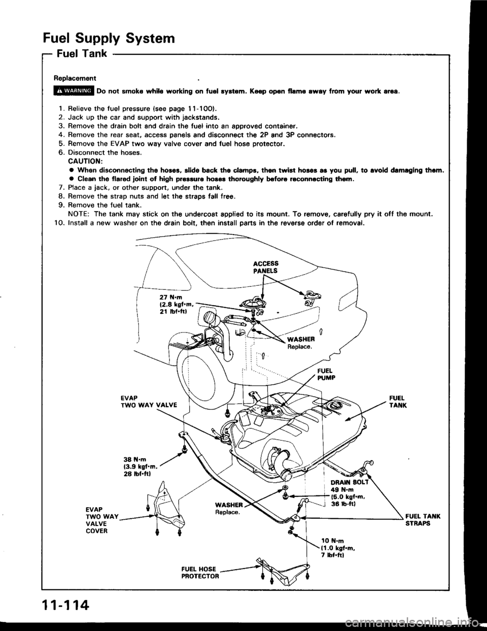
Fuel Tank
Replacement
@ oo not smoke while working on fusl syltem. Koep opon flame rway from your wort ar6a.
1. Relieve the fuel pressure {see page 11-1OO).
2. Jack up the car and support with jackstands.
3. Remove the drsin bolt and drain the fuel into an approved container.
4. Remove the rear seat, access Danels and disconnect the 2P and 3P connectors.
5- Remove the EVAP two way valve cover and tuel hose protector.
6. Disconnect the hoses.
CAUTION:
a Whan disconnacling tho hosos, slide back tho clampr, th6n twist horos as you pull, to lvold drmlglng thcm.
a Clean the tlarod roint ot high plossulo hosos thoroughly brforc roconnccling thsm.
7. Place a jack. or other support, under the tank.
8. Remove the strao nuts and let the straDs tall free.
9. Remove the Juel tank.
NOTE: The tank may stick on the undercoat applied to its mount. To remove, caretully pry it off tho mount,
1O. Install a new washer on the dlain bolt, then install psns in the raverse ordgr ot rsmoval.
FUELPUMP
EVAPTWO WAY VALVE
38 l{.m(3.9 kgt'm,28 rbl.ftl
FUELTANK
EVAPTWO WAYVALVECOVER
FUEL TAI{KSTRAPS
tO t{.mll.O kgt'm,7 lbl.frl
11-114
Page 321 of 1413
Emission Control System
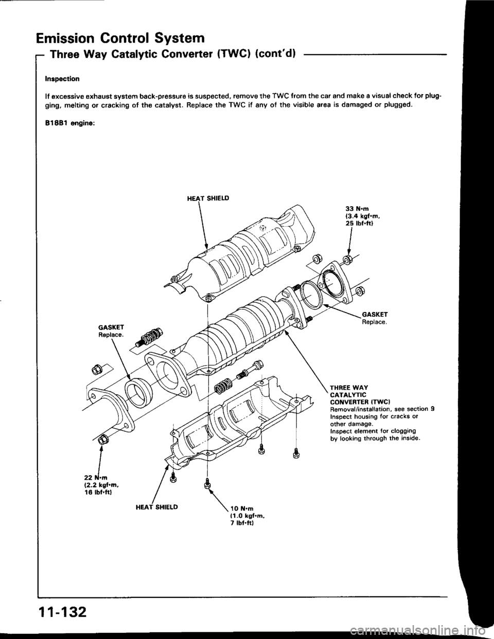
Three Way Catalytic Converter (TWC) (cont'dl
Inspection
lf sxcessive oxhaust system back-pressure is suspected. remove the TWC trom the car and make a visual check for plug-
ging, melting or cracking of ths catalyst. Replace the TWC if any of the visible area is damaged or plugged.
81881 ongino:
TI{REE WAYCATALYTICCONVERTER {TWCIRemovsl/installation, see section 9
Inspect housing for cracks orother damage.Inspect element tor cloggingby looking through the inside.
HEAT SHIELD
11-132
T SHIELO
Page 322 of 1413
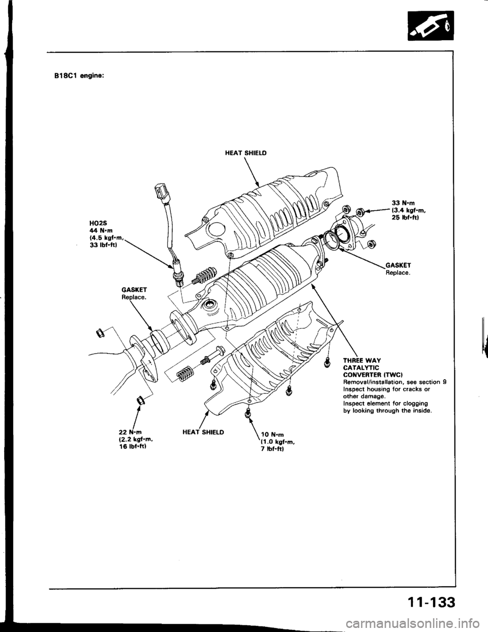
818Cl engine:
HEAT SHIELO
r{
THREE WAYCATALYTICCOI{VEBTEB {TWCIR€moval/installation. sso s€ction 9Inspoct housing tor cracks orothor damage.Inspect elemont for cloggingby looking through the inside.
HEAT SHIELD
11-133