trunk trim HONDA INTEGRA 1994 4.G Workshop Manual
[x] Cancel search | Manufacturer: HONDA, Model Year: 1994, Model line: INTEGRA, Model: HONDA INTEGRA 1994 4.GPages: 1413, PDF Size: 37.94 MB
Page 937 of 1413
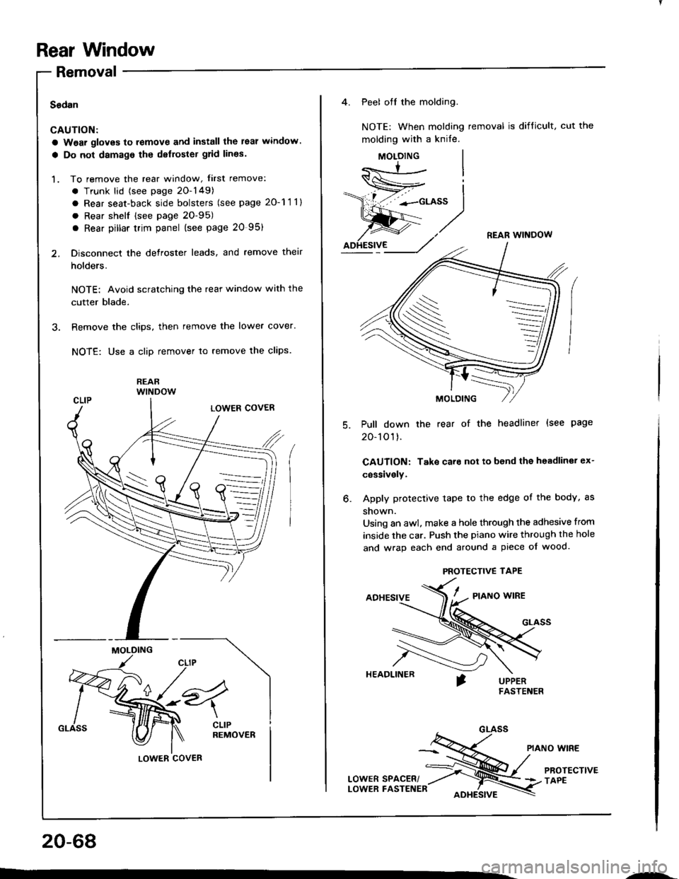
Rear Window
Removal
Sadan
CAUTION:
a Wear gloves to remove and install the leal window.
a Do not damage the delloster grid lines.
1. To remove the rear window, f irst remove:
. Trunk lid {see page 20-149)
a Rear seat-back side bolsters (see page 20-11 1)
. Rear shelf (see page 2O-95)
a Rear pillar trim panel {see page 20 95)
2. Disconnect the defroster leads, and remove their
holders.
NOTE: Avoid scratching the rear window with the
cutter blade.
3. Remove the clips, then remove the lower cover.
NOTE: Use a clip remover to remove lhe clips.
REARwlNDow
MOLDING
LOWER COVER
20-68
---
4. Peel off the molding.
NOTE: When molding removal is difficult, cut the
molding with a knife.
MOLOING
REAR WINOOW
Pull down the rear of the headliner (see page
20-101).
CAUTION: Take care not to bend the headliner ex-
cessively.
Apply protective tape to the edge of the body, as
shown.
Using an awl. make a hole through the adhesive from
inside the car. Push the piano wire through the hole
and wrap each end around a piece of wood.
ADHESIVE/ - a,o*o *'*a
HEADLINER
PIANO WIRE
LowERsPAcER/ ;ru/
PRorEcrtvE
LowER FASTENER oore,srvr \3 rlee
o.
S
PROTECTIVE TAPE
Page 960 of 1413
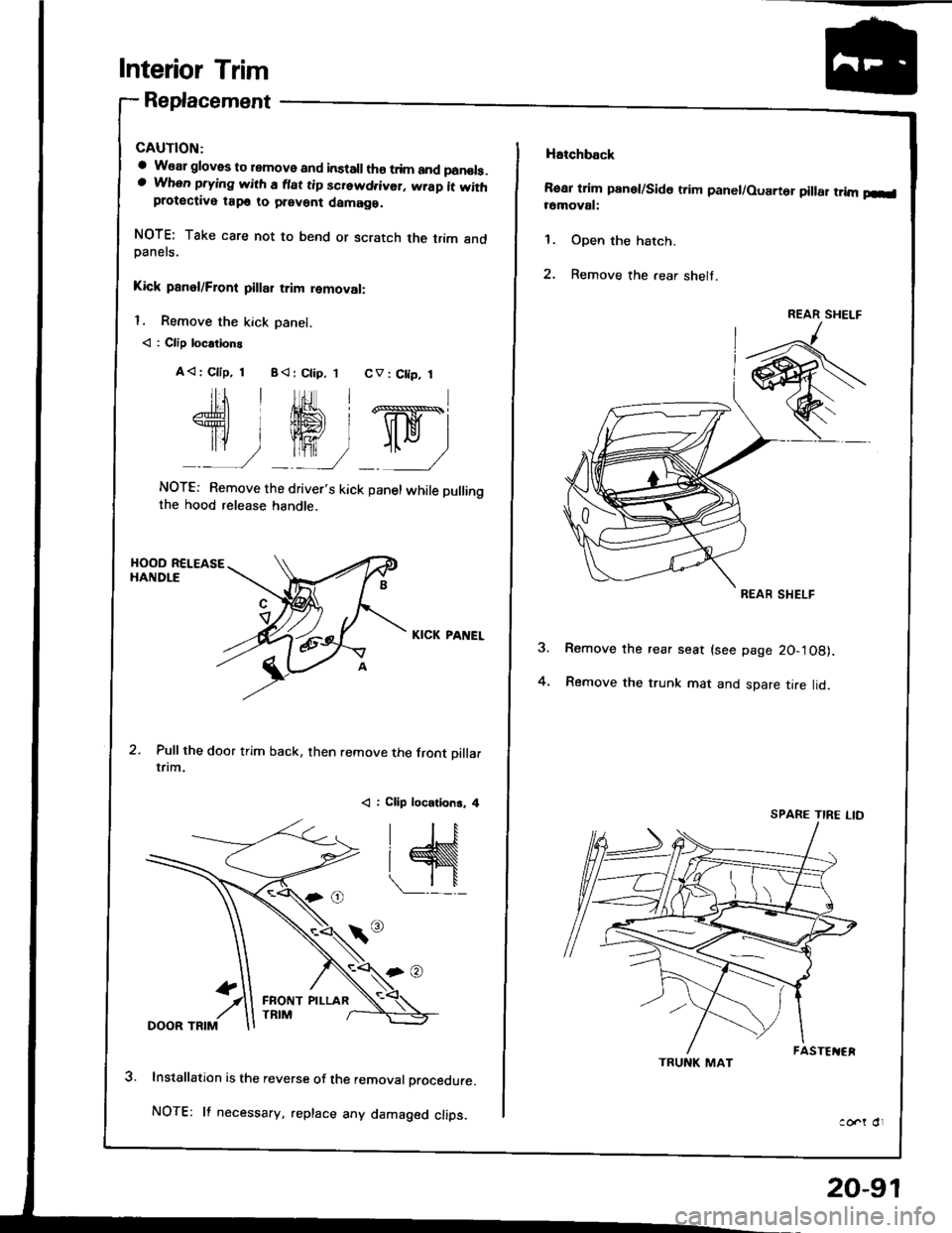
Interior Trim
Replacement
a W€al gloves to remove and installth€ trim and panols.a When prying with a flat tip screwd.ivor. wrap it withprotective tap€ to prevent damaga.
NOTE: Take care not to bend or scratch the trim andDanels.
Kick panel/Front pillar trim removal:
l. Remove the kick Danel.
< : Clip locations
A< | Cllp, 1 B< : Ctip, 1 CV : C[p, 1
Jtl,Ml*
U ry-ry
NOTE: Remove the driver's kick panel while pullingthe hood release handle.
KICK PANEL
Pull the door trim back, then remove the front oillarrflm.
< : Clip locations, 4
lnstallation is the reverse of the removal procedure.
NOTE: lf necessary, .eplace any damaged clips.
FRONT PILLAR
20-91
Hatchback
Rear trim panet/Side trim panel/Ouarter pillar trim p-l16moval:
1. Open the hatch.
2. Remove the .ear shelt.
Remove the rear seat (see page 20-'l08).
Remove the trunk mat and spare tire lid.4.
ao..t dr
REAR SHELF
REAR SHELF
TRUNK MAT
SPARE TIRE LID
Page 966 of 1413
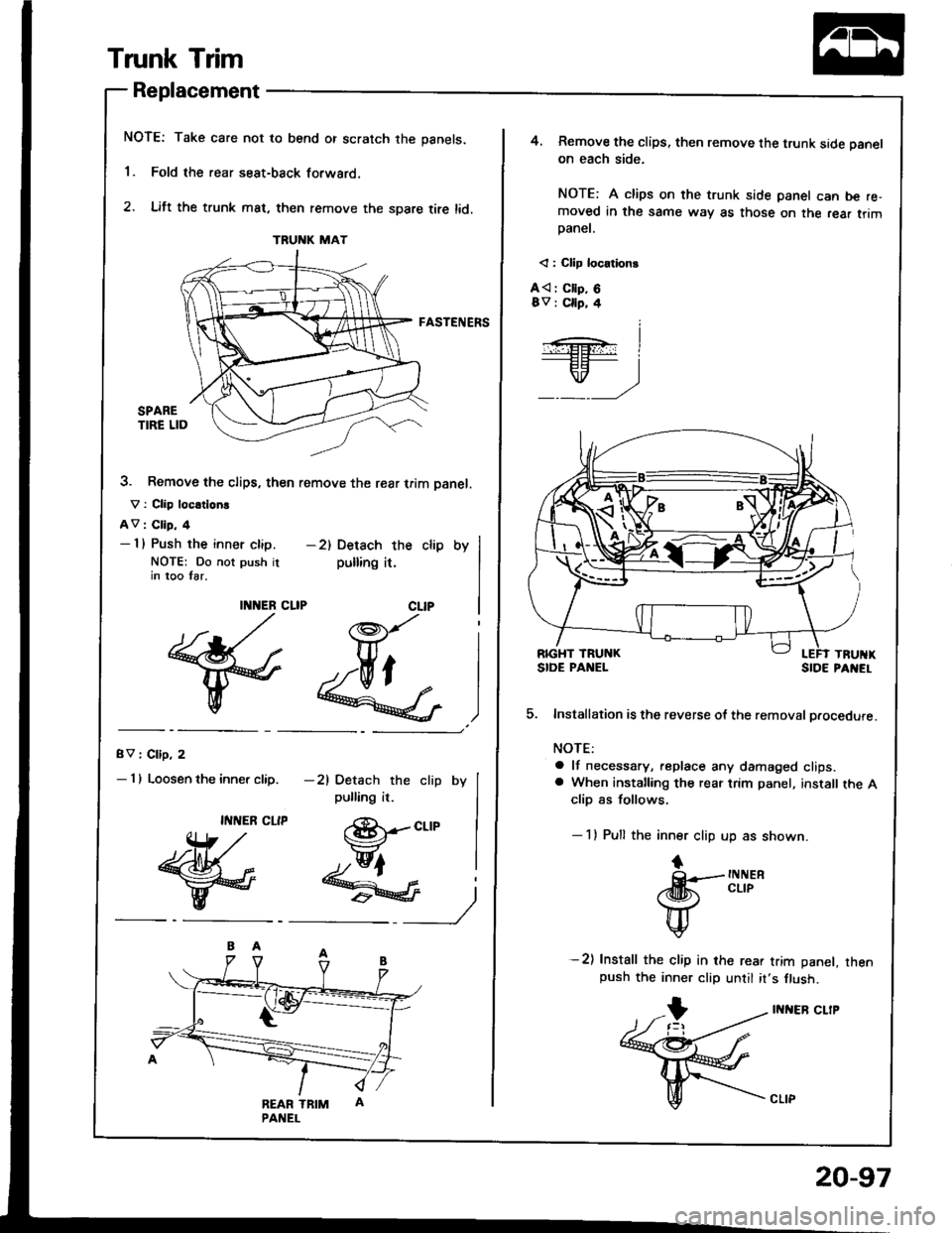
Trunk Trim
Replacement
NOTE: Take care not to bend or scratch the panels.
'1. Fold the rear seat-back forwaro.
2. Lift the trunk mat, then remove the spare tire lid.
FASTENERS
3. Remove the clips, then remove the rear trim Danel.
V : Clip loc.tlorE
AV : Clip, 4- I l Push the inner clip.
NOTE: Do not push itin too Iar.
gV I Cllp, 2
- I I Loosen the inner clip.
TRUNK MAT
-2) Detach the clip by
pulling it.
Y_)
(8r-ct-tp
hfr
)J"'J..&G 4
eEdf,
II{NER
{* ,/
w
II{NEB CLIP
ffi
-21 Detach the clip by
pulling it.
@lqFl
-- t"
4. Remove the clips, then remove the trunk side panel
on each side.
NOTE: A clips on the trunk side panel can be re-moved in the same way as those on the rea. trimpaner.
< : Cllp locationt
A{ : Cllp, 68v : Cllp, 4
Installation is the reverse ot the removal procedure.
NOTE:
a lf necessary, replace any damaged clips.a When installing the rear trim panel, install the Aclip as follows.
- 1) Pull the inner clip up as shown.
tF tNt{ER
rd[h cLrP
H
v
-2) Install the clip in rhe rear trim panel, rhenpush the inner clip until it,s flush.
INI{ER CLIP
5.
20-97
Page 989 of 1413
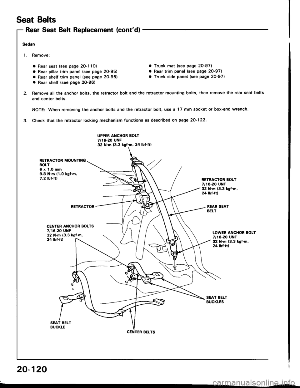
Rear Seat Belt Replacement (cont'd)
a Rear seat {see page 20-1 10) a Trunk mat (see page 20-97}
a Rear pillar trim panel (see page 20-951 a Rear trim panel {see page 20-971
a Rear shelf trim panel (see page 20-95) . Trunk side panel (see page 20-97)
. Rear shelf (see pag€ 20-96)
Remove all the anchor bolts, the retractor bolt and the retractor mounting bolts, then remove the rear s€at belts
and center belts.
NOTE: When removing the anchor bolts and the retractor bolt, use a 17 mm socket or box-end wrench.
Check thst the retractor locking m€chanism tunctions as described on page 2O-122'
UPPER ANCHOR BOLT7/16-20 UNF32 N.tn (3.3 kgf'm, 24 lbl ft)
RETRACTOR MOUNTINGBOLT6 x 1.0 mm9.8 il.m (1.0 kgt.m,7.2 tbt.tllRETRACTOR BOLT7/16-20 UNF32 .m (3.3 kgl.m,24 tbt.ft)
RETRACTORREAR SEATBELT
Seat Belts
Sodan
'I . Remove:
20-120
CENTER AI{CHOR BOLTS7/16-20 UNF32 N.m (3.3 ksl'm,LOWER ANCHOR BOLT7/16-20 UNF32 N.m (3.3 kgf .m,
24 tbf.ftl
24 lbl ftl
CENTER BELTS
Page 1011 of 1413
Bumpers
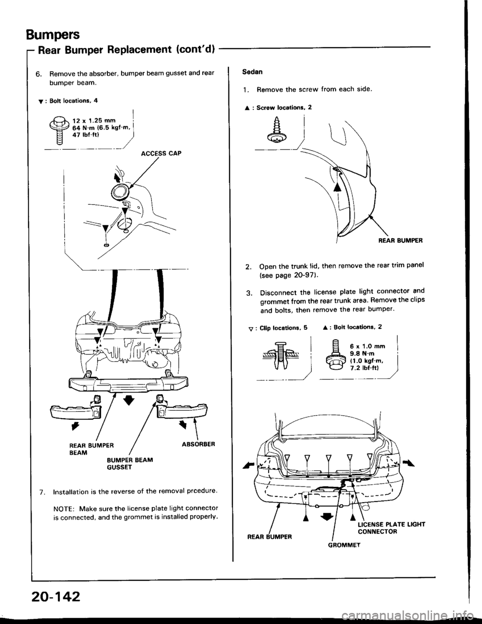
Rear Bumper Replacement (cont'dl
6. Remove the absorber, bumper beam gusset and rear
bumper beam.
y: Bolt localions, 4
12 x 1.25 mm I
64Nm{65kgfm,I* "r:,
)ACCESS CAP
LlF/d,rft
REAR EUMPERBEAMEUMPER BEAMGUSSET
lnstallation is the reverse of the removal prcedure.
NOTE: Make sure the license plate light connector
is connected, and the grommet is installed properly,
20-142
Sadan
1. Remove the screw from each side
: Sciow locations, 2
REAR BUMPER
2. ODen the trunk lid, then remove the rear trim panel
(see page 20-97).
3. Disconnect the license plate light connector and
grommet from the rear trunk atea. Remove the clips
and bolts, then remove the rear bumper'
v: Cllp loc.tions, 5 : 8ok locations, 2
€l
#.,1
9.8 N.m il1.O kgl m, I7.2 rbr.ft) J
6 x 1.0 mm I
GBOMMET
Page 1022 of 1413
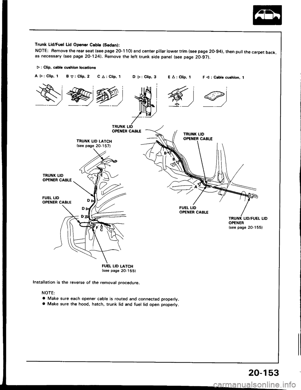
Trunk Lid/Fuol Lid Opan.. Cablo (Sodanl:
NOTE: Remove the rear seat {see page 2O-1 10) and center pillar lowertrim (see page 20-94}, then pullthe carDet back.as necessa.y (see page 2O-1241. Remove rhe left trunk side panel (see page 20-97).
> : CliD, c.bla cu.hion locstlon!
A >: Cllp, 1 BV:Clip,2 C A: Clip,,tD >: Clip,3F < : C.ble culhlon, 1
ws@:
ffi;
7--
TRUITIK LID LAICH(s€e p6ge 20-157)
FUEL LID
FUEI. LID LATCH(soo pago 20_'|55)
Installation is the reverse of the removal orocedure.
NOTE:
a Make sure each opener cable is routed and connected properly.a Make sure the hood, hatch. trunk lid and fuel lid open properlt.
EArCllp, 1
6,1
OPENER{se6 page 20-1 55)
20-153
Page 1024 of 1413
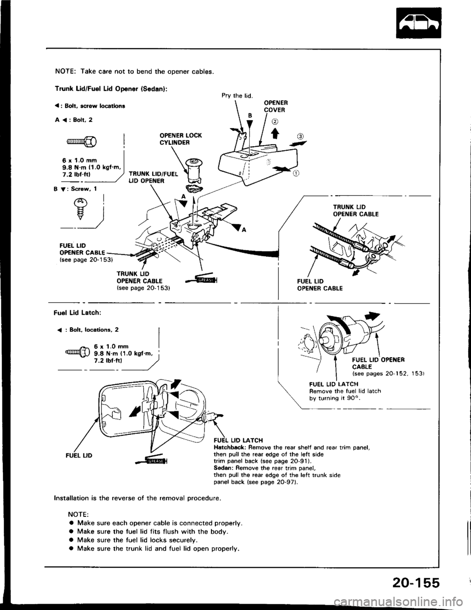
NOTE: Take care not to bend the opener cables.
Trunk Lid/Fuel Lid Oponer {Sodan}:
< : Bolt, scrow locatlon!
A<:Bolr,2
OPENER LOCKCYLINDER
TRUNK LID/FUELLID OPENER
B V: Scrow, 1
AI-}{- IH. I
_:_)
FUEL LID
Pry the ljd.OPENERCOVER
o
to-*rr*@
6 r 1.0 mm
()t
OP€NER CABLE(seo page 2O-153)
TRUNK LIDOPENER CABLE(see page 20-1 53)
9.8 N m 11.O kgl m,
Fuol Lid Lstch:
< : Boh, locotions, 2
6r1.0mm
FUEL LID OP€NERCAALE(see pages 20-152, 153)
9.8 N m 11.0 ksl'm, i7 '2 tbt'''l
------,//
FUEL LID
lnstallation is the reverse of the removal orocedure.
NOTE:
a Make sure each opener cable is connected properly.
a Make sure the fuel lid fits flush with the body.
a Make sure the tuel lid locks securelv.
a Make sure the trunk lid and fuel lid open properly.
LIO LATCHHatchbock: Remove the rear shelf and rear trim oanel.then pull the rear edge ot the lett sidetrim panel back (soe page 2O-91).Sodan: Remove the rear trim panel,then pull the rear edge of the left trunk sidepanel back {see page 2O-971.
FUEL LIO LATCHRemove the fuel lid latchby turning it 90o.
20-155
Page 1299 of 1413
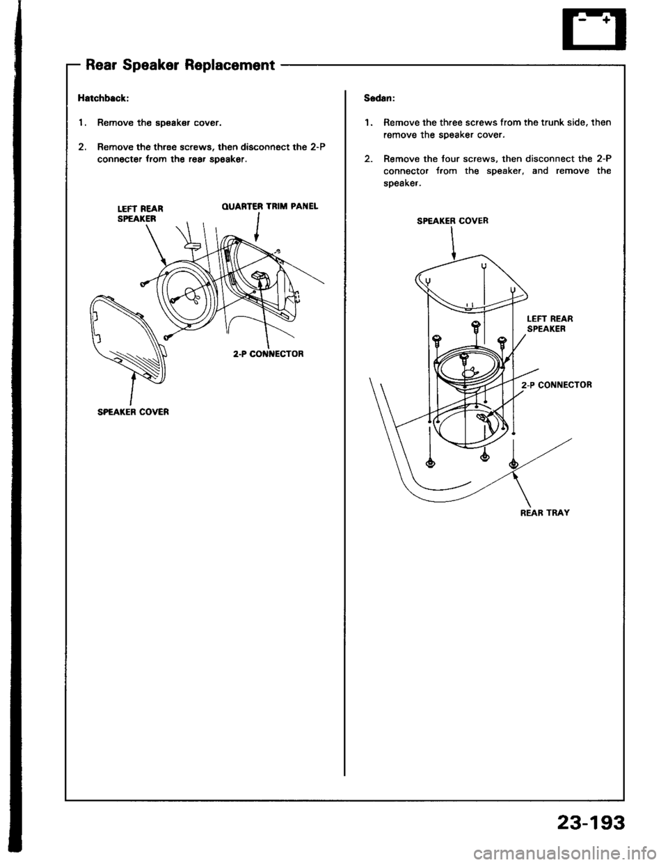
Rear Speaker Replacement
Hatchback:
1. Remove the sDsaker cover.
2. Remove the three screws, then disconngct the 2-P
connocter trom the rear spoakor.
1.Remove the three screws from the trunk side, then
remove the soeaker cover.
Remove the tour screws, then disconnect the 2-P
connector t.om the s9eaker, and remove the
soeake,.
LEFT REARSPEAKER
OUARTER
,r-- I
TRIM PAI{EL
LEFT REARSPEAKEN
2-P CONNECTON
SPEAKER COVER
REAB TRAY
SPEAKER COVER
23-193
Page 1300 of 1413
Stereo
Power
Sound
Antenna
System
Motor Test
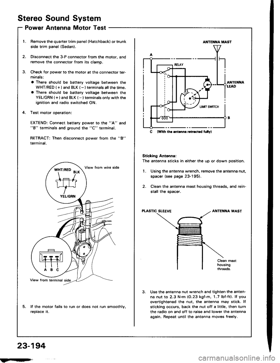
Remove the quarter trim panel (Hatchback) or trunk
side trim panel (Sedan).
Disconnect the 3-P connector from the motor, and
remove the connector from its clamD.
Check for power to the motor at the connector ter-
minals:
a There should be battery voltage between the
WHT/RED (+l and BLK {-} terminals all thetime.a There should be battery voltage between the
YEL/GRN {+) and BLK (-} terminals onlv with the
ignition and radio switched ON.
Test motor oDeration:
3.
4.
EXTEND: Connect battery power to the "A"
"B" terminals and ground the "C" terminal.
8no
"4"RETRACT: Then disconnect power trom the
terminal,
lf the motor fails to run or does not run smoothlv,
reDtace tr.
*ft'^to
?r*
TIFIT*r'
YEL/GRN
AI{TE T{A MAST
AI{TEI{I{ALEAD
C ftYhh lha lnLnn. r.tr.ci.d t|Ilyl
Sticking Ant6nna:
The antenna sticks in either the up or down position.
1.Using the antenna wrench, remove the antenna nut,
spacer (see page 23-195).
Clean the antenna mast housing threads, and rein-
stall the soacer.
PLASTIC SLEEVEAIITENNA MAST
Cloan masthousingthroads.
Use the antenna nut wrench and tighten the anten-
na nut to 2.3 N.m (0.23 kgf-m, 1.7 lbf-tt). lJ you
overtightened the nut. the antenna may stick. lf
sticking occurs, back the nut off a little, then turn
the radio on and off to raise and lower the antenna
again. Repeat until the antenna moves treely.
23-194
fmft,
Page 1302 of 1413
Stereo Sound
Power Antenna
System
Motor Replacement
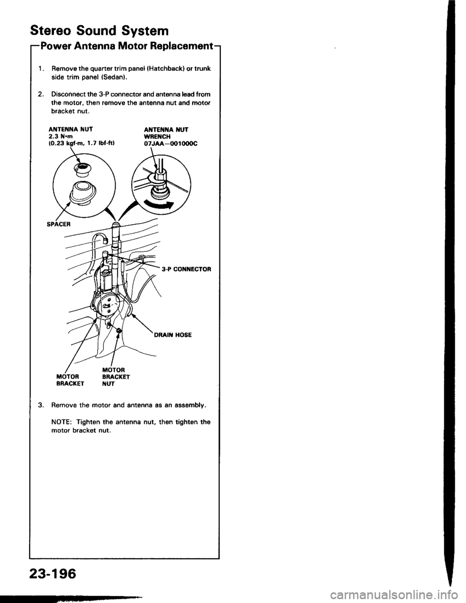
1.Remove tho quart€r trim panel (Hatchback) or trunk
side trim panel (Sedan).
Disconnect the 3-P connector and antenna lead trom
the motor, then remove the antenna nut and motor
bracket nut.
AI{TENNA 1{UT2.3 l{.mAT{TEI{]{A I{UTWBEI{CHoTJAA-OOlo(xrc
3+CO ECTOR
DRAI HOSE
MOTORBRACKETTUT
3.Remove the motor and antenna as an assemblv.
NOTE: Tighten the antenna nut, then tighten tha
motor bracket nut.
23-196