sensor HONDA INTEGRA 1998 4.G Owners Manual
[x] Cancel search | Manufacturer: HONDA, Model Year: 1998, Model line: INTEGRA, Model: HONDA INTEGRA 1998 4.GPages: 1681, PDF Size: 54.22 MB
Page 435 of 1681
Description
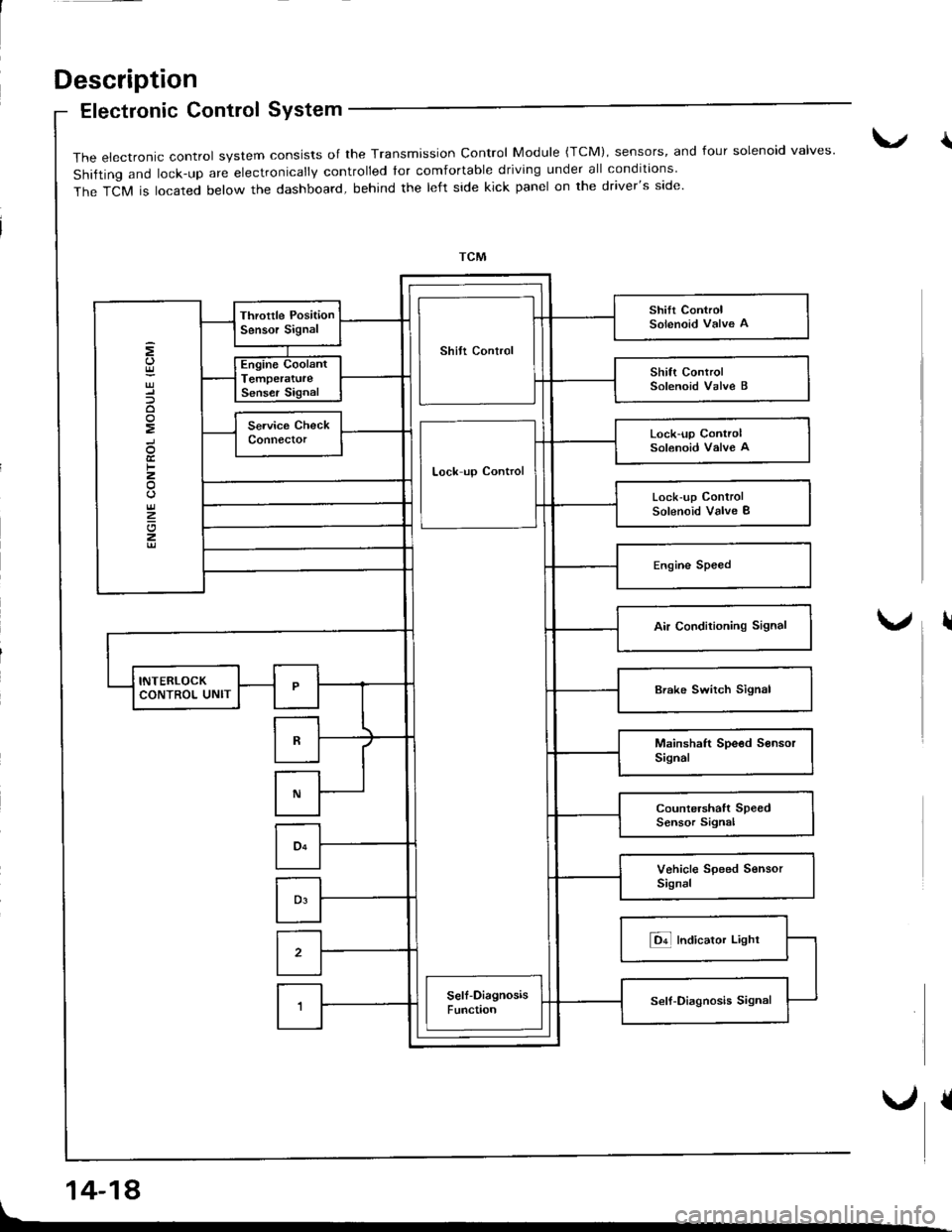
Electronic Control SYstem
14-18
{The electronic control system consists of the Transmission control Module {TcM), sensors, and four solenoid valves'
shifting and lock-up are electronically controlled tor comfortable driving under all conditions
The TCM is located below the dashboard, behind the left side kick panel on the driver's side.
Shilt Control
Lock-up ControlSolenoid Valve A
Lock up Control
Lock-up ControlSolenoid Valve I
I
Page 436 of 1681
Lock-uD Control
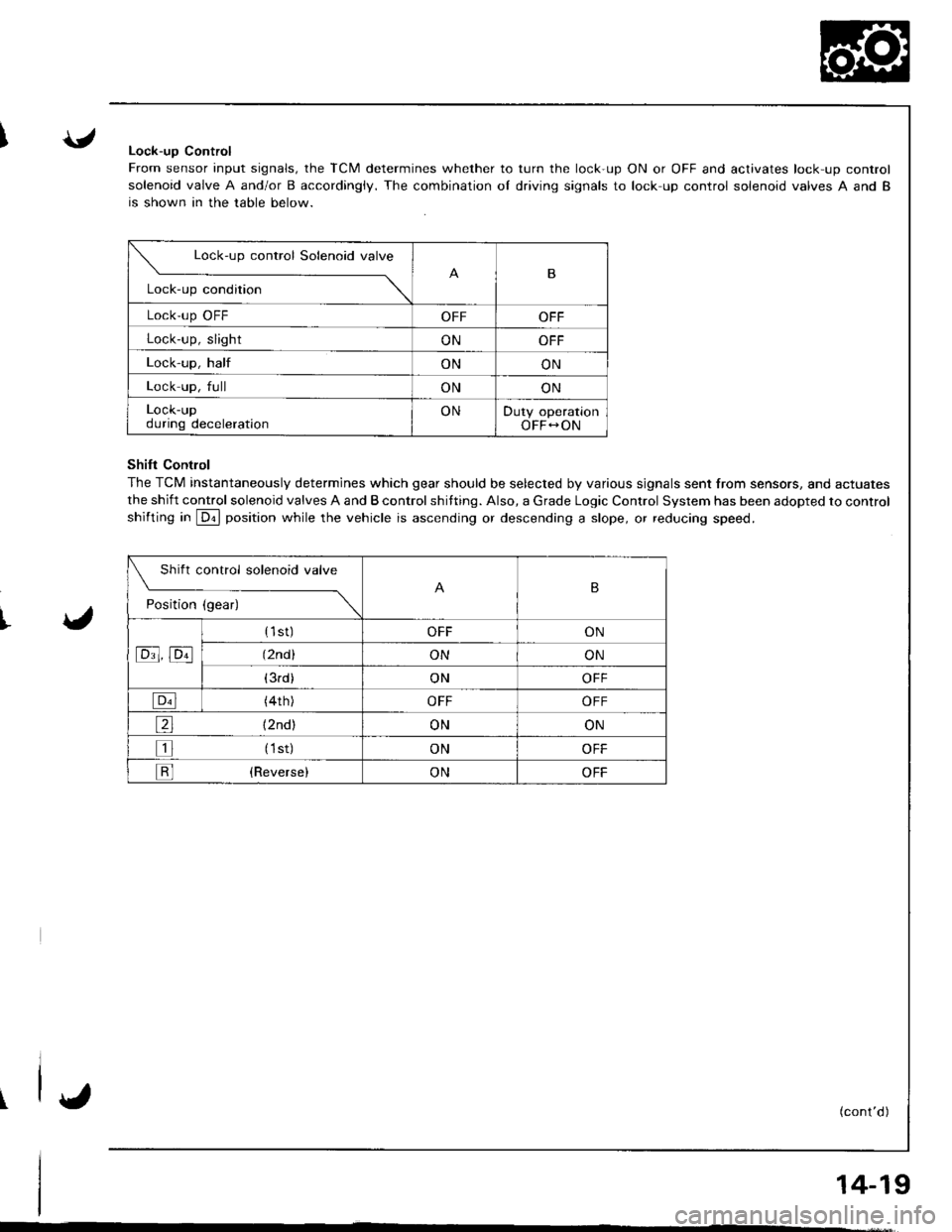
From sensor input signals, the TCM determines whether to turn the lock-up ON or OFF and activates lock-up control
solenoid valve A and/or B accordingiy. The combination oI driving signals to lock up control solenoid valves A and B
is shown in the table below.
ShiIt Contlol
The TCM instantaneously determines which gear should be selected by various signals sent from sensors, and actuates
the shift control solenoid valves A and B control shifting. Also, a Grade Logic Control System has been adopted to control
shifting in @ position while the vehicle is ascending or descending a slope, or reducing speed.
w"'u"
Lock-up condition
-\B
Lock'up OFFOFFOFF
Lock-up, slightONOFF
Lock-up, halfONON
Lock up, fullONON
LOCK-Upduring decelerationONDuty operationOFF-ON
Shift control solenoid valve
t"dil"" d;------\
B
tc!t' tcll
{1st)OFFON
(2nd )ONON
(3rd)ONOFF
{4th)OFFOFF
e {2nd)ONON
tr (1st)ONOFF
tr (Reverse)ONOFF
I'
(cont'd)
14-19
Page 437 of 1681
Description
Elestronic Control System (cont'd)
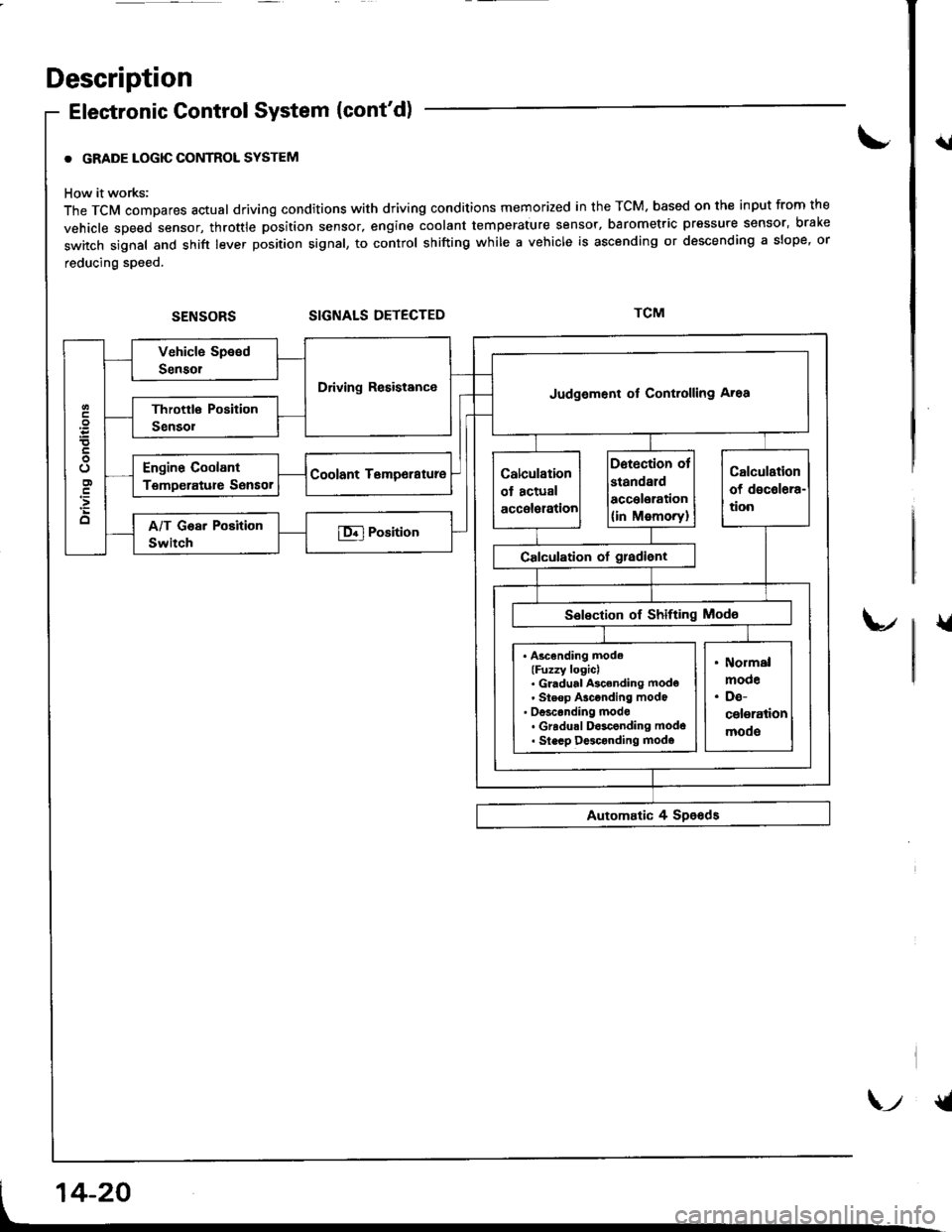
. GRADE LOGIC CONTROL SYSTEM
How it works:
The TCM compares actual driving conditions with driving conditions memorized in the TCM. based on th€ input from the
vehicle speed sensor, throttle position sensor, engine coolant temperature sensor, barometric pressure sensor, bral(e
switch signal and shift lever position signal, to control shifting while a vehicle is ascending or descending a slope, or
reducing speed.
SIGNALS DETECTED
{l
{
Driving ResistanceJudgement of Controlling Aroa
. Ascending mode(Fuzzy logicl. Gl.dual Ascending mode' Steop Asconding mode' oesconding mode. Gradu.l D$conding modo. Slecp D$conding modo
\-t {t
Page 462 of 1681
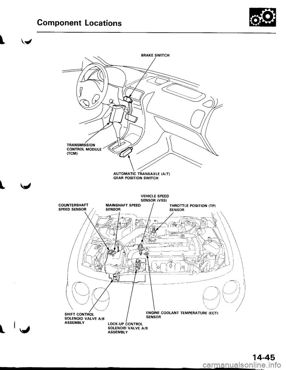
Component Locations
"/,4
'JJ-N
{7v
A0t
\ /
t
AUTOMATIC TRANSAXLE IAiTIGEAR POSITION SWITCH
VEHICLE SPEEDSENSOR {VSSt
COUNTERSHAFTSPEED SENSORMAINSHAFT SPEEDSENSORTHROTTLE POSITIOT{ {TPI
e
SHIFT CONTROLSOLENOID VALVE A/BASSEMBLY
I
- ::::i ---l
1445
Page 464 of 1681
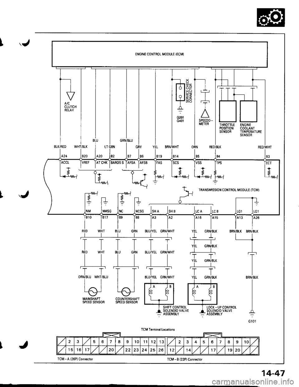
'.J
THROTTLErcsm0NSENSOR
ENGINECOOLANTTEMPERATURESENSOR
WHT/BLKBLK/RED
820424
OBNREO/BLK
84
J
MAINSHAFI COUNTERSHAFISPEED SENSOR SPfED SENSOR
I SHIFT CONTROL I LOCK -UP CONTBOL
+135Eil,?1o'uo'u' 4i85El,o''P'uo'u'
TCM T6nninal locations
TCM -B l22P)Conn€ctor
VREF IATCHK IBASOSS IAFSA IAFSB IFAS ISCS
----T;- t-T-*
+.. | +.., I + ,+
l+ | J l/vt-l .i{-'1M-l L-{-lr^/t-lt't'/!-?
*\::
r--rr!\.1 -r!\./ rartsurssrot coNTFoL M'DULE tTcMr
ltEltn r' -rrt= t= t? t=
NMSG INC INCSG ISH A ISH B ILC A ILC B
576I101112578I10
151617,/1,/20251214,/1,/171920,/1,/J
TCM -A (26P1 Connector
14-47
Page 466 of 1681
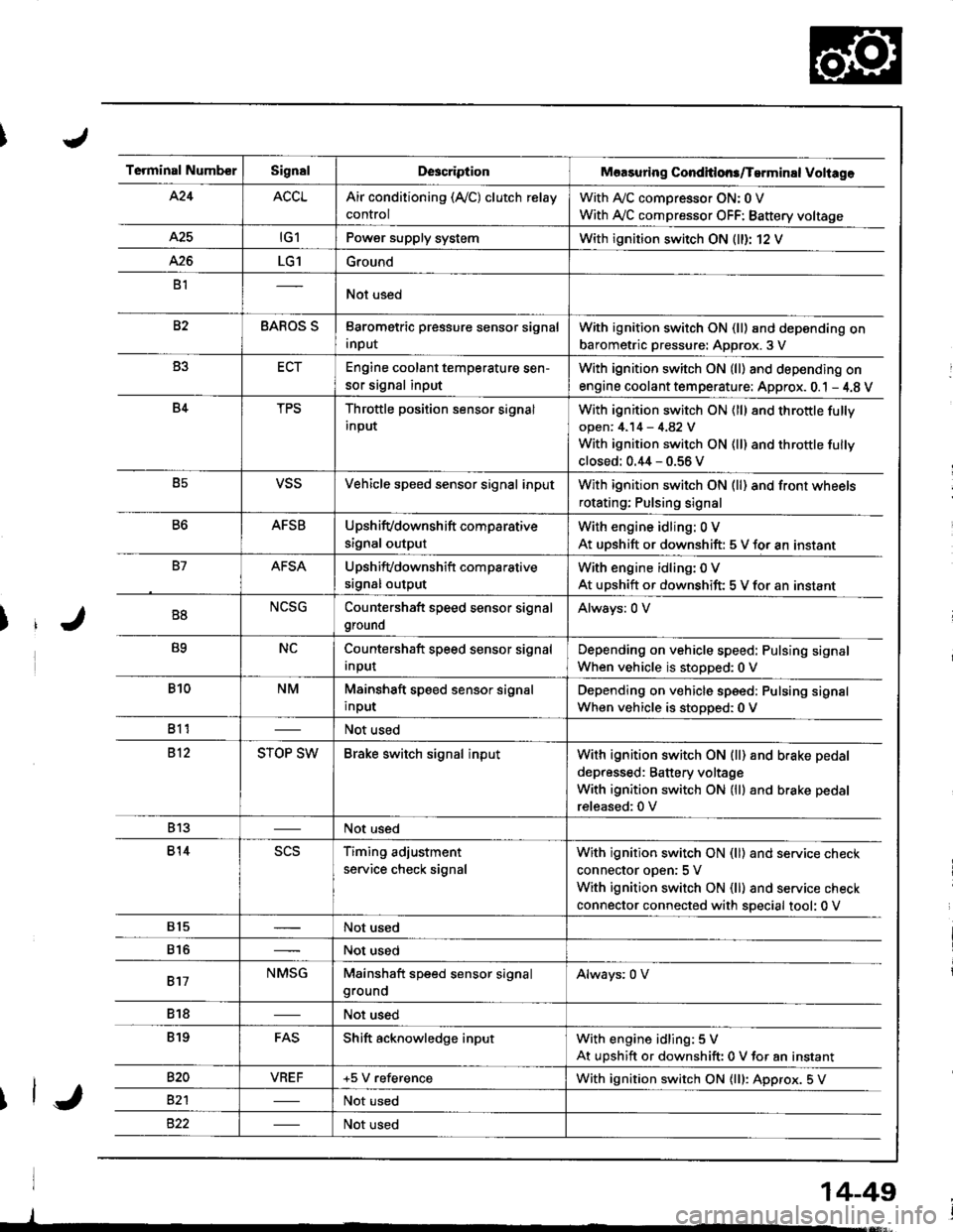
Terminal NumberSignalDescriptionMaasuring Conditlons/Tarminal Voliage
424ACCLAir conditioning (Ay'C) clutch relay
control
With A,/C comDressor ON: 0 V
With Ay'C compressor OFF: Battery voltage
A25tG1Power supply systemWith ignition switch ON (ll)r 12 V
426LG1Ground
B1Not used
82BAROS SBarometric pressure sensor signal
input
With ignition switch ON (ll) and depending on
barometric pressure: Approx. 3 V
B3ECTEngine coolant temperature sen-
sor signal input
With ignition switch ON (ll) and depending on
engine coolant tem perature: Approx. 0.1 - 4.8 V
B4TPSThrottle position sensor signal
input
With ignition switch ON (ll) 8nd throttle fully
open: 4.14 - 4.82 V
With ignition switch ON (ll) and throttle fully
closed: 0.44 - 0.56 V
B5VSSVehicle speed sensor signal inputWith ignition switch ON (ll) and front wheels
rotating; Pulsing signal
B6AFSBUpshifvdownshift comparative
signal output
With engine idling: 0 V
At uDshift or downshift: 5 V for an instant
B7AFSAUpshifvdownshift com parative
srgnal output
With engine idling: 0 V
At upshift or downshift: 5 V for an instant
B8NCSGCountershaft speed sensor signal
ground
Always: 0 V
B9NCCountershaft speed sensor signal
Input
Depending on vehicle speed: Pulsing signal
When vehicle is stopped:0 V
B10NMMainshaft speed sensor signal
input
Depending on vehicle speed: Pulsing signal
When vehicle is stoDoed: 0 V
811Not used
812STOP SWBrake switch signal inputWith ignition switch ON {ll) and b.ake pedal
depressed: Battery voltage
With ignition switch ON (lll and brake pedal
released:0 V
813Not used
814scsTiming adjustment
service check signal
With ignition switch ON (ll) and service check
connector oDen:5 V
With ignition switch ON (ll) and service check
connector connected with special tool: 0 V
815Not used
816Not used
817NMSGMainshaft speed sensor signalgroundAlways: 0 V
818Not used
819FASShift acknowledge inputWith engine idling: 5 V
At upshift or downshift: 0 V for an instant
820VBEF+5 V referenceWith ignition switch ON {lll: Approx. 5 V
82'lNot used
Not used
14-49
Page 471 of 1681
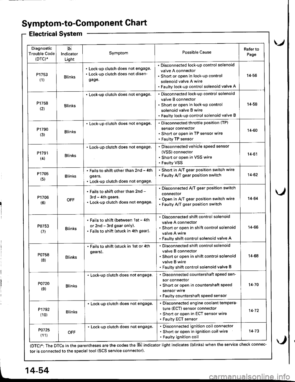
Diagnostic
Trouble Code(Drc)*
,94
lndicator
Light
SymptomPossible CauseRefer to
Page
P1153(1)Blin ks
Lock-up clutch does not engage,
Lock-up clutch does not disen-
gage.
Disconnected lock-up control solenoid
valve A connector
Short or open in lock-uP control
solenoid valve A wire
Faulty lock-up control solenoid valve A
14-56
P1758
t2lBlinks
. Lock-up clutch does not engage.Disconnected lock-up control solenoid
valve B connector
Short or open in lock-uP control
solenoid valve B wire
Faulty lock-up control solenoid valve B
14-58
P1790(3)Blinks
. Lock-up clutch does not engage.Disconnected throttle position (TP)
sensor connector
Short or open in TP seflsor wire
Faulty TP sensor
14-60
P1191(4)Blinks
. Lock-up clutch does not engage.Disconnected vehicle speed sensor
{VSS} connector
Shon or open in VSS wire
Faulty VSS
14-61
P1705
(5)Blinks
. Fails to shift other than 2nd - 4th
gears.
. Lock-up clutch does not engage.
. Shod in AvT gear position switch wire
. Faulty A,/T gear position switch14-62
P1706(6)OFF
' Fails to shift other than 2nd -
3rd - 4th gears.
. Lock-up clutch does not engage.
Disconnected A/T gear position switch
connector
Open in A/f gear position switch wire
Faulty A/f gear position switch
14-64
P0753
(71Blinks
. Fails to shift (between 1st - 4th
or 2nd - 3rd gear only).. Fails to shift (stuck in 4th gear).
Disconnected shift control solenoid
valve A connector
Short or open in shift control solenoid
valve A wire
Faulty shift control solenoid valve A
14-66
P0758(8)Blinks
. Fails to shift (stuck in 1st or 4th
gears).
Disconnected shift control solenoid
valve B connector
Short or open in shift control solenoid
valve B wire
Faulty shift control solenoid valve B
14-68
P0120(9)Blin ks
Lock-up clutch does not engage.Disconnected countershaft speed sen-
sor connector
Short or open in countershaft speed
sensor wrre
Faulty countershaft speed sensor
1+10
P1192
00)Blinks
. Lock-up clutch does not engage,Disconnected engine coolant tempera-
ture (ECT) sensor connector
Short or open in ECT sensor wire
Faulty ECT sensor
14-72
P0725
{1 1)OFF
Lock-up clutch does not engage.Disconnected ignition coil connector
Short or open in ignition coil wire
Faulty ignition coil
14-73
Symptom-to-ComPonent Chart
Electrical System
(DTC)*: The DTCS in the parentheses are the codes the E indicator light indicates {blinks) when the service check connec-
tor is connected to the special tool (SCS service connector)
4-54
Page 472 of 1681
u.drrf,,
J
J
J
14-55
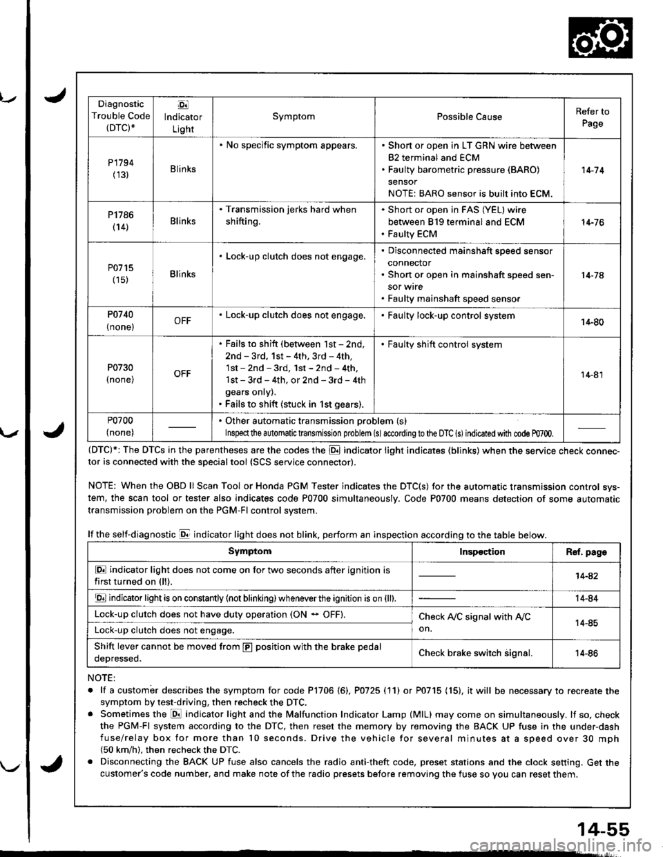
Diagnostic
Trouble Code(DTC).
Ej
lndicator
Light
SymptomPossible CauseRefer to
Page
P1794
(131Blinks
. No specific symptom appears.. Short or open in LT GRN wire between
82 terminal and ECM. Faulty barometric pressure (BARO)
sensor
NOTE: BARO sensor is built into ECM.
't 4-7 4
P1786
(14)Blinks
. Transmission jerks hard when
shifting.
Short or open in FAS (YEL) wire
between 819 terminal and ECM
Faulty ECM
14-76
P0715
(15)Blinks
. Lock-up clutch does not engage,Disconnected mainshaft speed sensor
connector
Short or open in mainshaft speed sen-
sor wrre
Faulty mainshaft speed senso.
14-74
P0740
{ none,OFF. Lock-up clutch does not engage.Faulty lock-up control system14-80
P0730
I none,
. Fails to shift (between lst - 2nd,
2nd - 3rd, 1st - 4th. 3rd - 4th,
1st - 2nd - 3rd, 1st - 2nd - 4th,
1st - 3rd - 4th, or 2nd - 3rd - 4th
gears onry).. Fails to shift (stuck in 1st gears).
. Faulty shift control system
14-81
P0700
(none)
. Other automatic transmission problem (s)
Inspeclthe a utomatic transmission problem (s)accordingto the DTC (s)indicated with code m700.
(DTC)*: The DTCS in the parentheses are the codes the E indicator light indicates (blinks) when the service cnecK connec-tor is connected with the sDecialtool {SCS service connector).
NOTE: WhentheOBDll Scan Tool orHonda PGM Tester indicates the DTC(S) for the automatic transmission control sys-
tem, the scan tool or tester also indicates code P0700 simultaneously. Code P0700 means detection of some automatic
transmission problem on the PGM-Fl control system.
lf the self-diagnostic E indicator light does not blink. perform an inspection according to the table below.
NOTE:
. lf a custombr describes the symptom for code P1706 (6), P0725 (11) or P0715 (15), it will be necessary to recreate the
symptom by test-driving, then recheck the DTC,. Sometimes the E indicator light and the Malfunction Indicator Lamp (MlL) may come on simultaneously. lf so, check
the PGM-Fl system according to the DTC, then reset the memory by removing the BACK UP fuse in the under-dash
fuse/relay box for more than l0 seconds. Drive the vehicle for several minutes at a speed over 30 mph(50 km/h). then recheck the DTC.
. Disconnecting the BACK UP fuse also cancels the radio anti-theft code, preset stations and the clock setting. Get the
customer's code number, and make note of the radio presets before removing the fuse so you can reset them.
SymptomInspectionR€f. page
E indicator light does not come on for two seconds after ignition is
first turned on (ll).14-42
E indicator light is on constantly (not blinking) wheneverthe ignition is on {ll).14-84
Lock-up clutch does not have duty operation (ON - OFF).Check A,/C signal with Ay'C
on.14-85Lock-up clutch does not engage.
Shift lever cannot be moved from E position with the brake pedal
oeDresseo.Check brake switch signal.14-86
Page 477 of 1681
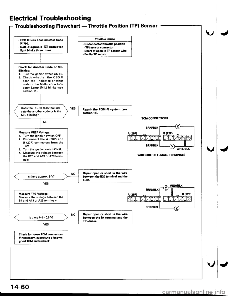
Electrical Troubleshooting
Troubleshooting Flowchart - Throttle PositionITP}Sensor
Po3Cblc C!us.
. Dirc.nn.c.t d throttlo pothion
lTPl ranaor connac'tor. Shon of opan in TP aanror wiro. Faulty TP ianror
TCM CONNECTORS
WIRE SII'E OF FEMAI.I TERMI'TALS
' OBD ll Sc.n Tool indlclto3 CodcP1790.. Soll-di.gnosi. E indic.tollighi blinks tht.e tim*,
Check tor Anoth.r Code or MILBlinking:1. Turn the ignition switch oN (ll).
2. Check whether rhe OBD llscan tool indicatss anothercode or the Malfunction lndi-cator Lamp (MlL) blinks (seo
soction l1).
Ooes the OBD ll scan tool indi-cate the anothor code or is theMIL blinking?
Morrur. VBEF Vohag.:1. Turn the ignition switch OFF.2. Disconnect the A (26P) andB (22P) connectors trom theTCM.3. Turn the ignition switch ON (ll).
4. Measure the voltage b6twsonthe 820 and A13 or 426 termi-nats.
RcpaiJ opon or thort in tha wlJab.tt r..n lho 840 t rlnlnal md lh.ECM.ls there approx. 5 V?
Mer3uro TPs vohrg.:Measure th€ voltage between th684 and A13 or A26 terminals.
Rapair opon oa rhoat in thr wlrab.tw.cn th. B4 t.rmln.l .nd th.TP aansor.ls there 0.4 - 0.6 V?
Ch.ck lor loosa TcM connactorr.ll nocassary, rubditut. r known-good TCM and r.chock.
t26Pl
U
\./
\"/
14-60
.d
{
4
Page 478 of 1681
IJ
v
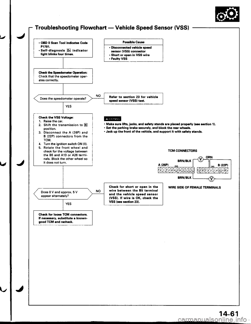
Troubleshooting Flowchart - Vehicle Speed Sensor {VSS)
Pos.ibl. C.u3o
. D|""."-"t"d .r"hl"L 3p*daanaor (VSSI connactol. Short or opan in VSS wira. F.ulty VSS
@. M.k. .ur. 11ft3, l.cl(., .nd ilt ty .l.nds .r. pl.c.d prop€rly (t€a .cction 11.. Srt th. p!.king b..ko rlcur.ly, lnd block thr r..r wh..b.. J.ck up th. t?ont ol ih. yohlcl., lnd .upport it whh rdlty rt.ndr.
WIRE SIDE OF FEMAI.C TERMINALS
. OBD ll Sc.n Tool indlcrt . Cod.Pl791.. s.lt-dl.gno.i. E indicrtorllghi blinkr four tirn.r.
Ch.d( tho Sp..dom.t r Op.r.don:Checkthat the spoedometgr opeFat€s corrsctlv.
R.t.r io ..ctlon 23 lor v.hlcl.!p.!d tlnto. IVSSI t rt.
Ch.ck thr VSS Voh.g.:1. Baise th6 car.2. Shift the transmission to Eposition.
3. Disconn€ct tho A (26P) andB (22P1 conn€ctors from theTCM.4. Turn the ignition switch ON (ll).
5. Rotate the front wheel sndcheck for th6 voltage botws€nthe 95 and A'13 or 426 termi-nals. Block th€ oth6r wheel soit does not turn.
Chack tor ahorl or opan in ihawlra batwaan tha 85 tarmin.land tha vahicla tpaad tanror{VSSI. ll wirc i! OK, ch.ck th.VSSk ot ction 23).
Chack io. loo.c TCM conn.ctors.It nacasaary. rubditut . known-good TCM .nd r.ch.ck.
TCM CONNECTORS
14-61