sensor HONDA INTEGRA 1998 4.G Workshop Manual
[x] Cancel search | Manufacturer: HONDA, Model Year: 1998, Model line: INTEGRA, Model: HONDA INTEGRA 1998 4.GPages: 1681, PDF Size: 54.22 MB
Page 487 of 1681
Electrical Troubleshootin g
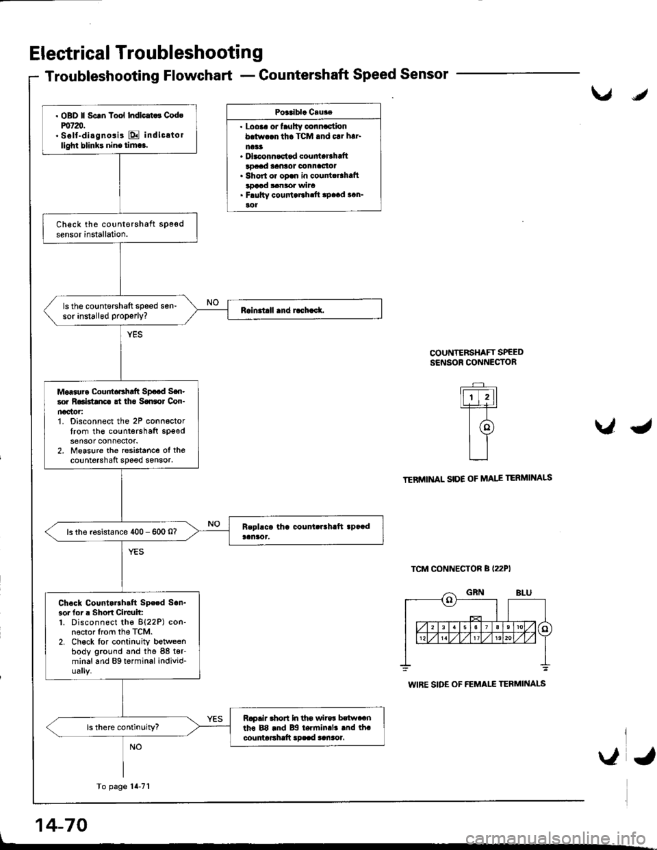
Troubleshooting Flowchart - Countershaft Speed Sensor
Posalbla Cruae
. Loora or faulty connactionb.tw.$ tho TCM and 61 h!1.
na33. Dbconnactad couniaBhaftlocad lantot oonnac{ot. Shorl or opan in counta6hatttDaad $naor wha. F.ultv coufiaEh.ft apaad acn-aol
COUNTERSHAFT SPEEDSENSOR CONNECTOR
\IJ
U\lO
.-_
lfr-trtlL+l-r-T-
t@tl
L__l
TENMINAL SIDE OF MAIE
TCM CONNECTON B (22PI
TERMINALS
L
14-70
WIBE SIDE OF FEMALE TERMINALS
. OBD ll Scrn Tool Indlcat ! Cod.m720.. Self-diagnosis E indicatollighl blinks nine tim6.
ls the countershaft speed sen-sor installed properly?
Moas{ra Cour 6Ghaft Sp€od Sen-60r R6Btanca gt iha SaGol Con-n€c'tor:1. Disconnect the 2P connectortrom the countershafl spgodsensor connectof.2. Measure the resistance ol thecountershaft speed sensor.
ls the rosistance 400 - 600 O?
Check Countorrhcft Spe.d Son-3ol for r Shon Circuit:1. Disconnect the 8{22P) con-nector lrom the TCM.2. Ch€ck lor continuity betweenbody ground and the 88 t€r-minal and Bg terminal individ-ually.
Rapair rhon In th6 wiro! hwaantho E8 rnd Bg te.min.l. .nd th.countaFhaft !D..d aanaol.
To page'14-71
\,a,
Page 488 of 1681
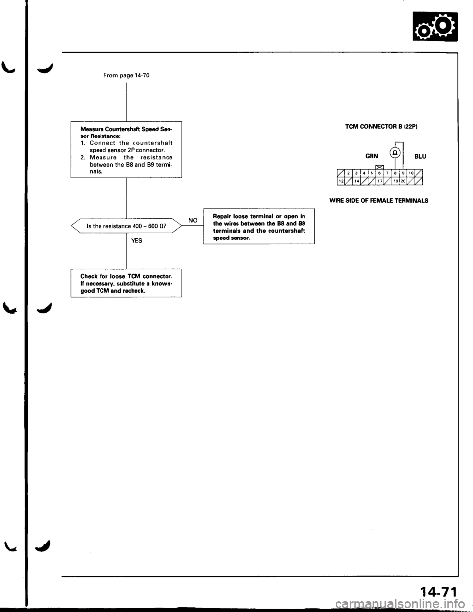
Mgasuro CountoFhaft Spo€d Sen-sor Re3btancg:1. Con nect the countershaftspeed sensor 2P connedor,2. Measure the resistancebetween the 88 and gg termi-nals.
Ropair looto torminsl or opgn inthe wires b.twoon th6 88 .nd 89torminals and tho countor3haftspoad s€nsor.
ls the resistance 400 - 600 0?
Chock for loo3o TCM connodor.lf neceatary, substitute a known.good TCM and rochock.
From page 14-70
TCM CONNECTOR B I22P)
WIRE SIDE OF FEMALE TERMINALS
14-71
Page 489 of 1681
Electrical Troubleshooting
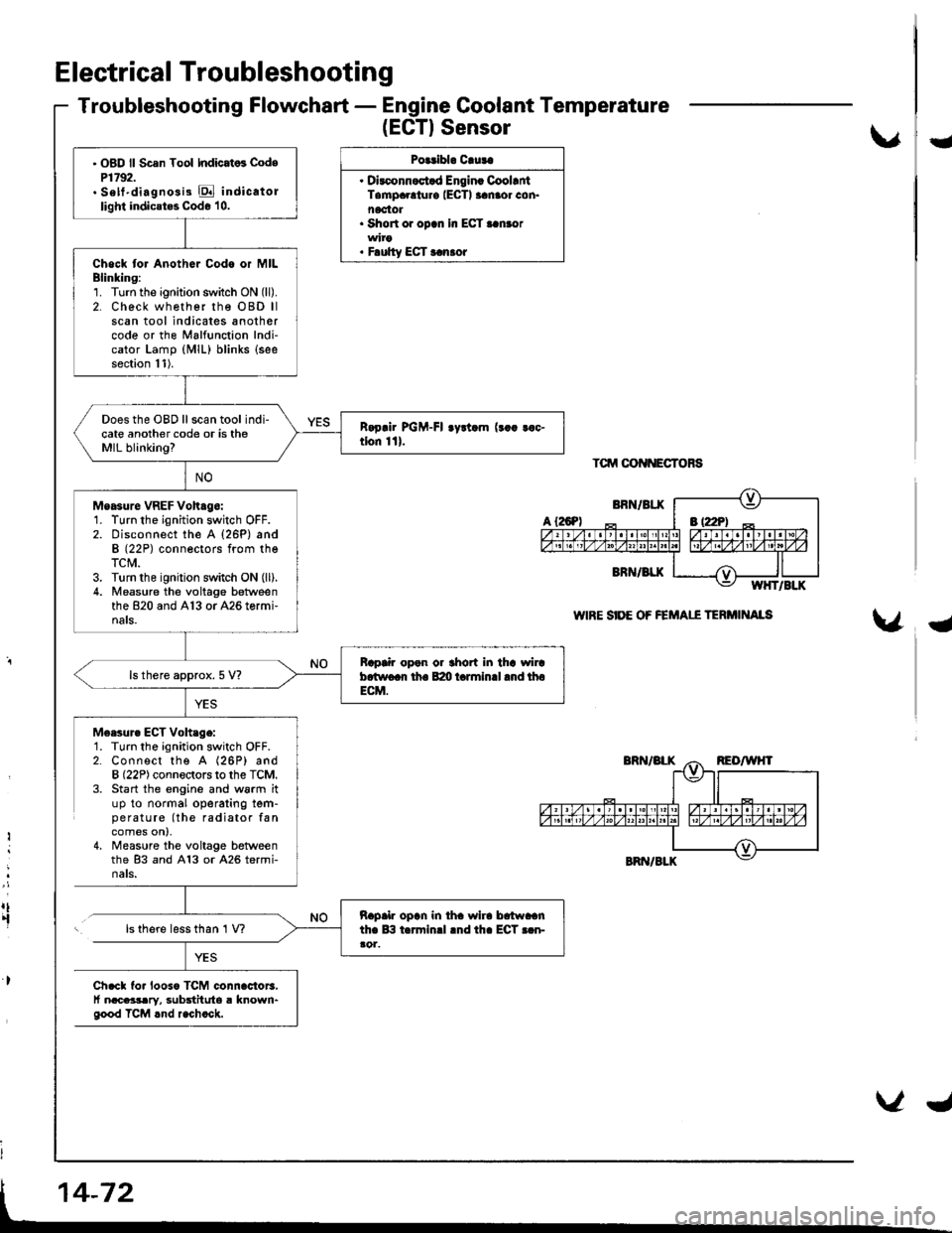
Troubleshooting Flowchart - Engine Coolant Temperature
(EGTISensor
Polribl. Cluta
. Dirconnoct.d Engin. CoollntTampaolur€ IECTI aanaor con.noctot. Short or opcn In ECT..n.or
. F.ulty ECT r.n.or
Tctrrt oot{NEcToRs
WIRE SIDE OF FEMAII TERi'IINAIS
U
{
M6esur. ECT Voh.ge:1. Turn the ignition switch OFF.2. Connect the A (26P) andB (22P) connectors to the TCM.3. Start the engine and w6rm ituP to normal operating tem-pe ratu re (the radiator fancomes on),4, Measure the voltage betweenthe 83 and A13 or A26 termi-nats.
Ii
:
rt.fls there less than 1 V?
Ch.cl fo. looso TCM connac{or3,t nacaasary, substituto a known"good TCM rnd r.chock.
' OBD ll Scsn Tool Indicat6 CodeP1792.. Sett'diagno3i3 E indicatollight indicates Code 10.
Chock tor Anothor Codo or MILBlinking:1. Turn the ignition switch ON (ll).
2. Check wh€ther rhe OBD llscan tool indicates anothercode or the Malfunction Indi-cator Lamp (MlL) blinks (see
section 11).
Does the OBD ll scan tool indi-cate another code or is theMIL blinking?
Moasure VREF Voh.go:1. Turn the ignition switch OFF.2. Disconnect the A {26P) andB (22P) conneotors from theTCM.3. Turn the ignition switch ON (ll).
4. Measu.e the voltage betweenthe 820 and A13 or A26 tormi-nals.
Bap|ir open or thort in tha wircb.two.r th. B:m t.rminll .nd thoECM.
ls there approx. 5 V?
napalr opln in iha wlra brtwaanthe lB t.rminrl lnd th. ECT r.n-ao1.
Page 491 of 1681
Electrical Troubleshooting
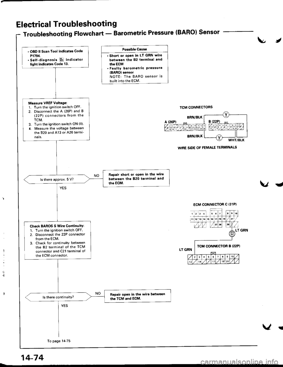
Troubleshooting Flowchart - Barometric Pressure (BARO) Sensor
t\l,
l
'|
. OBD ll Scan Tool lndicatos Code
P1794.. Self-diagnosis El indicator
light indicatos Code 13.
Check BAROS S Wire ContinuitY:1. Turn the ignition switch OFF.
2. Disconnect the 22P connedortrom the ECM.3. Check for continuity betweenthe 82 terminal ot the TCM
connector and C21 terminal of
the ECM connector.
PGsible cau3€
' Short ot oDen in LT GRN wite
betwoen the 82 lcrminal and
ihe ECM. Faulty baromotric PrelsureIBAROI ignsolNOTE: Tho BAFO sensor is
built into the ECM.
VqJ
WIRE SIDE OF FEMALE TERMINALS
Measure VREF Volttge:1. Turn the ignition switch OFF.
2. Disconnect the A (26P) and B(22 P) connectors from the
TCM.3. Turn the ignition switch ON {ll}.
4. Measure the voltage between
the 820 and 413 or 426 termi-
nals,
Repair shon or oPen in the wite
betwcon the 820 tsrminal and
tho EcM.ls there approx.5 V?
Repair open in the wiro betwoon
the TcM and ECM.ls there continuity?
To page 14-75
14-74
V!
Page 495 of 1681
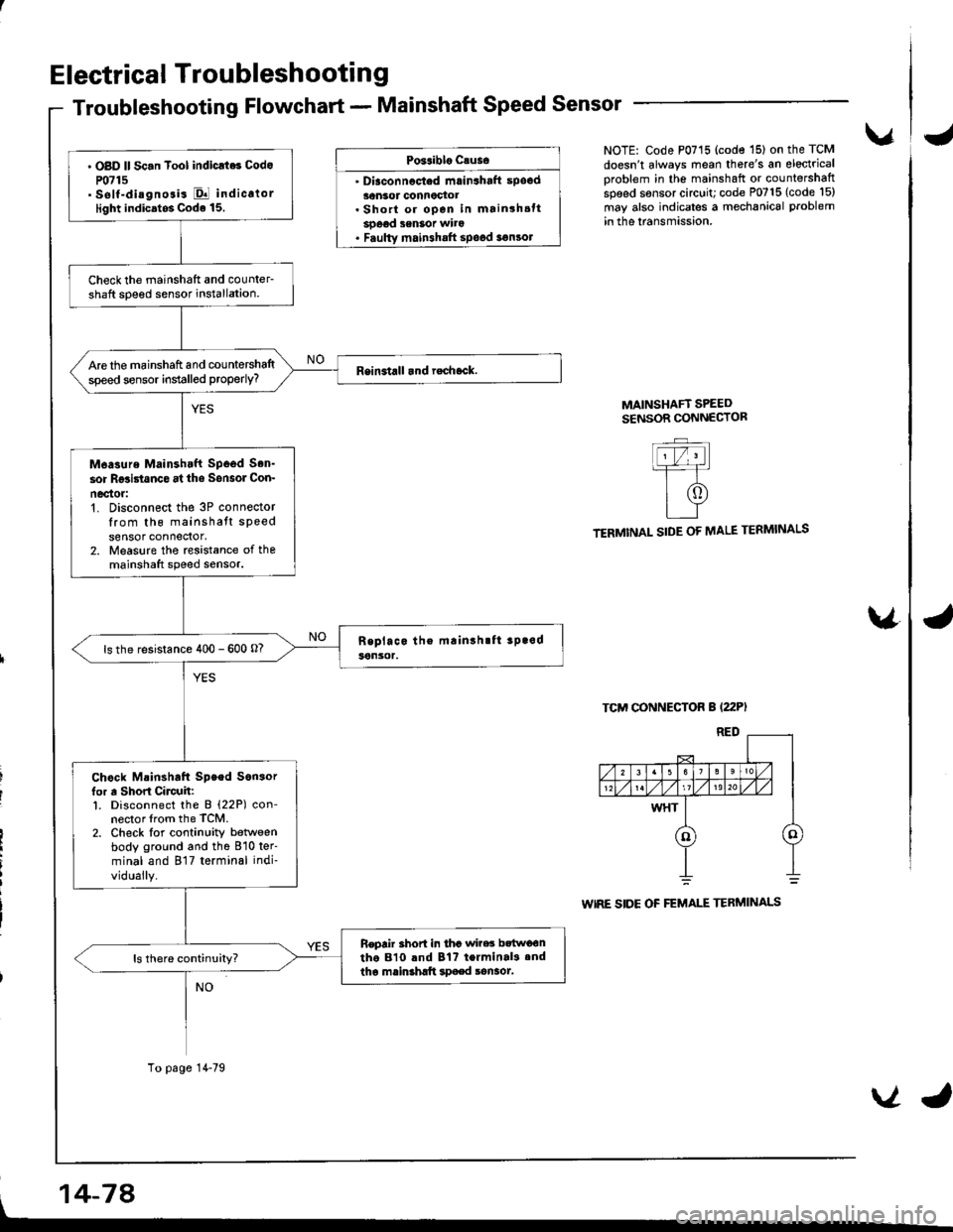
Electrical Troubleshootin g
Troubleshooting Flowchart - Mainshaft Speed Sensor
Po3aiblo causo
' Diaconnocted mrin3haft spocd30nsor connoctot. Short or open in mainshsttsoeod senSot wito. Faulty main3halt spood 3€n3ol
vNOTE: Code P0715 (code '15) on the TCM
doesn't always mean there's an electrical
oroblem in the mainshaft or countershaftspeed sensor circuit; code P0715 (code l5)
may also indicates a mechanical problem
in the lransmission.
MAINSHAFT SPEEDSENSOR CONNECTOR
TERMINAL SIDE OF MALE TERMINALS
TCM CONNECTOR B (22P)
WIRE SIDE OF FEMALE TERMINALS
\4
' OBD ll Sc.n Tool indicrt6 Codo
P0715' self-diagnosis El indicalorlight indicatos Code 15.
Check the mainshatt and counler-shaft soeed sensor installation.
Are the mainshaft and countershaltspeed sensor installed properly?
M6asure Mainshtft Spood Son'
sor Rgsi5tanco at ths Sonsol Con-
nec'tor:'t. Disconnect the 3P connectorIrom th6 mainshatt speedsensor connedor,2. Measure the rcsistance of themainshaft speed sensor.
ls the resistance 400 - 600 o?
Chock Mainshaft Speed Son3orfor a Short Circuh:l. Disconnect the B (22P) con-nector lrom the TCM.2. Check lor continuity betlveenbody ground and the 810 ter'
minal and 817 terminal indi-
vidually.
Repair 3hort in tha wi?es bttwo€ntho 810 lnd Bt? terminal3.ndtha mainshltt spaed sonaot.
To page 14-79
, 14-74
VJ
Page 496 of 1681
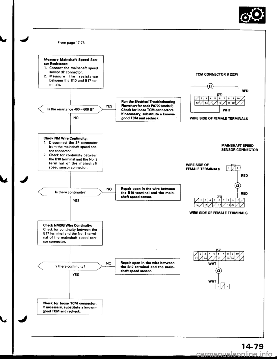
From page 17-78
Mo!3urc Mrinahaft Spced Son-sor Rosistrnco:1. Connoct the mainshaft speedsensor 3P conn6ctor.2. Measure the resista nc6between the 810 and 817 ter-minals.
Run th. ELcticrl TlouH..hootingHolrrdrart lor cod. m720 (codo 91.Chock lor looaa TCM connactor3.lf nacllg!ry, $badtuta a known-good TCM rnd i.ch.ck.
ls the resistance 400 - 600 0?
Ch.ck NM Wiro Continuity:1, Disconnect the 3P connector{rom the mainshaft sp6ed sen-sor connector,2. Check for continujty betweenthe B10 terminalandthe No. 3terminal of the mainshattspeed sensor connector.
R€paia opon in tha wir. bctwoanth. 810 t.rmin.l lnd th. m.in-3hrft apaad sanaor.
Check NMSG Wl.e Continuity:Check for continuity b€twoen theB'17 terminal and the No. 1 t6rmi,nal oI the mainshaft speed s6n-sor connector.
Rapair opan in thc wiia batwacnth6 Bl7 t.rmin.l .nd th. m.ln.3hdt rDaad aansor,
Chock lor loo3e TCM connactor.It n.cGslry, $bititutc ! known-good TCM lnd r.chock.
TCM CONNECTOR B I22PI
WIBE SIDE OF FEMALE TERMINALS
WIRE SID€ OF FEMAI"E TERMINALS
MAINSHAFT SPEEOSENSOR CONNECTOR
14-79
Page 506 of 1681
uJ
14-89
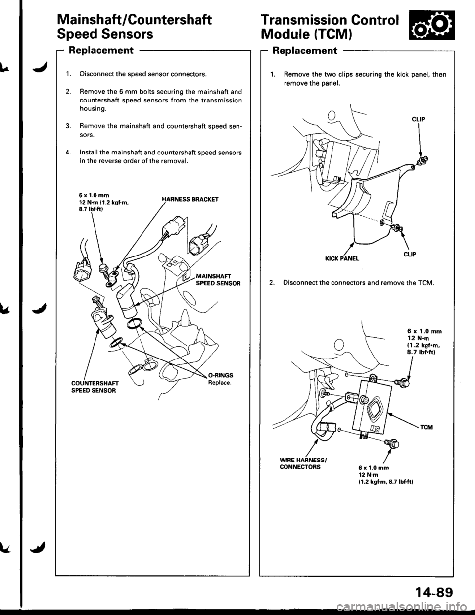
Ma i nshaft/Cou ntershaft
Speed Sensors
Replacement
l.
2.
Disconnect the speed sensor connectors.
Remove the 6 mm bolts securing the mainshaft and
countershaft speed sensors from the transmission
housing.
Remove the mainshaft and countershaft speed sen-
sors.
Installthe mainshaft and countershaft speed sensors
in the reverse order of the removal.
6x1.0mm12 N.rn 11.2 kgtm,8.7 tbttrt
Transmission Control
Module (TCM)
Replacement
1. Remove the two clips socuring the kick panel, then
remove the oanel.
2, Disconnect the connectors and remove the TCM.
6 x 1.0 rnm12 N.m{1,2 kgt.m,8.7 tbt.ft)
CONNECTORS
Page 508 of 1681
L
\a
\."tl
14-91
J
al
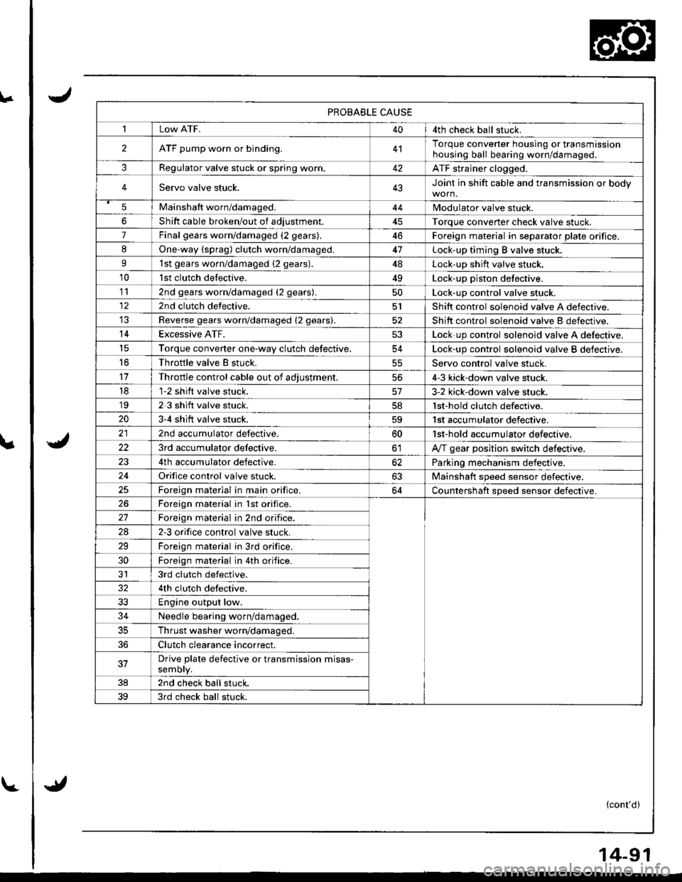
PROBABLE CAUSE
1Low ATF.404th check ball stuck.
2ATF pump worn or binding.4'lTorque converter housing or transmissionhousing ball bearing worn/damageo.
3Regulator valve stuck or spring worr..42ATF strainer clogged.
4Servo valve stuck.43Joint in shift cable and transmission or body
5Mainshaft worn/damaged.44Modulator valve stuck.
6Shift cable broken/out of adiustment45Torque converter check valve stuck.
7Final gears worn/damaged (2 gears).46Foreign material in separator plate orifice.
8One.way {sprag) clutch worn/damaged.47Lock-up timing B valve stuck.
91st gears worn/damaged {2 gears).4ALock-up shift valve stuck.
10lst clutch defective.49Lock-up piston defective.
112nd gears worn/damaged (2 gears).50Lock-up control valve stuck.
122nd clutch defective.5lShift control solenoid valve A defective.
Reverse gears worn/damaged (2 gears).52Shift control solenoid valve B defectrve.
14Excessive ATF.53Lock up control solenoid valve A defective,'t5Torque converter one-wav clutch defective.54Lock-up control solenoid valve B defective.
16Throttle valve B stuck.55Servo control valve stuck.
11Throttle control cable out of adiustment.564-3 kick-down valve stuck.
181-2 shift valve stuck.3-2 kick-down valve stuck.'192 3 shift valve stuck.lst-hold clutch defective.
203-4 shift valve stuck.59'| st accumulator defective.
2nd accumulator defective.60'lst-hold accumulator defective,
223rd accumulator delective,olA,rf gear position switch defective,
4th accumulator defective.62Parking mechanism defective.
24Orifice control valve stuck.63Mainshaft speed sensor defective.
Foreign material in main orifice.64Countershaft speed sensor defective.
26Foreign material in lst orifice.
Foreign material in 2nd orifice.
2A2-3 orifice control valve stuck.
29Foreign material in 3rd orifice.
30Foreign material in 4th orifice.
JI3rd clutch defective.
4th clutch defective.
33Engine output low.
34Needle bearing worn/damaged.
35Thrust washer worn/damaged.
36Clutch clearance incorrect.
37Drive plate defective or transmission misas-semory.
382nd check ball stuck.
393rd check ball stuck.
(cont'd)
Page 511 of 1681
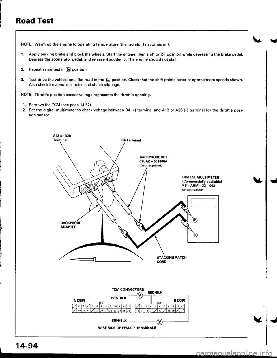
Road Test
NOTE: Warm up the engine to operating temperature (the radiator fan comes on).
1. Apply parking brake and block the wheels. Start the engine, then shift to @ position while depressing the brake pedal-
Depress the accelerator pedal, and release it suddenly. The engine should not stall.
2. Repeat same test in E position.
3. Test drive the vehicle on a flat road in the @ position. Check that the shift points occur at approximate speeds shown.
Also check for abnormal noise and clutch slippage.
NOTE: Throttle position sensor voltage represents the throttle opening.
-1. Remove the TCM (see page 14-52).-2. Set the digital multimeter to check voltage between 84 (+) terminal and A13 or A26 (-) terminal for the throttle posi-
tion sensor.
84 Terminal
DIGITAL MULTIMETER(Commercially availablelKS - AHM -32 - 003oa oquivalent
, 14-94
TCM CONNECTORS
WIRE SIDE OF FEMALE TERMINALS
i
J
Page 512 of 1681
V
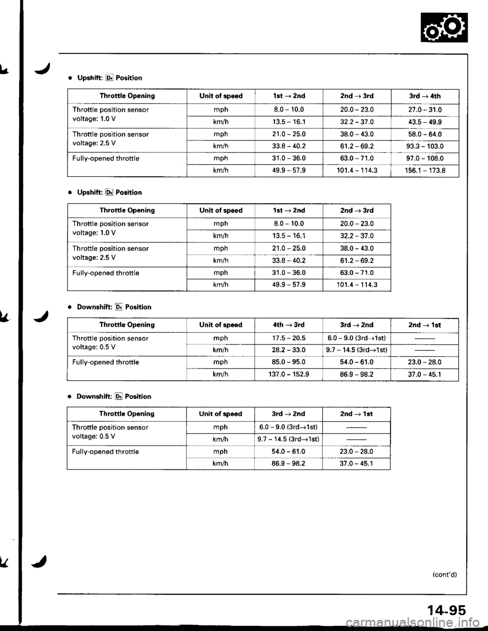
. Upshift: E Position
. Upshift: [d Po3ition
o Downshift: E Position
. Downshift E Position
Throttle OpeningUnit of speadlst + 2nd2nd r 3rd3rd + 4th
Throttle position sensor
voltage: 1.0 V
mpn8.0 - 10.020.0 - 23.027.0 - 31.0
km/h13.5 - 16.132.2 - 31 .043.5 - 49.9
Throttle position sensor
voltage: 2.5 V
mpn21.0 - 25.O38.0 - 43.058.0 - 64.0
km/h33.8 - 40.261 .2 - 69.293.3 - 103.0
Fully-opened throttlemph31.0 - 36.063.0 - 71.097.0 - 108_0
km/h49.9 - 57.9101.4 - 114.3156.1 - 173.8
Throftle OpeningUnit of speedlst -, 2nd2nd -r 3rd
Throttle position sensor
voltage; 1.0 V
mpn8.0 - 10.020.0 - 23.0
km/hI J.C - tO. I32.2 - 37.O
Throttle position sensor
voltage: 2.5 V
mph21.0 - 25.O38.0 - 43.0
km/h33.8 - 40.261.2 - 69.2
Fully-opened throttlemph31.0 - 36.063.0 - 71.0
km/h49.9 - 57.9101.4 - 114.3
Throttle OpeningUnit ol spceditth -+ 3.d3rd r znd2nd r lst
Throttle position sensor
voltage: 0.5 V
mpn17.5 - 20.56.0 - 9.0 (3rdr1st)
km/h24.2 - 33.09.7 - 14.5 (3rd-r1stl
Fully-opened throttlemph85.0 - 95.054.0 - 61.023.0 - 24.0
km/h137.0 - 1s2.986.9 - 98.237.0 - 45.1
Throttle OpeningUnit of speed3rd J zndznd + 13t
Throttle position sensor
voltage: 0.5 V
mpn6.0 -9.0 (3rd-r1st)
km/h9.7 - 14.5 (3rd-+1st)
Fully-opened throttlempn54.0 - 61.023.0 - 28.0
km/h86.9 - 98.237.0 - 45.1
14-95