HONDA INTEGRA 1998 4.G Workshop Manual
Manufacturer: HONDA, Model Year: 1998, Model line: INTEGRA, Model: HONDA INTEGRA 1998 4.GPages: 1681, PDF Size: 54.22 MB
Page 1051 of 1681
J
Glutch Overhaul
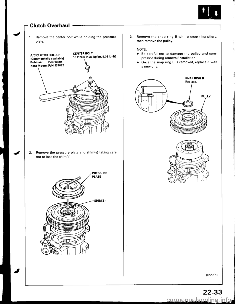
1. Remove the center bolt while holding the pressure
plate,
A/C CLUTCH HOLDER
lCommorcially available)Robinair: P/N 1020,1
Kent-Moor6: P/N J37872
2.
CENTER BOLT13.2 N.m {1.35 kgf m,9 76lbtft)
IRemove the pressure plate and shim(s) taking
not to lose the shim(s).
sHtM(sl
[4
3. Remove the snap ring B with a snap ring pliers,
then remove the pulley.
NOTE:
o Be careful not to damage the pulley and com-
pressor during removal/installation.
. Once the snap ring B is removed, replace it with
a new one.
(cont'd)
I
/ T-\vr= ...--.-
-ffitll---.\lr l,
\-l I .v
22-33
Page 1052 of 1681
Compressor
a
a
Clutch Overhaul (cont'dl
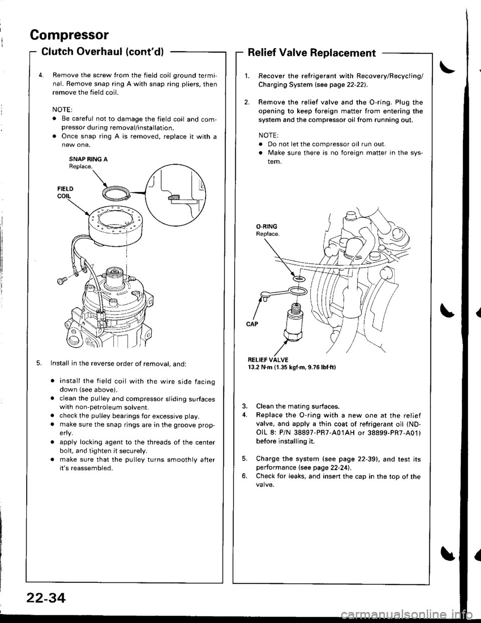
Remove the screw from the field coil ground termi,
nal. Remove snap ring A with snap ring pliers, then
remove the field coil.
. Be careful not to damage the field coil and com-presso. during removal/installation.
. Once snap ring A is removed, replace it with a
SNAP RING AReplace.
5. Install in the reverse order of removal, andl
install the field coil with the wire side facing
down (see above).
clean the pulley and compressor sliding surfaceswith non-petroleum solvent.
check the pulley bearings for excessive play.
make sure the snap rings are in the groove prop-
efly.
apply locking agent to the threads of the center
bolt, and tighten it securely.
make sure that the pulley turns smoothly after
it's reassembled.
Relief Valve Replacement
Recover the refrigerant with Recovery/Recycling/
Charging System lsee page 22-221.
Remove the relief valve and the O-ring. Plug the
opening to keep foreign matter from entering the
system and the compressor oil from running out,
NOTE:
. Do not let the compressor oil run out.
. Make sure there is no foreign matter in the sys-
tem.
RELIEF VALVE13.2 N.m (1.35 kgf.m,9.76lbtft)
3. Clean the mating surfaces.
4. Replace the O-ring with a new one at the relief
valve, and apply a thin coat of refrigerant oil (ND-
OIL 8: P/N 38897-PR7-A01AH or 38899-PR7-A01)
before installing it.
5. Charge the system (see page 22-39), and test itsperformance (see page 22-241.
6. Check for leaks, and insert the cap in the top of the
FIELD
t\I lu
B _t_:---\-lr
\,/
22-34
Page 1053 of 1681
J
A/G Compressor Belt
Replacement
Automatic Transmission Type
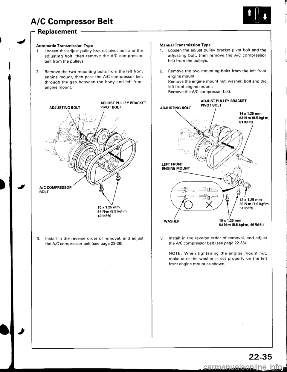
1. Loosen the adjust pulley bracket pivot bolt and the
adjusting bolt. then remove the A/C compressor
belt from the Dullevs.
2. Remove the two mounting bolts from the left front
engine mount, then pass the A,/C compressor belt
through the gap between the body and left front
engrne mount.
ADJUSTING BOLT
ADJUST PULLEY BRACKETPIVOT BOLT
'10 x 1.25 mm54 N.m {5.5 kgl m,
40 rbtftl
Install in the reverse order of removal, and
the Ay'C compressor belt (see page 22 36).
aoJUsI
ll
Manual Transmission Type
1. Loosen the adjust pulley bracket pivot bolt and the
adjusting bolt, then remove the A/C compressor
belt from the pulleys.
2. Remove the two mounting bolts from the left front
engrne mount.
Remove the engine mount nut, washer, bolt and the
left front engine mount.
Remove the !i/C compressor belt.
ADJUST PULLEY BRACKETPIVOT BOLTAOJUSTING BOLT
14 x 1.25 mm83 N.m {8.5 kgl.m,61 rbf.ft)
LEFT FRONTENGINE MOUNT
wasHEB lu x l.z5 mm54 N.m (5.5 kgl m, 40lbtft)
3. Instali in the reverse order of removal, and adjust
the A,/C compressor belt (see page 22 36i.
NOTE: When tightening the engine mount nut,
make sure the washer is set properly on the left
front engine mount as shown.
T':
22-35
Page 1054 of 1681
A/C Compressor Belt
Adiustment
Dellection Method
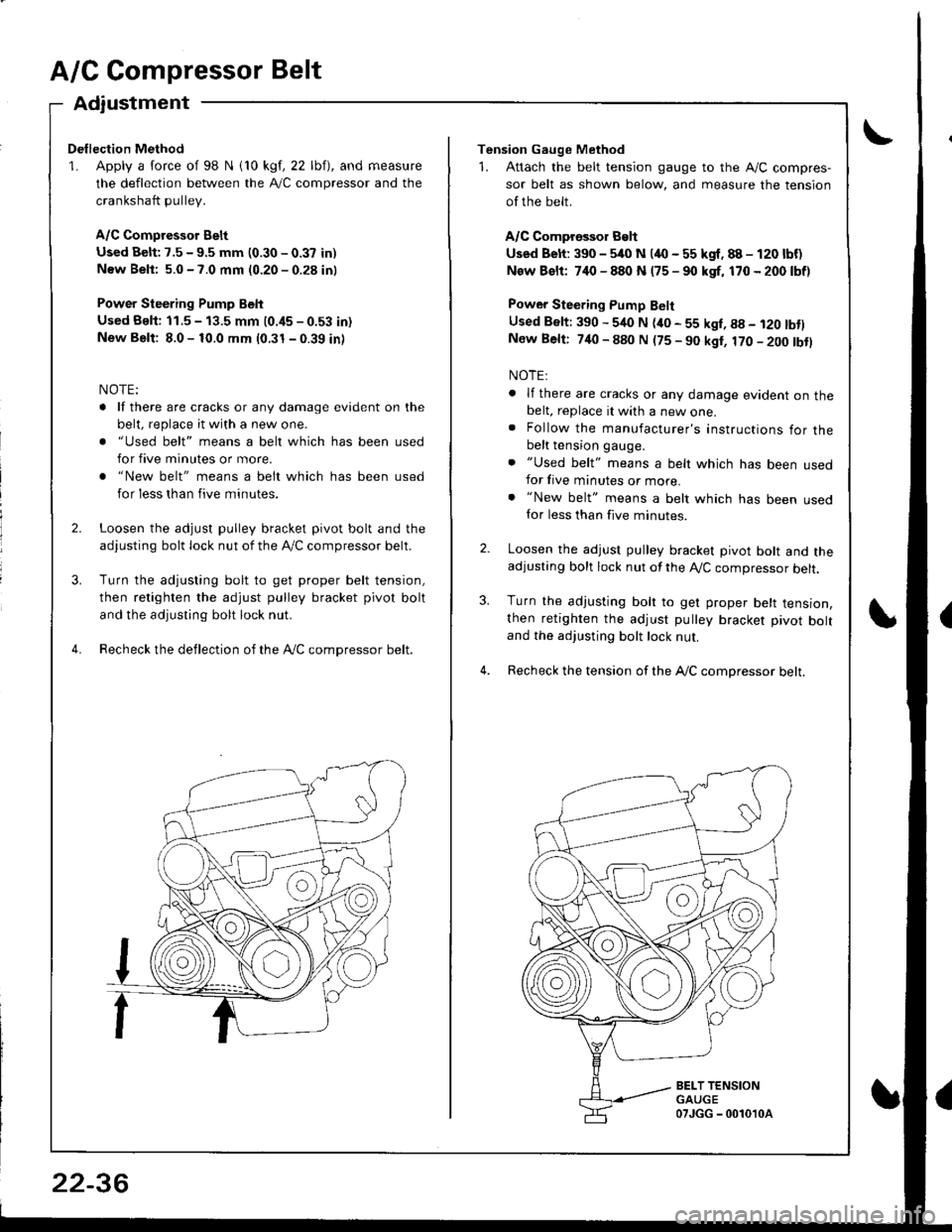
1. Apply a force of 98 N i10 kgf, 22 lbf), and measure
the deflection between the A,/C compressor and the
crankshaft pullev.
A/C Compressor Belt
Used Belt: 7.5 - 9.5 mm (0.30 - 0.37 in)
New Beli: 5.0 - 7.0 mm (0.20 - 0.28 in)
Power Steering Pump Belt
Used Bslt: 11.5 - 13.5 mm (0.i15 - 0.53 in)
New Belt: 8.0 - 10.0 mm (0.31 - 0.39 in)
NOTE:
. lf there are cracks or any damage evident on the
belt, replace it with a new one.
. "Used belt" means a belt which has been used
for five minutes or more.
. "New belt" means a belt which has been used
for less than five minutes.
Loosen the adjust pulley bracket pivot bolt and the
adjusting bolt lock nut of the lVC compressor belt.
Turn the adjusting bolt to get proper belt tension,
then retighten the adjust pulley bracket pivot bolt
and the adjusting bolt lock nut.
Recheck the deflection of the Ay'C compressor belt.
22-36
Tension Gauge Method
1. Attach the belt tension gauge to the Ay'C compres-
sor belt as shown below, and measure the tension
of the belt.
A/C Comprossor Belt
Used Belt: 390 - 5/rc N (4O - 55 kgf. 88 - 120 lbf)
New Bslt: 7,10 - 880 N (75 - 90 kgf, 170 - 200 lbf)
Power Steering Pump Belt
Used Belt: 390 - 540 N (ito - 55 kgl, g8 - i20 tbtlNew Belt: 740 - 880 N (75 - 90 kgt, 170 - 200 tbtl
NOTE:
. lf there are cracks or any damage evident on thebelt, replace it with a new one.. Follow the manufacturer's instructions for thebelt tension gauge.
. "Used belt" means a belt which has been usedfor five minutes or more.. "New belt" means a belt which has been usedfor less than five minutes.
Loosen the adjust pulley bracket pivot bolt and theadjusting bolt lock nut of the A,/C compressor belt.
Turn the adjusting bolt to get proper belt tension,then retighten the adjust pulley bracket pivot boltand the adjusting bolt lock nut.
Recheck the tension of the A,/C compressor belt.
3.
BELT TENSIONGAUGE07JGG - 0010'l0a
Page 1055 of 1681
Condenser
J
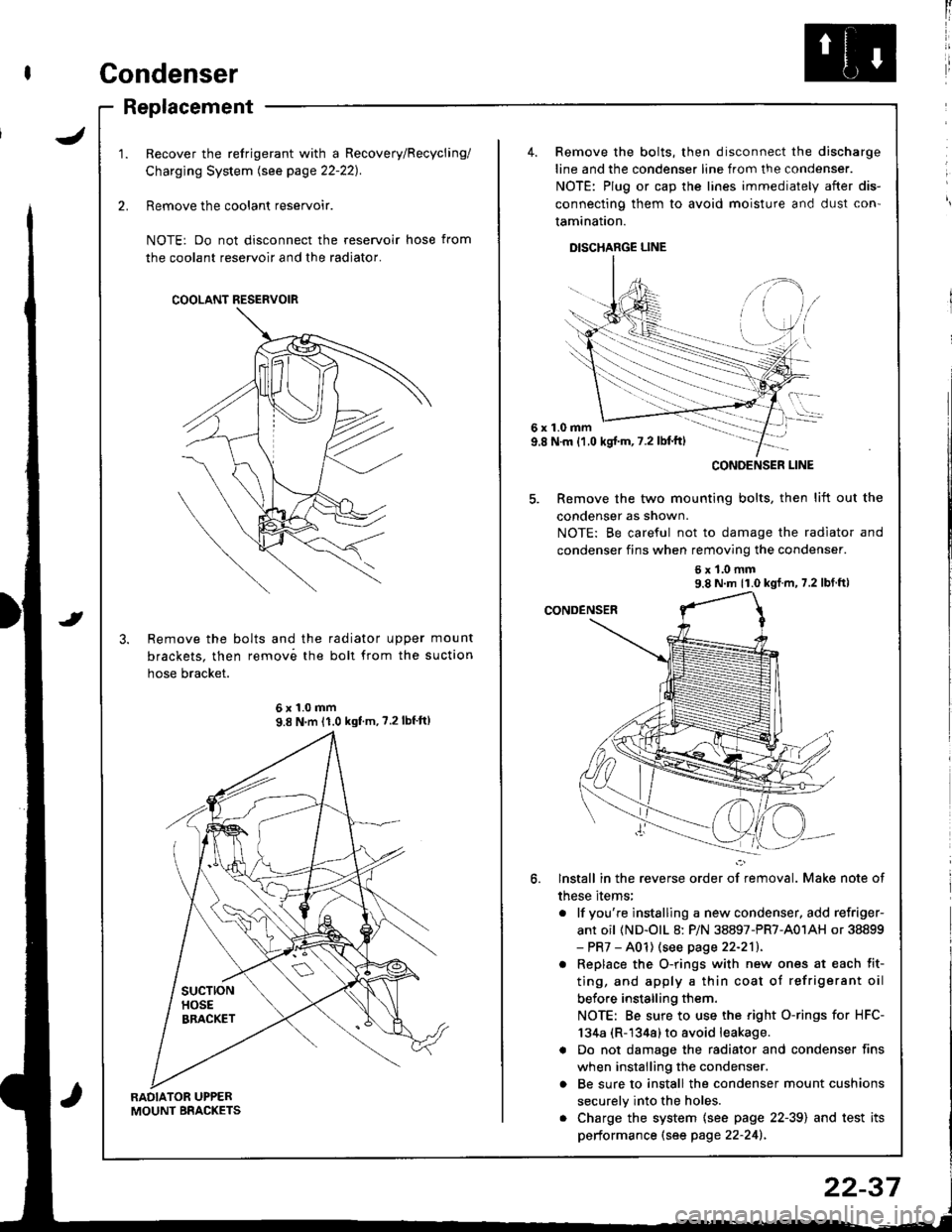
Replacement
RADIATOR UPPERMOUNT BRACKETS
Recover the refrigerant with a Recovery/Recycling/
Charging System lsee page 22-221.
Remove the coolant reservoir.
NOTE: Do not disconnect the reservoir hose from
the coolant reservoir and the radiator.
Remove the bolts and the radiator upper mount
brackets. then remov6 the boll from the suction
hose bracket.
COOLANT RESERVOIR
6x1.0mm9.8 N'm 11.0 kgf'm, ?.2lbf'ft)
4. Remove the bolts, then disconnect the discharge
line and the condenser line from the condenser.
NOTE: Plug or cap the lines immediately after dis-
connecting them to avoid moisture and dust con'
tamination.
DISCHARGE LINE
6x1.0mm9.8 N.m {1.0 kgj'm, 7.2 lbl'ft)
5. Remove the two mounting bolts, then lift out the
condenser as shown.
NOTE: Be careful not to damage the radiator and
condenser fins when removing the condenser.
6x1.0mm9.8 N m 11.0 kgf m, 7.2 lbf ft)
lnstall in the reverse order of removal. Make note of
these items;
. lf you're instslling a new condenser, add refriger-
ant oil (ND-olL 8: P/N 38897-PR7-A01AH or 38899- PR7 - A01) (see page 22-211.
. Replace the O-rings with new ones at each fit-
ting, and apply a thin coat of refrigerant oil
before installing them.
NOTE: Be sure to use the right O-rings for HFC-
134a (R-1344) to avoid leakage.
a Do not damage the radiator and condenser fins
when installing the condenser.
o Be sure to install the condenser mount cushions
securely into the holes.
. Charge the system {see page 22-39) and test its
performance (see page 22-241.
CONOENSER LINE
22-37
Page 1056 of 1681
A/C System Service
Evacuation
Use only service equipment that is U.L.-listed and is cer-
tified to meet the requirements of SAE J2210 to remove
HFC-134a (R-134a) from the air conditioner svstem.
CAUTION: Exposure to air conditioner refrigerant and
lubricant vapor or mist can irtitate eyes, nose and
throat. Avoid breathing the air conditioner refrigerant
and lubricant vapor or mist.
lf accidental system discharge occurs, ventilate work
area before resuming service.
R-134a service equipment or vehicle air conditioner sys-
tems should not be pressure tested or leak tested with
compressed air.
!@@l some mixtures ot air and R-t3ita have
been shown to be combustible at elevated pressures
and can result in fire of explosion causing injury orproperty damage. Never use compressed air to pressure
test R-134a service equipment or vehicle air conditionet
svstems.
Additional health and safety information may be obtained
from the refrigerant and lubricant manufacturers.
When an A"/C Svstem has been ooened to the atmo-
sphere, such as during installation or repair, it must
be evacuated using a R-134a refrigerant Recovery/
Recycling/Charging System. (lf the system has been
open for several days, the receiver/dryer should bereplaced, and the system should be evacuated for
several hours.)
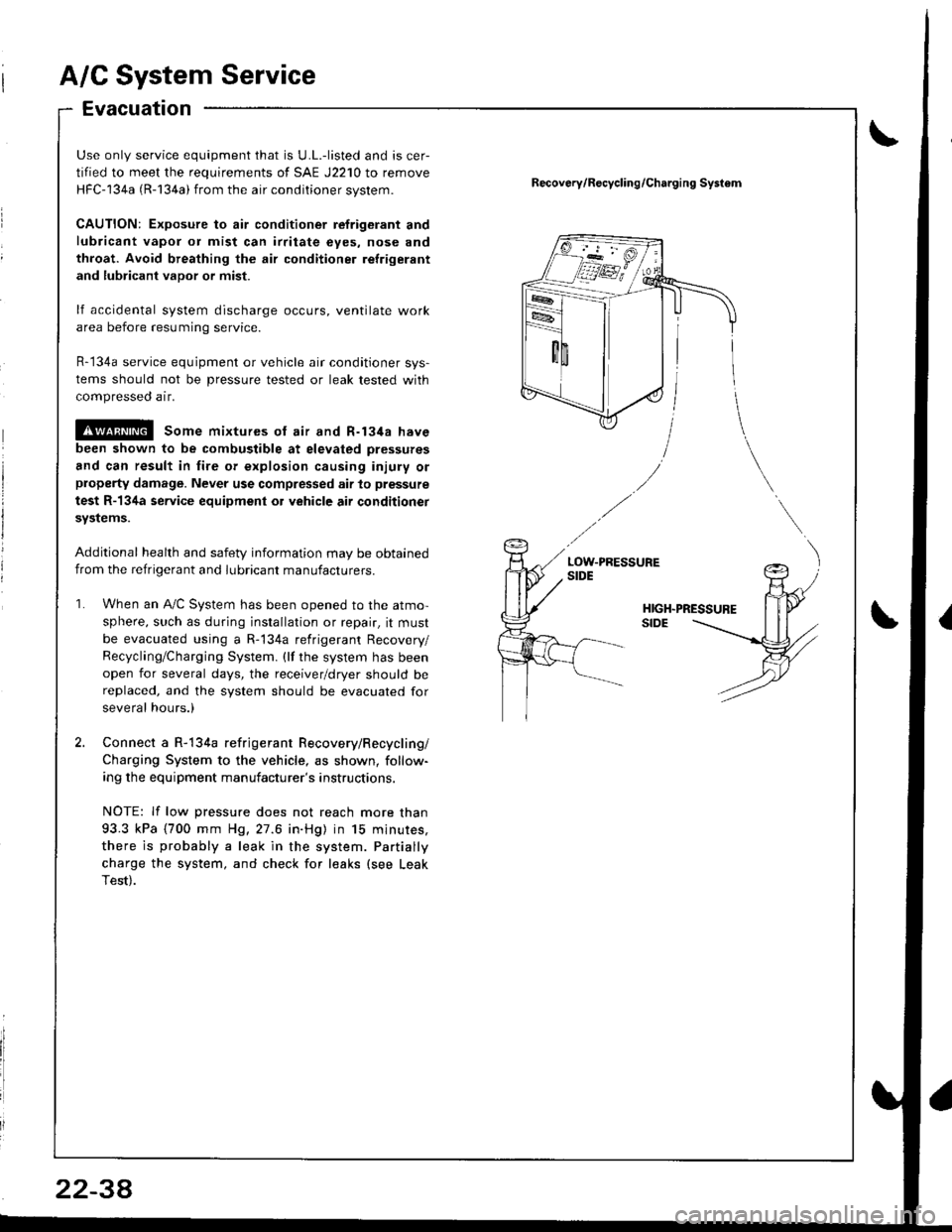
Connect a R-134a refrigerant Recovery/Recycling/
Charging System to the vehicle, as shown, follow-
ing the equipment manufacturer's instructions.
NOTE: lf low pressure does not reach more than
93.3 kPa (700 mm H9,27.6 in.Hg) in 15 minures,
there is probably a leak in the system. Partially
charge the system, and check for leaks (see Leak
Test).
Recov6ry/R€cycling/Charging Systom
2234
Page 1057 of 1681
I
I
ChargingLeak Test
Use only service equipment that is U.L.-listed and is cer-
tified to meet the requirements of SAE J2210 to remove
HFC-134a (R-134a) from the air conditioner system.
CAUTION: Exposure to air conditioner refrig6rant and
lubricant vapol or mist can irritate eyes. nose and
throat. Avoid broating the air conditione. relrigerant
and lubricant vapor o; mist.
lf accidental system discharge occurs, ventilate work
area before resuming service.
R-134a service equipment or vehicle air conditioner sys-
tems should not be pressure tested or leak tested with
compressed air.
@ some mixtures of air and R-1348 have
been shown to be combustible at €levat€d pre3sures
and can rosult in fire or explosion causing iniury or
property damage. Never use compressed air to pressure
test R-134a s€rvics oquipment or vehicle air conditioner
Systems.
Additional health and safety information may be
obtained from the refrigerant and lubricant manufac-
rures.
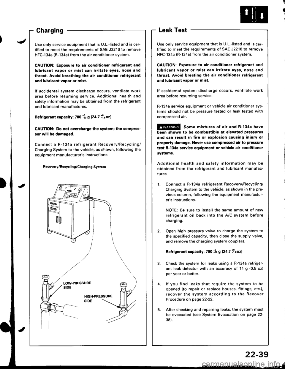
Connect a R-134a refrigerant Recovery/Recycling/
Charging System to the vehicle, as shown in the pre-
vious column, following the equipment manufactur-
er's instructions.
NOTE: Be sure to install the same amount of new
refrigerant oil back into the A/C system before
charging.
Open high pressure valve to charge the system to
the specified capacity, then close the supply valve,
and remove the charging system couplers.
R€frigerani capacity: 700 1o g 124.7 llroz)
Check the system for leaks using a R-134a refriger-
ant leak detector with an accuracy of 14 g (0.5 oz)
per year or better.
lf you find leaks that require the system to be
opened (to repair or replace houses. fittings, etc.),
recover the system according to the Recover
Procedure on page 22-22.
After checking and repairing leaks, the system must
be evacuated (see System Evacuation on page 22-
38).
JUse only service equipment that is U.L.-listed and is cer-
tified to meet the requirements of SAE J2210 to remove
HFC-134a (R-134a) from the air conditioner system.
CAUTION: Exposure to air conditioner r€frigsrant and
lubricant vapol or mist can irritate eyos, nose and
throat. Avoid broathing the air conditioner reftigerant
and lubricant vapor or mist.
lf accidental system discharge occurs, ventilate work
area before resuming service. Additional health and
safety information may be obtained from the refrigerant
and lubricant manufactures.
Retrigerant capscity: 700 % g (2,[.7 i.sozl
CAUTION: Do nol overcharge tho sy3tem; the compres-
sor will b6 damaged.
Connect a R-134a refrigerant Recovery/Recycling/
Charging System to the vehicle, as shown. tollowing the
equipment manufacturer's instructions.
n6covery/Rocycling/Charging Svslem
LOW-PRESSURESIDE
22-39
Page 1058 of 1681
J
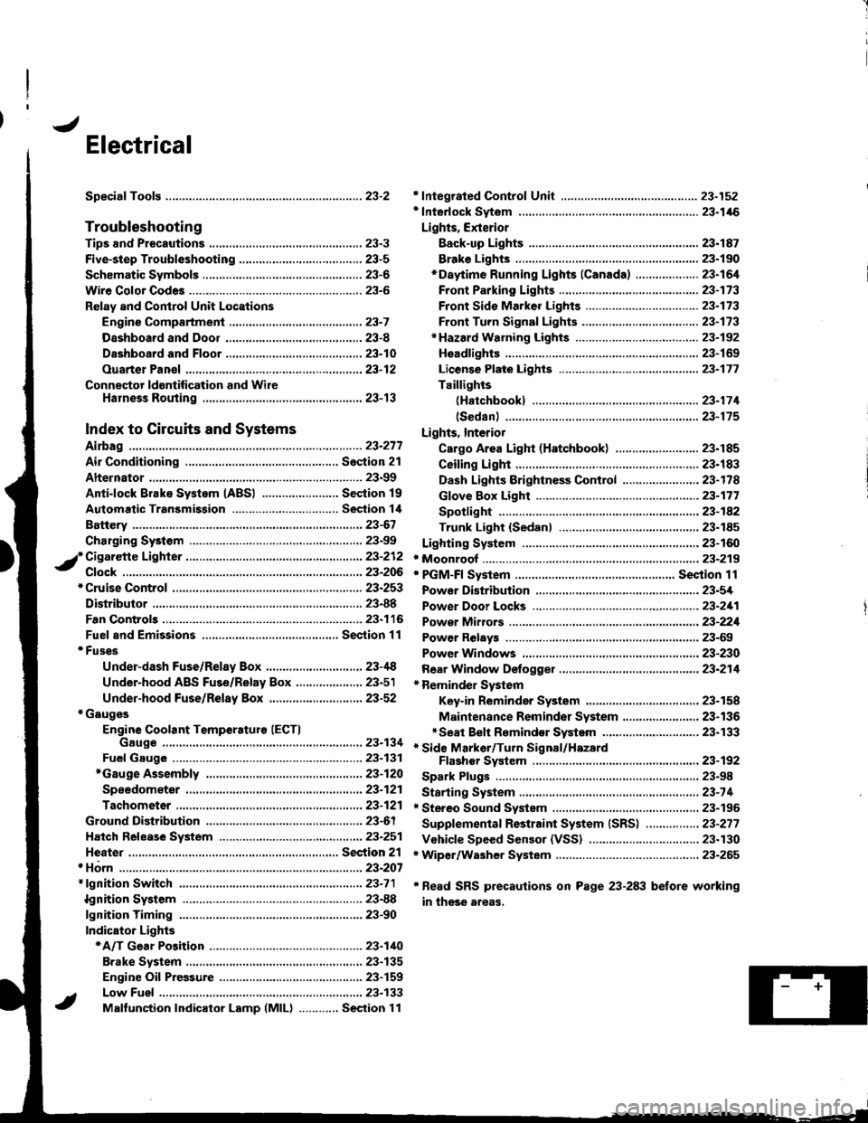
Electrical
Speciaf Toofs ..........................23-2
Troubleshooting
Tips 8nd Precautions .......................,..,.,.,.,.,......,..., 23-3
Five-step Troubleshooting ............,......,.,.,...,..,....., 23-5
Schsmatic Svmbols ...............23-6
Wire Color Code3 .. ................. 23-6
Relay and Control Unit Locations
Engine Compartment ......,.,.................,.,.,.,.,.,,,, 23-7
Dashboard and Door .........,...........,.....,.,....,.,.... 23-8
Dashboard and Floor ......................................... 23-10
Ouarter Pan€f .,,.,...,.,..,...,,,23-12
Connector ldontification and WireHarness Routing ......,.,......23-'13
Index to Circuits and Systems
Airbag
* Integrated Control Unit .....,.,.,.....23-152* Interlock Sytem .,...,.,...........,. 23.146
Lights, Exterior
Eack-up LighB ..................23.187
Brake Ligh$ ......................23-190*Daytime Running Lights (Canada) ................... 23"164
Front Parking Lights .......................................... 23-173
Front Side Marker Lights .................................. 23-173
Front Turn Signal Lights ..................-.......,...,.,. 23-173* Hazard Warning Lights ....................,........,....... 23-192
Headlights.....23-169
23-253 powerDistribution..................... 23-5/r
Air Conditioning.....,....... Soction 21
Alternator ..........,................... 23.99
iCigarette Lighter .........23-212
*Cruise Control
Distributor
'.'.,.'.'.,.'...,,,,.,''.'.,.',.'''.' 23.277
.............................. 23.88
................... 23-90lgnition Timing ......
Indicator Lights
Key-in Reminder System
Maintenance Reminder System*Seat Belt R€mindor System .,...........................* Side Marker/Turn Signal/HazardFlashcr Svstem .................23-192
Spark Plugs ............................23-98
Starting System .....................23-74* Stereo Sound System ...,......,..........,...,......,.,.,.,..,., 23-196
Supplemental Restraint System (SRS) ................ 23-277
Vshicle Speed Sensor (VSS) ................................. 23.130r Wiper/Washer System .........................................., 23-265
*Read SRS precautions on Psge 23-283 before working
in those areas,
23-154
23.136
23"133
Page 1059 of 1681
![HONDA INTEGRA 1998 4.G Workshop Manual SpecialTools
\
Ref. No. J Tool NumbelDescliptionOty Page Reference
o-
o
\9-]
@
o
E
o
@
o
@-
07HAz - SG00400
07JAA - 001000c
07JGG - 001010A
OTLAJ _ PT3O2OA
07NAC - SR20100
07PAZ - 0010100
07sAz - TB4 HONDA INTEGRA 1998 4.G Workshop Manual SpecialTools
\
Ref. No. J Tool NumbelDescliptionOty Page Reference
o-
o
\9-]
@
o
E
o
@
o
@-
07HAz - SG00400
07JAA - 001000c
07JGG - 001010A
OTLAJ _ PT3O2OA
07NAC - SR20100
07PAZ - 0010100
07sAz - TB4](/img/13/6069/w960_6069-1058.png)
SpecialTools
\
Ref. No. J Tool NumbelDescliptionOty Page Reference
o-
o
\9-]
@
o
E'
o
@
o
@-
07HAz - SG00400
07JAA - 001000c
07JGG - 001010A
OTLAJ _ PT3O2OA
07NAC - SR20100
07PAZ - 0010100
07sAz - TB4011A
07TAZ - SZ5011A
07r Az - s250200
07TM - 001020A
Deployment Tool
Antenna Nut Wrench
Belt Tension Gauge
Test Harness
Fuel Sender Wrench
SCS Service Connector
SRS Inflator Simulator
SRS Simulator Lead C
SCS Service Connector (2 o)
Backprobe Adapter, l7 mm
1,|
1
1
1
1
1'l
1
2
23-320
23-203
23-1't5
23-124
23-90,288
23-301
23-30'l
23-301
23-287
*r: lncluded in SRS Tool Set 07MAz - SM5000B*,: Use with the staking patch cords from T/N 07SM 0010004, Backprobe Set.
o
o
@@
23-2
Page 1060 of 1681
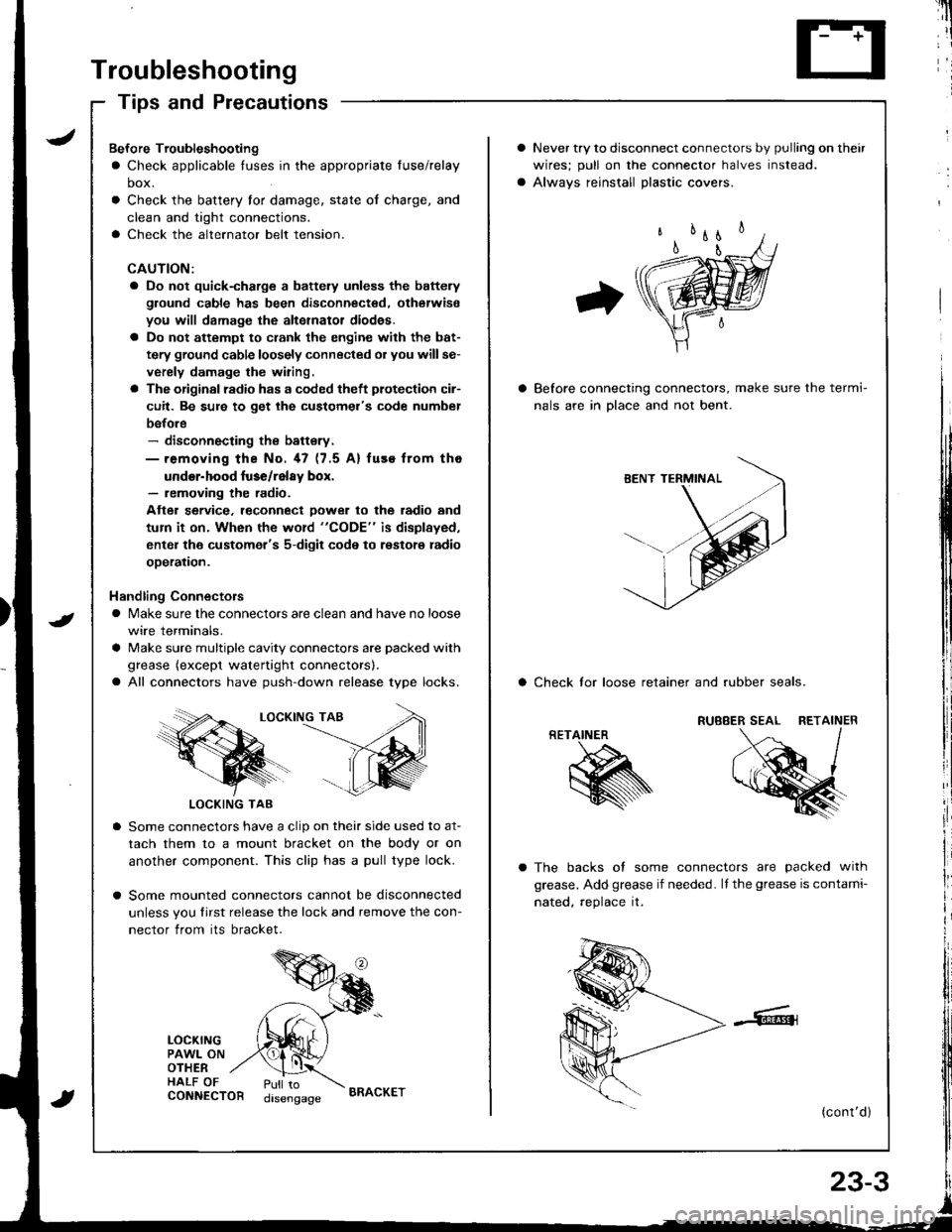
Troubleshooting
Tips and Precautions
Never try to disconnect connectors by pulling on their
wires; pull on lhe connector halves instead.
Alwavs reinstall Dlastic covers.
Before connecting connectors, make sure the termi-
nals are in Dlace and not bent.
a Check lor loose retainer and rubber seals.
The backs of some connectors are packed with
grease. Add grease if needed. lf the grease is contami-
nated, reolace it.
(cont'd )
RETAINER
K
Bef ore Troubleshooting
a Check applicable tuses in the appropriate fuse/relay
box.
Check the battery for damage, state of charge, and
clean and tight connections.
Check the alternator belt tension.
CAUTION:
a Do not quick-charge a battely unless the battery
ground cable has been disconnected. otherwise
you will damage the alternator diod€s.
a Do not attempt to crank the engine with the bat-
tery ground cable loosely connected or you willse-
verely damage the wiring.
a The originsl radio has a coded theft plotection cir-
cuit. Be sure to get the customel's code numbel
before- disconnecting the battsry.- removing the No. 47 (7.5 A) fuse from tho
under-hood luse/relay box.- removing the radio.
Atter service. leconnect Dower to the radio and
tum it on. When the word "CODE" is displayed,
enter the customer's 5-digit code to restore radio
ooeration.
Handling Connectors
a Make sure the connectors are clean and have no loose
wire terminals.
a Make sure multiple cavity connectors are packed with
grease (except watertight connectors).
a All connectors have push-down release type locks.
LOCKING TAB
LOCKING TAB
Some connectors have a clip on their side used to at-
tach them to a mount bracket on the body or on
another component. This clip has a pull type lock.
Some mounted connectors cannot be disconnected
unless you tirst release the lock and remove the con-
nector from its bracket.
LOCKINGPAWL ONOTHERHALF OFCONNECTORPull todisengageBRACKET