HONDA INTEGRA 1998 4.G Workshop Manual
INTEGRA 1998 4.G
HONDA
HONDA
https://www.carmanualsonline.info/img/13/6069/w960_6069-0.png
HONDA INTEGRA 1998 4.G Workshop Manual
Trending: brake, window, ignition, relay, battery, Photo 79, boot
Page 1061 of 1681
Troubleshooting
Tips and Precautions (cont'd)
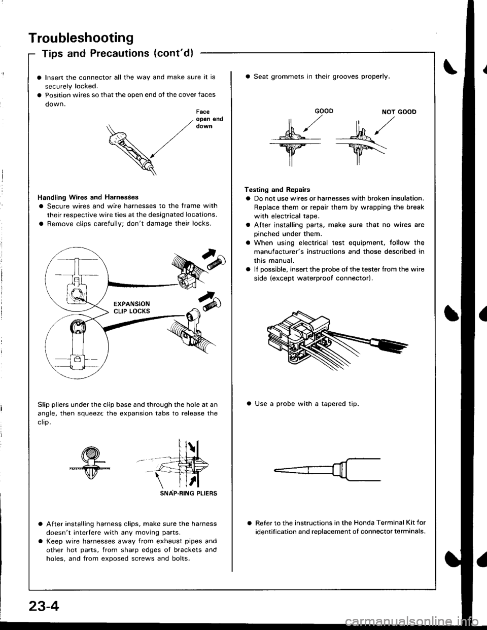
Insert the connector all the way and make sure it is
securely locked.
Position wires so that the open end of the cover faces
down.Faceopen end
V
Handling Wires and Harnesses
I Secure wires and wire harnesses to the frame with
their respective wire ties at the designated locations.
a Remove clips carefully; don't damage their locks.
Slip pliers under the clip base and through the hole at an
angle, then squeez€ the expansion tabs to release the
clro.
sNAP-R|NG PLtERS
After installing harness clips, make sure the harness
doesn't interlere with any moving parts.
Keep wire harnesses away from exhaust pipes and
other hot parts, trom sharp edges ol brackets and
holes, and from exposed screws and bolts.
GOOD NOT GOOD
MA/
lr lr\
Testing and Repairs
a Do not use wires or harnesses with broken insulation.
Replace them or repair them by wrapping the break
with electrical tape.
a Atter installing parts. make sure that no wires are
oinched under them.
a When using electrical test equipment. follow the
manulacturer's instructions and those described in
this manual.
a lI possible, insert the probe of the tester {rom the wire
side {except waterproot connector).
a Seat grommets in their grooves properly.
a Use a probe with a tapered tip.
Reler to the instructions in the Honda Terminal Kit for
identification and replacement oI connector terminals.
23-4
Page 1062 of 1681
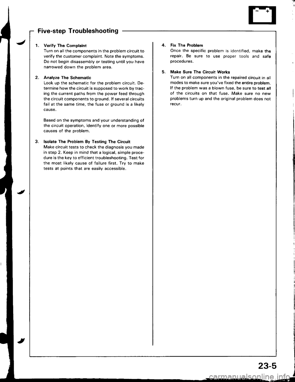
I . Verify The Complaint
Turn on allthe components in the problem circuit to
verify the customer complaint. Note the symptoms.
Do not begin disassembly or testing until you have
narrowed down the problem area.
2- Analyze The Schomatic
Look up the schematic for the problem circuit. De-
termine how the circuit is supposed to work by trac-
ing the current paths from the power feed through
the circuit components to ground. lf several circuits
fail at the same time, the fuse or ground is a likely
Based on the symptoms and your understanding ot
the circuit operation, identity one or more possible
causes of the problem.
3. lsolata The Problem By Testing The Circuit
Make circuit tests to check the diagnosis you made
in step 2. Keep in mind that a logical, simple proce-
dure is the key to efficient troubleshooting. Test for
the most likely cause of failure lirst. Try to make
tests at points that are easilV accessible.
4. Fix The Problem
Once the specific problem is identified, make therepair. Be sure to use proper tools and safep.ocedures.
5. Make Sure The Circuit Workg
Turn on all components in the repaired circuit in allmodes to make sure you've fixed the entire problem.
lf the problem was a blown fuse, be sure to test all
of the circuits on that fuse. Make sure no newproblems turn up and the original problem does not
recuf.
Page 1063 of 1681
Troubleshooting
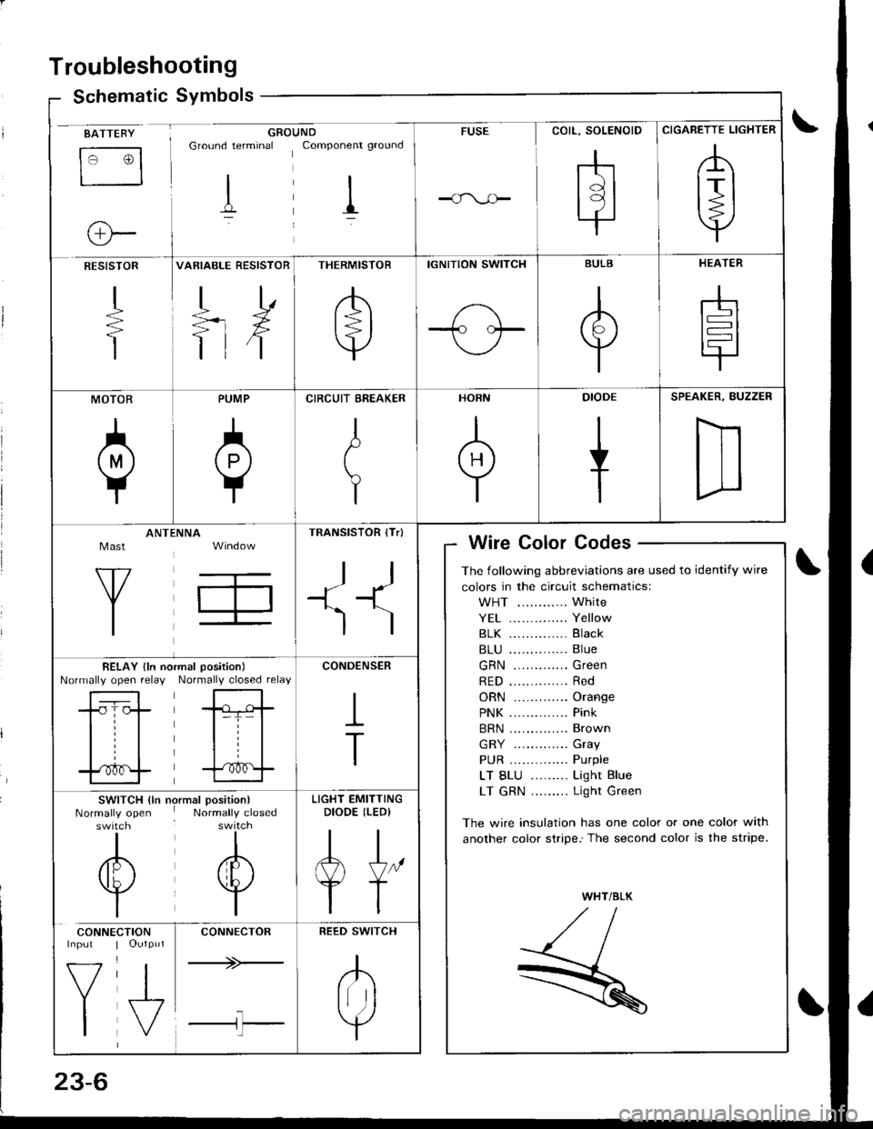
Schematic Symbolsym
BATTEBY
tr3
o-
GROUNDGround terminal Componenr ground
I il
FUSE
COIL, SOLENOID
rhtdl
l9l.|
CIGARETTE LIGHTER
,A
lrl
Y
RESISTOR
+
T
VARIABLE RESISTOR
TD
=rX
ttf
THERMISTOR
/b'
t=l
v
IGNITION SWITCH
1-\-T- l.--
BULB
A
Y
HEATER
-h
t=l
tr
MOTOR
0
PUMP
A
Y
CIRCUIT EREAKER
I
t
Y
HORN
+
DIODE
+
SPEAKER, BUZZER
D
Mast
Y
ANTtiNNA
T,
TRANSISTOR (Tr)
ll
+1^'l
)
Wire Color Codes
The following abbreviations are used to identify wire
colors in the circuit schematics:
WHT ............ White
YE1 .............. Yellow
81K .............. Black
B1U .............. Blue
GRN ............. Green
RED .............. Red
ORN ............. Orange
PNK .............. Pink
BRN .............. Brown
GRY ............. Gray
PUR .............. Purple
LT BLU ......... Light Blue
LT GRN ......... Light Green
The wire insulation has one color or one color with
another color stripe.'The second color is the stripe.
WHT/BLK
,//,aI,//t- /
R
BELAY lln noNormally open relayrmal position)
Normally closed relay
-tr-f,-
l=T= |
til
trf
CONDENSER
I
T
SWITCH {ln nrNormally openswitch
I
/6\
v
I
)rmal position)Normally closed
I
A
w
I
LIGHT EMITTINGDIODE (LEDI
AJ"
YT
CONNE
V
I
CTIONOutput
J,
CONNECTOR
+>-
l-l'l
REED SWITCH
.K
Irr ]
Y
Page 1064 of 1681
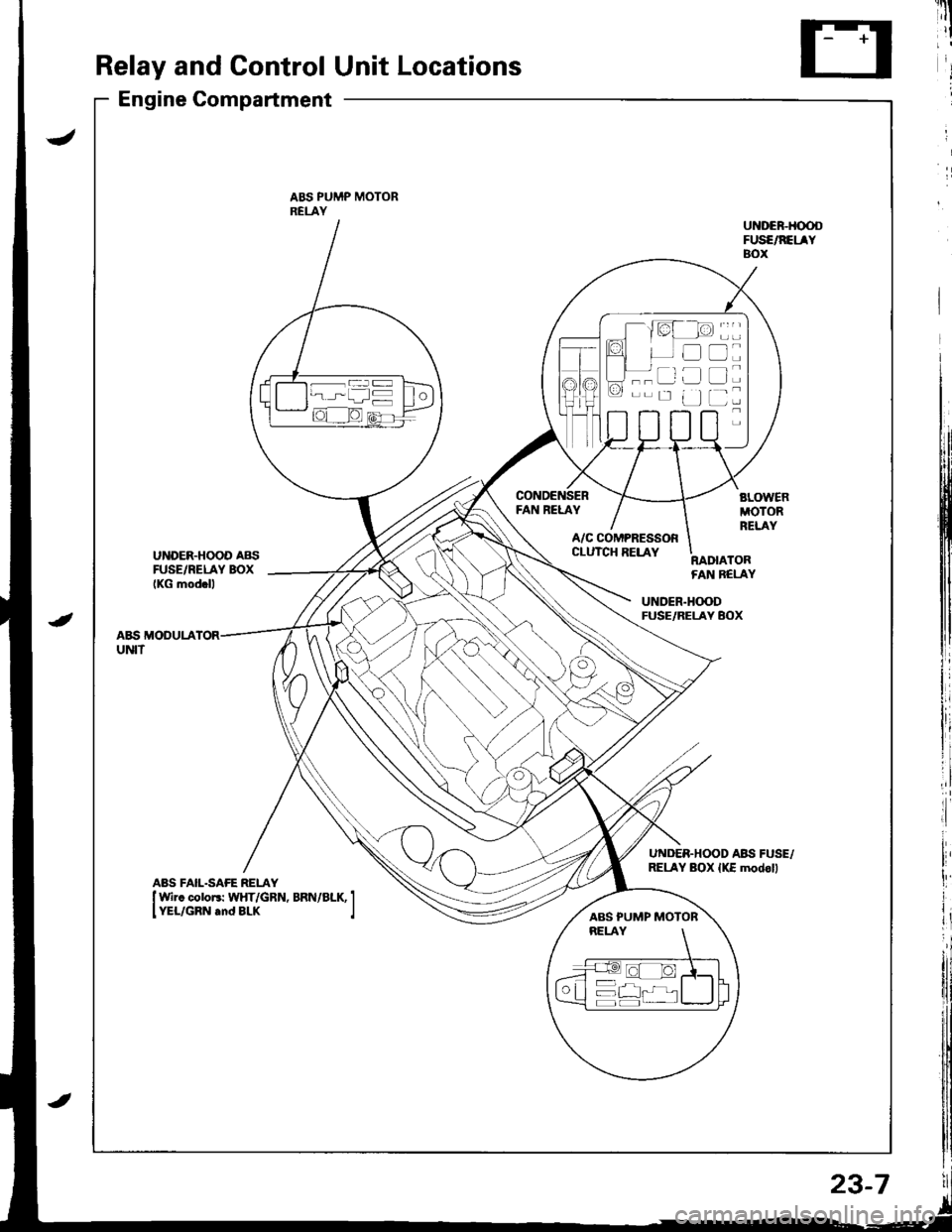
Relay and Control Unit Locations
Engine Compartment
ABS PUMP MOTORRELAY
FAN RELAY
UNDER.HOOD AB{iFUSE/RELAY BOXIKG mod.ll
A/C COMPRESSORCLUTCH RELAYRADIATORFAN BELAY
UNDER.H(X)DFUSE/RELAY BOX
A&S MODULAUNIT
UNDER.HOOD ABII FUSE,/RELAY BOX {KE modoll
----ar:l
--r: u
D
tr
L]
ABS PUMP MOTOR
23-7
Page 1065 of 1681
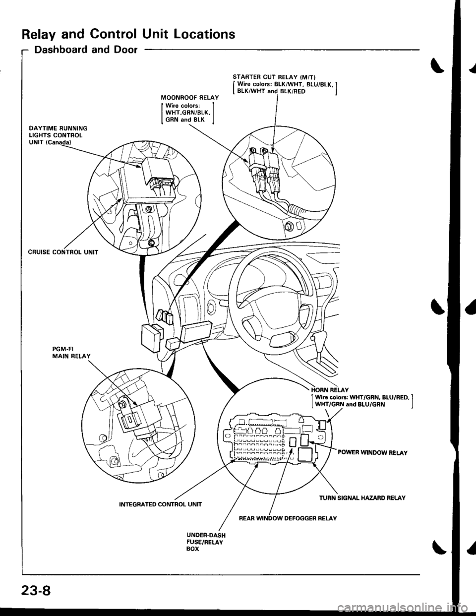
Relay and Control Unit Locations
Dashboard and Door
CRUISE CONTROL UNIT
PGM.FIMAIN RELAY
STARTER CUT RELAY IM/TI
I Wire colors: BLK/WHT, BLUi 8LK, II BLK/WHT and BLK/RED jMOONROOF RELAY
Wire colors:WHT,GBN/BLK,GRN and 8LK
I Wir. cotoF: WHT/GRN, BLU/RED, I
lWHT/GRN and BLU/GRN I
POWER WINDOW BELAY
23-8
INTEGRATED CONTROL UNIT
Page 1066 of 1681
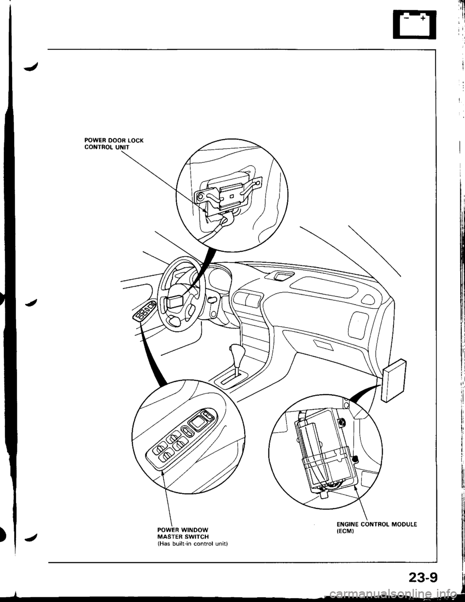
POWER WINDOWMASTER SWITCHlHas built-in control unitl
Page 1067 of 1681
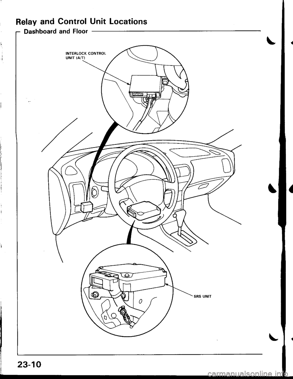
Relay and ControlUnit Locations
Dashboard and Floor
INTERLOCK CONTROLUNIT {A/T)
SS
23-10
Page 1068 of 1681
'u
il'
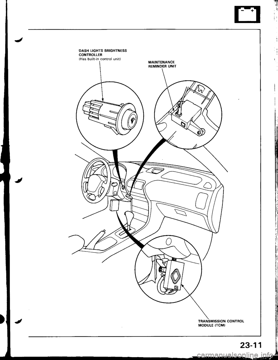
DASH LIGHTS BRIGHTNESSCONTROLLER(Has built-in control unit)MAINTENANCEREMINDER UNIT
MODULE ITCMI
23-11
Page 1069 of 1681
Relay and Control Unit Locations
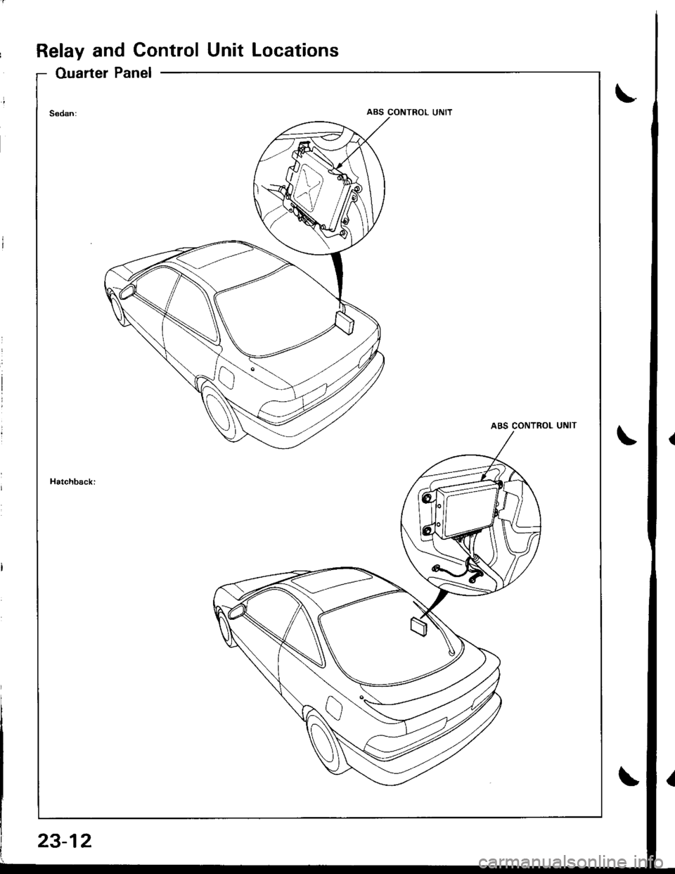
Ouarter Panel
ABS CONTROL UNIT
23-12
Page 1070 of 1681
Connector ldentification and Wire Harness Routing
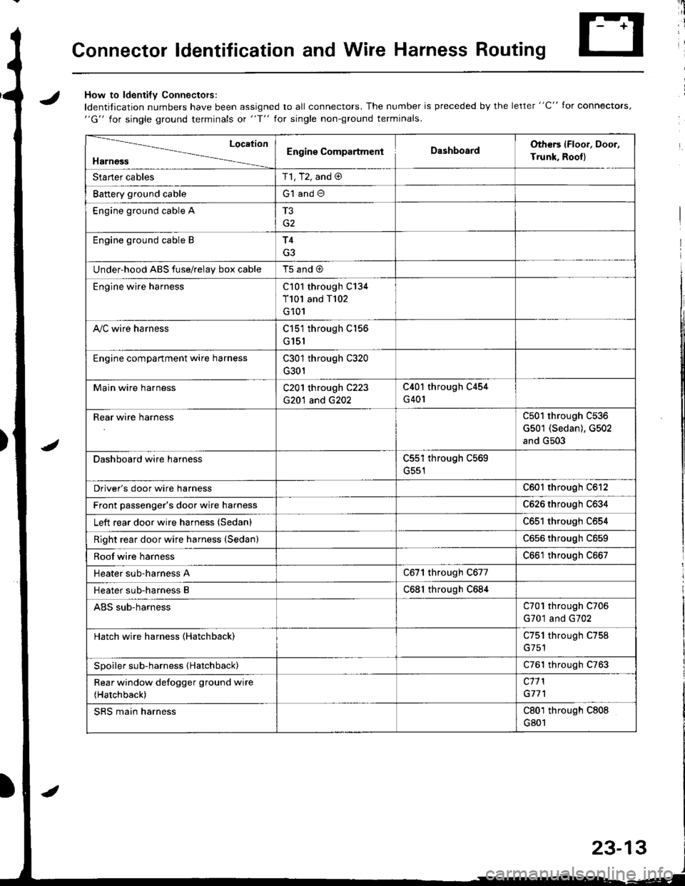
JHow to ldenti{v Connectors:
ldentification numbers have been assigned to all connectors. The number is preceded by the letter "C" for connectors,"G" for single ground terminals ot "f" lor single non-ground terminals.
/
Location
HarnossEngine CompartmentDashboardOthers (Floor, Door,
Trunk. Rooll
Starter cablesT1, T2, and @
Battery ground cableG1 and O
Engine ground cable A
G2
Engine ground cable BT4
G3
Under-hood ABS fuse/relav box cableT5 and @
Engine wire harnessC101 through C134
T101 and T102
G101
A,/C wire harnessC151 through C156
G151
Engine compartment wire harnessC301 through C320
G301
Main wire harnessC201 through C223
G20'l and G202
C40l through C454
G401
Rear wire harnessC501 through C536
G501 (Sedan), G502
and G503
Dashboard wire harnessC551 through C569
G551
Driver's door wire harnessC601 through C612
Front passenger's door wire harnessC626 through C634
Left rear door wire harness (Sedan)C65l through C654
Right rear door wire harness (SedanlC656 throughc659
Roof wire harnessC661 through C667
Heater sub-harness AC671 through C677
Heater sub-harness BC68l through C684
ABS sub-harnessC701 through C706
G701 and G702
Hatch wire harness (Hatchback)C751 through C758
Spoiler sub-harness {Hatchback)C761 through C763
Rear window defogger ground wire
(Hatchback)
c11 l
G77'l
SRS main harnessC801 through C808
G801
23-13
Trending: Right wheel, C506, Timing, glove box, Obd, air condition, height


