indicator HONDA INTEGRA 1998 4.G Workshop Manual
[x] Cancel search | Manufacturer: HONDA, Model Year: 1998, Model line: INTEGRA, Model: HONDA INTEGRA 1998 4.GPages: 1681, PDF Size: 54.22 MB
Page 1365 of 1681
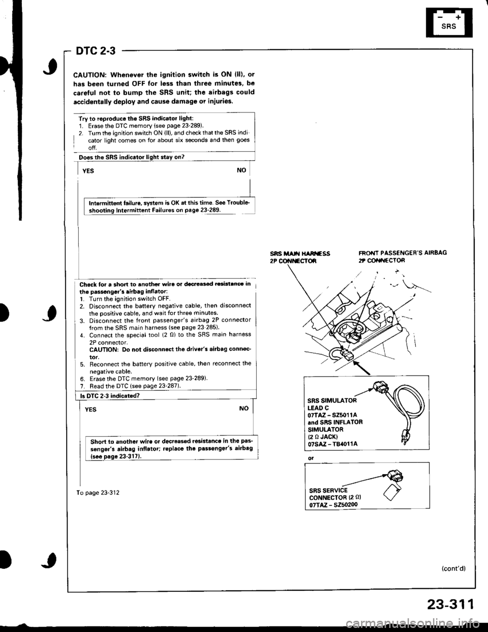
DTC 2-3
CAUTION: Whenever the ignition switch is ON (ll), or
has been turned OFF for less than three minutes, be
careful not to bump the SRS unit; the airbags could
accidentally deploy and cause damage or injuries.
Try to reproduce the SRS indicatol light:1. Erase the DTC memory (see page 23-289).
2. Turn the ignition switch ON (ll), and check that the SRS indi
cator light comes on for about six seconds and then goes
off.
Doos th€ SRS indicator
Chsck loa a short to anothcr wirc or dacacelod rarinanc. in
the passongGr'3 airb.g inflator:1. Turn the ignition switch OFF.2. Disconnect the baftery negative cable, then disconnect
the positive cable, and wait for three manutes
3. Disconnect the front passenger's 6irbag 2P connector
{rom the SRS main harness (see page 23 285)
4. Connect the special tool (2 0) to the SRS main harness
2P connector,CAUTION: Do not disconnect the drive/s .i.bag conn€c_
tor,5. Reconnect the batterY positive cable, then reconnect the
neoative cable.
s*i M t{ HIArfss2P @r{t*cTd
FNO'IT PASSENGER'S AIRBAG
2t @tat{ccTon
)
lntermittent failur€, svstem is OK ai this time. See Troubl6-
Intermittent Failures on page 23-289.
6. Erase the DTC memory (see page 23-289)
7. Read the DTC (see page 23'247l.
To page 23-312
|3 DTC 2-3 indicat.d?
Short to another wire or decreased resislance in the pas-
sengsr's airbag intlatot; teplace the p.$onger's aitbag
SRS SIMULATORLEAD C07TAZ - SZ50'r 1Aand SRS INFLATORSIMULATOR(2 0 JACK)07sAz-T84011A
ol
23-311
Page 1367 of 1681
\
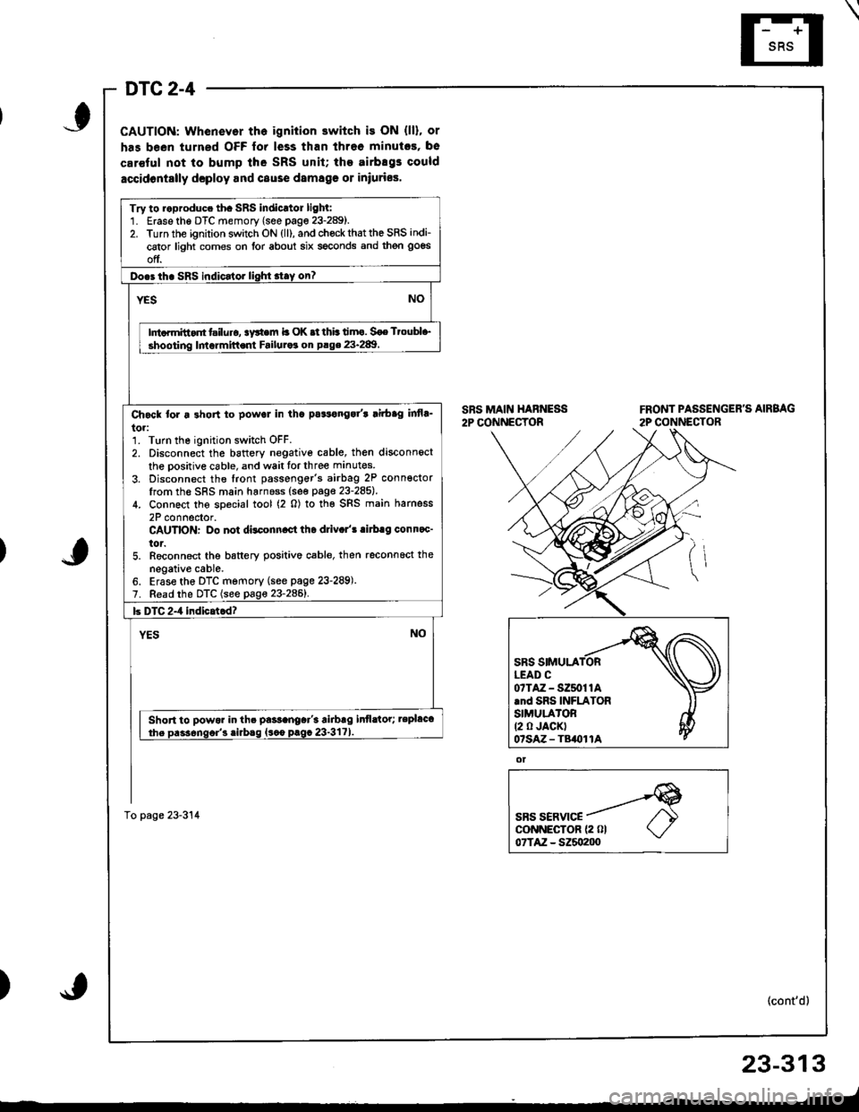
DTC 2-4
CAUTION: Whenevor th6 ignition switch is ON (ll), or
has been turned OFF for less than threo minutcs, be
car€ful not to bump lhe SRS unit; the airbEgs could
accidontslly dcploy and cause damag€ 01 iniuries.
SRS MAIN HABNESS2P CONNECTORFRONT PASSENGER'S AIRBAG
2P CONNECTOR
ot
SBS SERVICEcoNNECTOR {2 0l07TAZ - SZ5o200
(cont'd)
23-313
_-t
)
Try to roproduce th. SRS indicrtor lighl:1. Erase the DTC memory (see page 23-289).2. Turn the ignition switch ON (ll), and chock that the SRS indi-
cator light comes on for about six seconds and then goes
off.
Do.3 th. SRS indicator lighi stay on?
NOYES
Ini.rmitt.nt t iluro, !y*em b OK .t thb timo. Soe Ttoubl+,
shooting lmormittent Failuraa on P.ge 23.289
Ch6ck tor a 3hon to powol in tha pa3tonga/t lirbag infla_
to.:1. Turn the ignition switch OFF.2. Disconnect the battory negative cable, then disconnect
the oositive cable, and wait tor three manutes
3. Disconnect the front passenger's airbag 2P conn€ctorIrom the SRS main harnoss (see page 23-285).
4. Connect the soecial tool (2 0) to the SRS main harness
2P connector.CAUTION: Do not dilconn.ct tho driv.l'! .irb.g conn.c'
tor.5. Reconnect the battery positive cable, then reconnoct the
negative cable.6. Erase the DTC memory (see page 23-289).7. Read the DTC (see page 23-2861.
b DTC 2-4 indicatcd?
YESNO
Short to powor in th. pa$anoar'3 airbrg infldtor; tepl&t
the Dass6nqor'3 .irbaq {sco prgc 23-3171
To page 23-314
07TAZ-SZ50t1A.nd SRS INFLATORSIMULA'OR(2 0 JACKT07sAz - TB()11A
Page 1381 of 1681
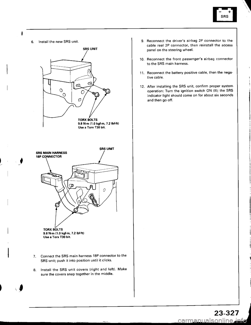
6, Install the new SRS unit.
o^ l- o
9.8 N.m 11.0 kgf m, 7.2Use a Torx T30 bit.
I
TORX BOLTS9.8 N.m 11.0 kgl.m, 7.2 lbf'ftlUse a Torx T30 bit.
7.Connect the SRS main harness l8P connector to the
SRS unit; push it into position until it clicks.
Install the SRS unit covers (right and left) Make
sure the covers snap together in the middle.8.
,l
\
10.
Reconnect the driver's airbag 2P connector to the
cable reel 2P connector, then reinstall the access
panel on the steering wheel.
Reconnect the front passenger's airbag connector
to the SRS main harness.
Reconnect the battery positive cable, then the nega-
tive cable.
After installing the SRS unit, confirm proper system
operation: Turn the ignition switch ON (ll); the SRS
indicator light should come on for about six seconds
and then go off.
11.
12.
Page 1383 of 1681
).1
Contents
How to Use This l\.4anual 1Circuit Schematics (see Circuit Index)Fuse/Relaylnformation 6ComponentLocation Photographs 201
Connector Cavity Numbers 202Connectorldentification 203
Ground-to-Components Index 6-6Wire Harness Routing 203Circuit ldentification lor ln-Line and Fuse Box Connectors
Circuit Index
Air conditionerAir delivery 61Blower controls 60Compressor controls 62Fans 63Anti-lock brake system (ABS) 44A/T gear position indicator 89Automatic transmission controls'98199 models 39'00 models 39-4Back-up lightsHatchback 110Sedan 110- 1Brake system indicator light
USA 71Canada 71-1Brake lightsHatchback 110-6Sedan 110-7Cargo area light (Hatchback) 114-3Ceiling light 114-2Charging system 22Cigarette lighter 155
Clock 154Condenser fan 63Console lights 114Cruise control 34Dash lights 1 14Daytime running lights 110-8Door open indicator 114-2Engine coolant temperature gauge 81Engine oil pressure indicator light 72Fog lights 110-14Front parking lights 110-11Front side marker lights 110-11Fuel gauge 81Fuse/relay boxUnder-dash 6Under-hood 6-3Under-hood ABS 6-5Gauges 81Glove box light 114Ground distribution 14Ground-to-Componentsindex 6-6Hatch open indicator '114-3
Hatch opener '134
Hazard warning lightsHatchback 'l l0-2Sedan 110-4Headlights 1'10-8Headlight switch 100HeaterAir delivery 61Blower controls 60Fanswith A,/C 63without A,/C 63-2Horns 40lgnilion key reminder 73lgnition system 20
204
lmmobilizer system ('00 model) 132lndicators 80Integrated control unit 70Interlock system'98199 models 138'00 models 138-1License plate lightsHatchback 110-12Sedan 110-13Lights-on reminder 73Low fuel indicator light 74l\,4aintenance reminder light 83l\iloonroof 122Odometer 81-1Power antenna 151Power distributionBattery to ignilion switch, fuses, and relays
Fuses to relays and components 10-2Power door locksHatchback '130
Sedan 130-2Power mirrorsHatchback 141Sedan 141-1Power windowsHatchback 120Sedan 120-2Programmed fuel injection system (PGM-Fl)'98199 models 23'00 models 24Radiator fanwith tuC 63without A,/C 63-2Rear parking lightsHatchback 110-12Sedan 110- 13Rear window defogger 64Seat belt reminder 73Security system 133Speedometer Il-1Spotlights 114-2Starting syslemAutomalictransmission 21l\.4anualtransmission 21-1Stereo sound system 150Supplemental restraint system (SRS) 47Tachometer 81- 1TaillightsHatchback 110-12Sedan 110-13Trailer lighting conneclor 118Trunk lid open indicator 114-3Trunk light (Sedan) 114-3Turn signal lightsHatchback 110-2Sedan 110-4Vehicle speed sensor (VSS) 33Wiper/washerFront 91Rear 92
10
).1
I
Xr
12Fg oAmerican Honda Motor Co., Inc. - All Rights Reserved Service Communications 275 pages
Page 1384 of 1681
)
)
How To Use This Manual
The next few pages describe how this manual is organized. They also
exolain what kind of information the manual contains, what that
information means, and how to use it to troubleshoot electrical problems.
Circuit schemalics break the entire electrical system into individual
syslems, like the Low Fuel Indicator Light on the next page.
Only electrical components that work together are shown together,
so you won't be distracted by unrelated wires.
Explanations of the abbreviations and symbols used in the schematics
begin on page E. You'll need to know what they mean before you can use
a schematic effectively.
Page 1401 of 1681
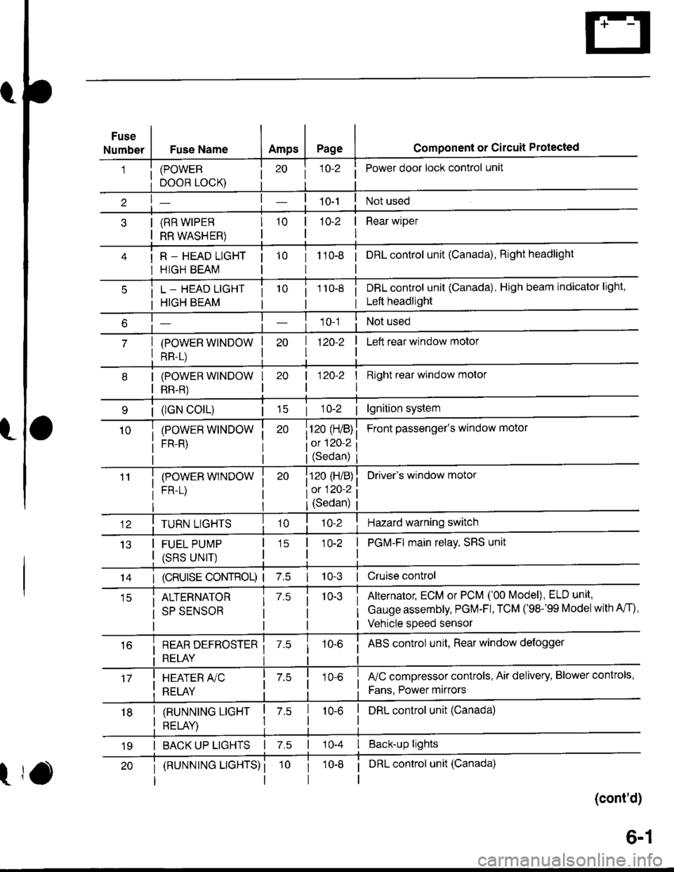
Fuse
NumberFuse NameAmpsPagecomponent or circuit Protected
(POWER
DOOR LOCK)
(RR WIPER
RR WASHER)
R _ HEAD LIGHT
HIGH BEAM
j 1o-2Power door lock control unit
10-2 | Rear wiper
I
tto-e i onLcontrol unit (Canada), Right headlight
L _ HEAD LIGHT
HIGH BEAM
(POWER WINDOW
RR-L)
i 1 10-8i DRL control unit (Canada), High beam indicator light,
i Left headlight
1 0-1Not used
| 1zo-z
I
I Left rear window motor
| (lGN colL)| 15
(POWER WINDOW
FR-R)
(POWEB WINDOW
FR-L)
I Right rear window molor
I
Front passenger's window motol
Driver's window motor
| 120-2
i120 (H/B)
iot 120-2
l(Sedan)
i120 (H/B)
l0:120 ?
IJ13
TURN LIGHTS
FUEL PUMP
(SRS UNIT)
(Sedan)
'lo-2Hazard warning switch
1O-2 | PGM-FI main relay, SRS unit
I
14I (cRUlsE coNTRoL) | 7.510-3 | Cruise control
ALTERNATOR
SP SENSOR
7.510-3Alternator, ECM or PCM ('00 Model), ELD unit,
Gauge assembly, PGM-Fl, TCM ('98-'99 Modelwith A/f),
Vehicle speed sensor
i REAR DEFBOSTER ii RELAY i
10-6i ABS control unit, Rear window defogger
I HEATER A/C
: RELAY
fuC compressor controls, Air delivery, Blower controls,
Fans. Power mirrors
I tnururutruc ucxr I z.s
I otrt av I
I DRL control unit (Canada)10-6
I BACK UP LIGHTS | 7.s | 10-4 I Back-up lights
t
(RUNNTNG LTGHTS) ii DRL control unit (Canada)
(cont'd)
19
6-1
Page 1455 of 1681
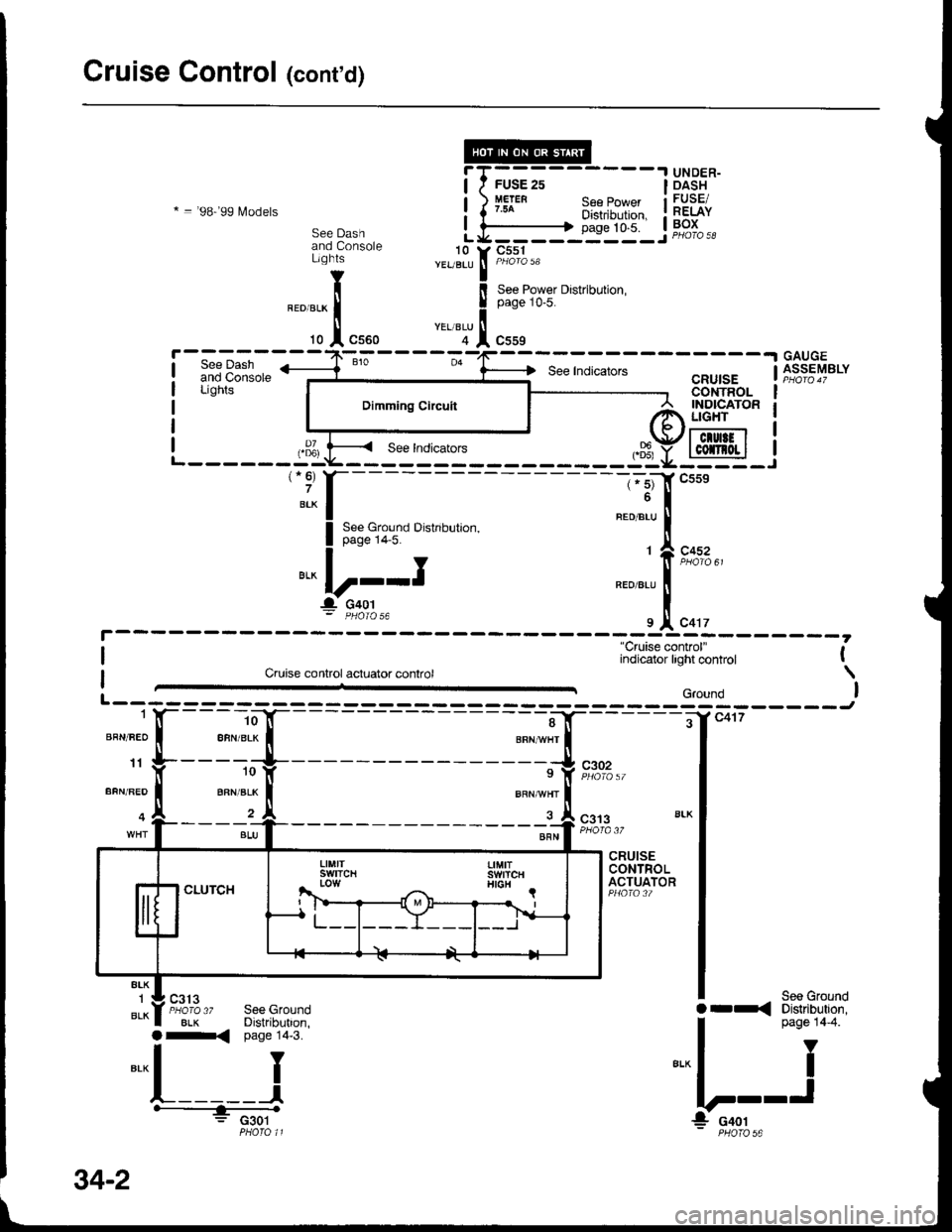
Cruise Control (contd)
.I UNDER-
* = '98-'99 lvlodels
DASHFUSE/RELAYBOX
T
!
l
L10YEUBLU
YEL/BLU
See Dashand ConsoleLights
See IndicatorsGAUGEASSEMSLYCRUISECONTROL
"Cruise control'Indicator tght control l-
Cruise control acluator control \
BRN/FEO I ABN'BLK T aRNAA/HT
rr g-----:^1f --'rf, csoz1oy s y iio",'o,,BFN/FED I BFN'BLK f BRN^n/HT
o A_____r_A s__l csrswxr I sru I """|'PrJic ''
CRUISECONTROLACTUATOR
8LK1
BLK8LK
S€e Grolnd
a-< page 14'3.
Or-< Distibution,
|
*n;'"
e.^l I
!---J- PHOTO 56
See GroundDistribution,
: c301
! | Dimminscrrcurt |� lISiPto" !I r I r e r:::::_ |
| ,,31 f---- see Indicators -^\J'llclultl | :
L------:-:Y----- -----sLt-95-.i':::f----
I 3:3"9i;,To o'"o,0',,""'
"'^|,2-.-.I
g.. c+or- D4OIO.6 9
34-2
Page 1457 of 1681
Cruise Control (cont'd)
- How the Circuit Works
The cruise control system uses mechanical and
electrical devices to maintain the car's soeed at a
setting selected by the driver.
System Description
The cruise control unit receives command signals
from the cruise control main switch and the cruise
control SevBesume switch. With the ignition switch
in ON (ll) or START (lll), voltage is provided to the
cruise control main switch. When you push the
switch to on, power is provided to the cruise control
unit and the brake switch.
The cruise control unit receives information about
operating conditions from the brake switch, the
ignition control module (lCM), the vehicle speed
sensor (VSS), and the clutch switch (manual
transmission) or the A,/T gear positton switch
(automatic transmission). The cruise control unit
then sends signals to the cruise conirol actuator
which regulates the throttle position to maintain the
selected speed. The control unit compares the
aclual speed of the car to the selected speed. The
control unit then uses the result of that comoarison
to oDen or close the throttle.
The brake switch releases the system's control of
the throttle at the instant you press on the brakepedal. The switch sends a signal to the control unit
by removing power from the normally closed brake
input (GRY wire), and providing power at the
normally open brake input (GRNMHT wire). The
control unit responds by allowing the throttle to
close. The clutch switch or the A/T gear position
switch sends a "disengage" signal to the control unit
that also allows the throttle to close.
The cruise control system will set and automatically
maintain any speed above 25 mph (40 km/h). To set
it, make sure the main switch is on and the switch
indicator is on. Then, after reaching the desired
speed, press the set switch. This sends a "set"
signal to the cruise control unit which, in turn,
controls the cruise control actuator to maintain the
set soeed.
When you push the SET switch and the cruise
control system is on, the "cruise control" ON
indicator lights up.
34-4
You can cancel the cruise control system by
turning the main switch off. This removes power to
the control unit and erases the set sDeed from
memory. lf the system is disengaged temporarily
by the brake switch, or clutch switch, and the car's
speed is still above 25 mph, press the RESUME
switch: the car will automatically return to the
previously set speed.
For gradual acceleration without pressing the
accelerator pedal, push the RESUME switch and
hold it there. This will send an "acceleration" signal
to the control unit. When you release the switch, the
system will be reprogrammed tor the new speed. To
slow the car down, push the SET switch in and hold
it there. This sends a "deceleration" signal to the
control unit, causing the car to coast. When the
desired speed is reached, release the SET switch.
This reprograms the system for the new speed.
Reter to the Service Manual (Section 23, Electrical)
for specific tests or troubleshooting procedures.
Page 1465 of 1681
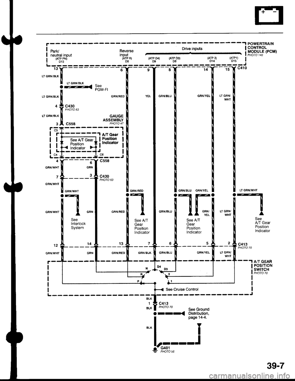
.I POWERTRAIN
!1it1g,,,"",,, n"J,:'"" &!fr3tl[Eb"'rI ireuiar input inpq1 -l
i *ts5-' 6r"F) ( r$o4) (AT&Do) Sf.a $lut Il------- --------J
fiF4H{:{
'ffi$l
Il lI
if """1 """"."[f, 1"".""ilfi '**[l
see I ll see nn I ll see nn ll I 91"tniertoct I I il;;" I t c;;;" I I Arcear
sysrem I ll F;i,on I ll ioJtion I I Positron
i*iidlj6|' I ll inoii"1o, i ll Indicator
12 A ___ r1j---- 'r-^----'i --o-^----- -"lL- -= c413
onrwn I cFN I cFN nEo I cFN BLK I cFN BLU I GFNYEI I Lr GFN
-t--.I A/T GEAR
ALK
1ALK
orr-<
I POSTTTON
i swrTcHI P|1jTO 70
I
I
I
c413
*Lr-
See GrourdOistribution,page 14-4.
Y
I
.J
39-7
Page 1479 of 1681
A/C Gompressor Controls (conrd)
- How the Circuit Works
Battery voltage is supplied through fuse 56 to the
A,/C compressor clutch relay contacts at all times.
With the ignition switch in ON (ll), voltage is applied
to the coil of the A,/C compressor clutch relay
through fuse 17. When you push the A,/C switch
ON, and the heater fan switch is in posation 1, 2, 3,
or 4, a "ground" input is provided to the engine or
powertrain control module (ECM or PCM) through
the A,/C thermostat and the A,/C pressure switch.
The A,/C compressor clutch relay is grounded by the
engine or powertrain control module (ECM or PCM).
When energized, the A,/C compressor clutch relay
allows battery voltage to turn on the A,/C
comDressor clutch,
The A,/C ON indicator light comes on when the A"/C
system is requested.
A,/C Thermostat
The A,/C thermostat is located on the evaoorator
housing. The AJC thermostat turns off the A,/C
compressor clutch if the temperature at the
evaporator goes below 3'C (37'F). This prevents
condensation from freezing on the evaporator fins
and blocking the air delivery into the passenger
compartment. The blower motor will keep running
when the sensor lurns off the compressor.
A,/C Pressure Switch
The A,/C pressure switch is located in the condenser
outlet line where refrigerant is in a high
temperature/high pressure liquid state. The switch
will sense abnormally high or low pressure, and
open the circuit. This removes ground, and the
compressor will stop running.
Refer to the Service Manual (Section 22,
Air Conditioning) for specific tests or
troubleshooting procedures.
62-2