indicator HONDA INTEGRA 1998 4.G Workshop Manual
[x] Cancel search | Manufacturer: HONDA, Model Year: 1998, Model line: INTEGRA, Model: HONDA INTEGRA 1998 4.GPages: 1681, PDF Size: 54.22 MB
Page 1496 of 1681
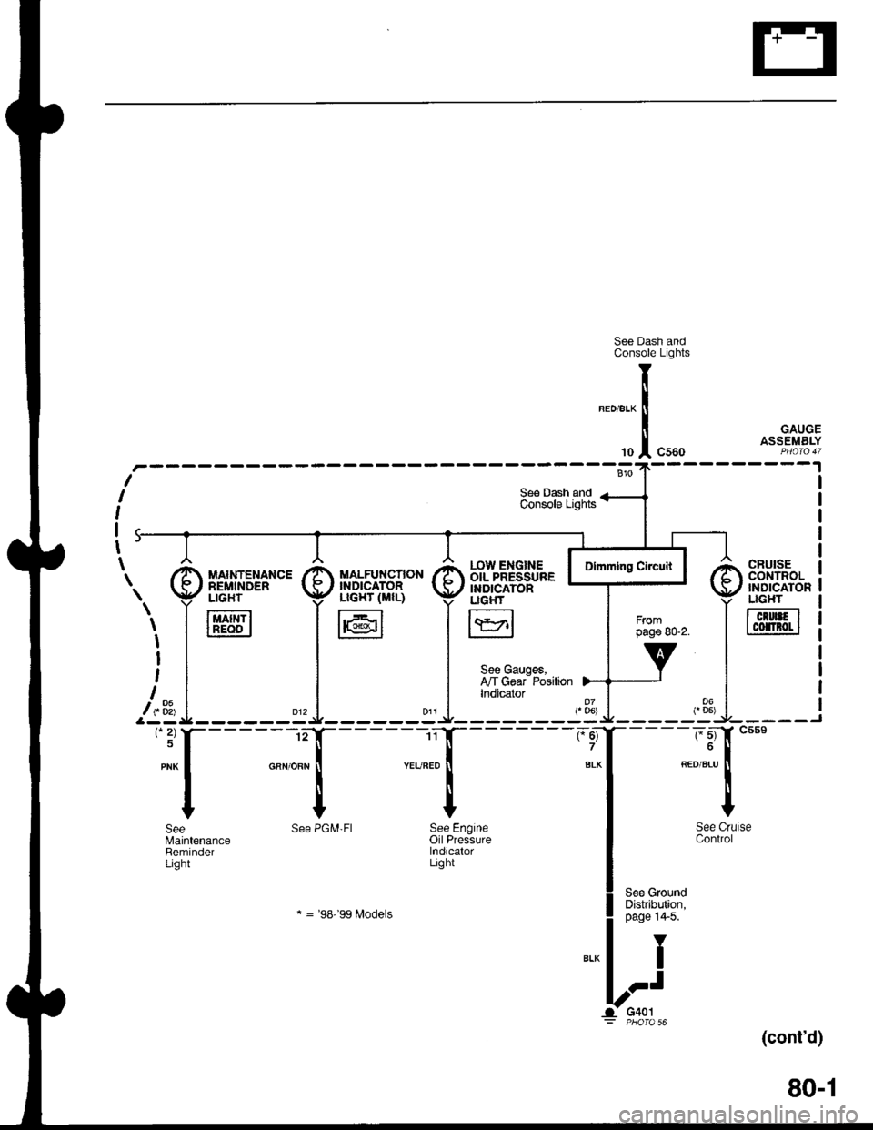
See Dash andConsole Lights
GAUGEASSEMBLY
(cont'd)
80-1
CRUISEcor{TRoL'NDICATONLIGHT
TcrurFlI cofnot I
r.ow ENGTNE IOIL PRESSURE IINDICATORLIGH'
I\YrlL:J
See Gauges,I'lT Gear PositionIndicator
"ff
I
See CrlControl
See GroundDistribution,page 14'5.
Y
I
.-t
G401PHO|O 56
T
li
'"1
See PGM'FI See Engineoil PressurelndicalorLight
* = '98-'�99 Modets
SeeMaintenanceReminderLight
\. I [,'d['*"' I il]i"fl".,B* I
i,1_* =i^ .l
'*f----l- :{
Page 1497 of 1681
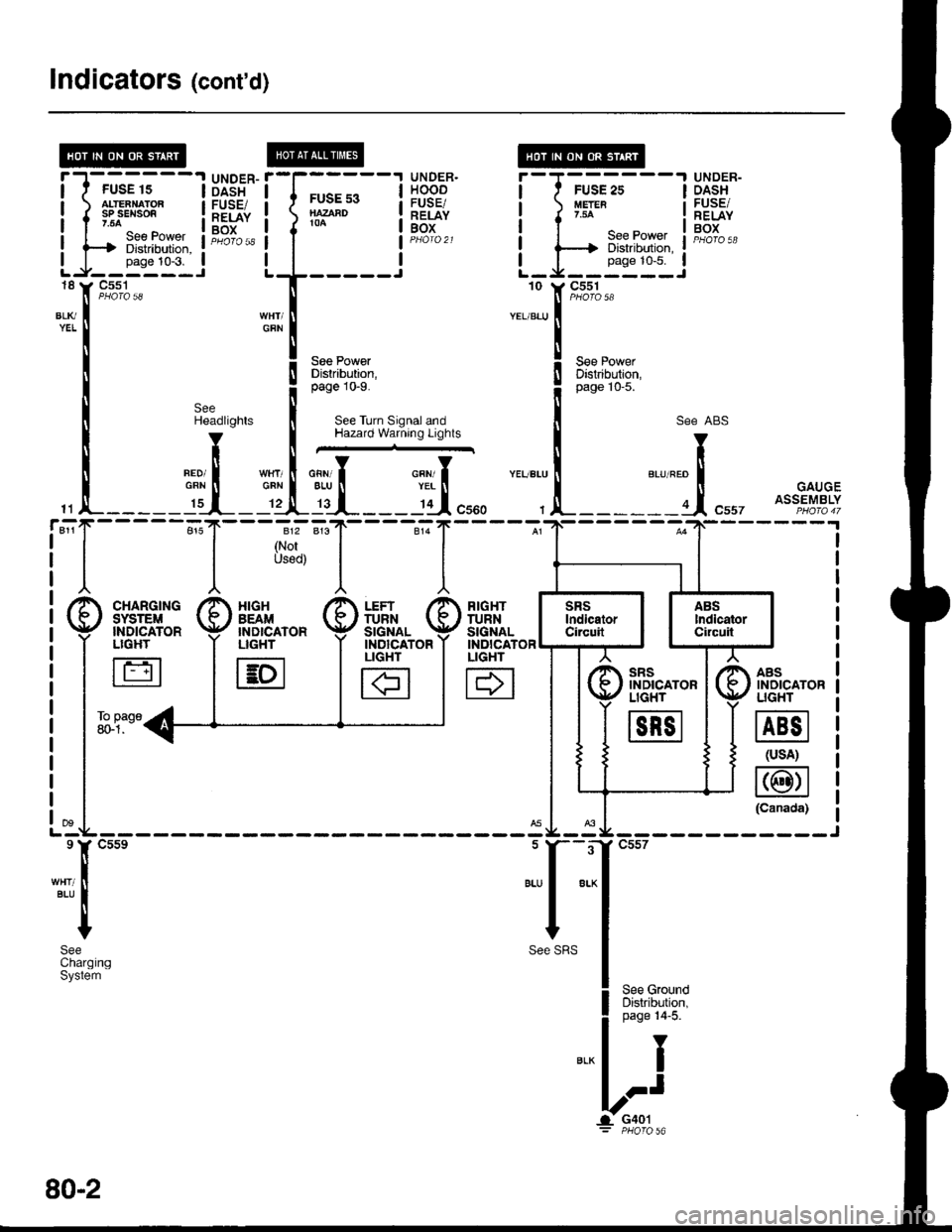
Indicators (cont'd)
@
tt
t(
tt
lt
tl
"-T
!T
!I
gI
IUNDER.HOODFUSE/RELAYBOX
UNDER-DASHFUSE/RELAYBOX
l-J-rr-trr1---l
LJi!*''i
DASHFUSE/RELAYBOX
FUSE s3NAZAAD104
18
BLl(YEL
11
811r
See PowerDistrabution,page 10-9.
See Turn Signal andHazard Warning Lights
SeeHeadlights
V
tlneoi IGRN tI._ I':r__
I
{
I
812
(NorUsod)
___l'd",,,
RIGHTTURNSIGNALINDICATORLIGHT
H
AASINOICATORUGHT
@
(usA)
@(Canada)
"..,::,f
t*'
! ,"" ro*o
il
;:i:it''l
see ABs
"r""." I "., "." trt
, !-------a.1, "uu, ott?fl%tf
sRsINDICATORLIGHT
m
XIGHBEAM'NDICATORLIGHT
E
FUSE 15ALTEANATORsP sEl{son.54
---t Diskibution, :
-rr"t:t--i'C5s1
Page 1499 of 1681
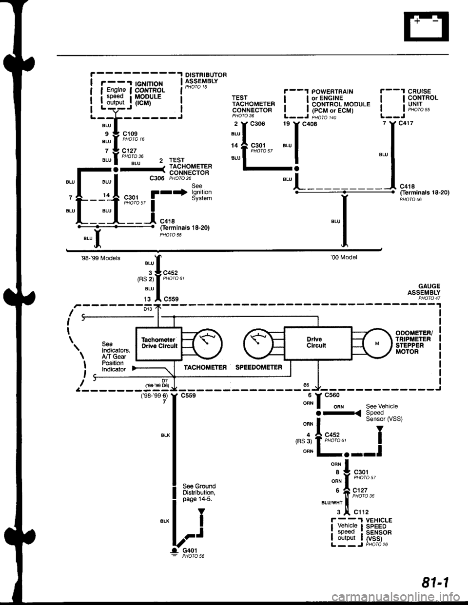
DISTRIBUIOR
r - -'l tGNtT|oN | 39;s;t'rarvI Engine I COI{TFOL l"* " "
i sp€ed i MoDULE a
Louteut .j (tcm) i
'-;t;----i
',i'l:i::'"
".ul""ollju 2 rEsr
-l-_1;.11=1==
-L-:ttt
'r*'i*'*
"-l
(ferminals 18-20)
YBLU II
Oerminals l8-20)
'98-'99 Models
r-------fr:fl;,,
'00l\4odel
GAUGEASSEMBLY
I
I
t
\
9-
SseIndicators,,ry'TGearPositionlndicatof
ODOIIETER/TNIPi,|:TENSTEPPERMOTOR
07f9+'99 D6)
\
I
t
I
(98-'�99 6)7
v------ -"u Jl,-------------J
f
csse ""t" f
"tt"t""
see vehicte
|
":^i:33i#'""'
I '.'3'tFffi"' I
I ""n l-.--l
|
*^l
| .^^^.^..-. ",',f n%',
l** ii*i
Lri ibr,li;tfi
81-1
Page 1503 of 1681
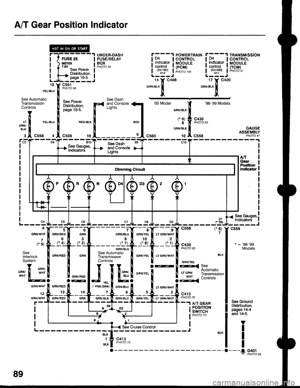
A/T Gear Position Indicator
UNDER.DASHFUSE/RELAYBOXPHOTA 58
POWERTRAIN TRANSMISSION
I D4. I coNrRoL | tr. lcoNrRoL
L$"r:j HS}H Lrulij
frBfii:'
*-1.'-f,"*' *,::-f,"*'c551
Ses PowatDislribution,page 10-5.
See Dashand ConsoleLights
'00 l4odel
't0
:ql
'98'�99 [4odels
c430
c558
410S€e Gaug€s,lndicators
See Dashand ConsolaLights
GAUGEASSEMBLY
A/r IGsa. IPoEltlon :lrdlcator I
I
I
I
I
I
I
I-t**r*",!
Indicdo6 |
I
I
L---ac9
c559
* = 98-99Models
Sgs GroundDistributon,pages 'l4{
and 1+5.
4
GRNAVHT
(" 5)
SeelnterlockSystem
Yi GBN/",i,ll I wHr
'12
GFNA!/HT
c413BLK1
BLK
V
T
I
I- - --a_ G40 t= PHOTO 56a
See PowerDiBaibution.
89
Page 1504 of 1681
- How the Circuit Works
With the ignition switch in ON (ll) or START (lll),
voltage is applied to the A,/T gear position indicator.
The A,/T gear position switch provides a ground for
each position. As an input is grounded, ils indicator
light comes on. lf you se,ecl B, tor example, ground
will be applied to the input of the A,/T gear position
indicator, and the R indicator bulb will come on.
With the headlight switch in PARK or HEAD, voltage
is applied to the RED/BLK wire terminal. this
changes the indicator panel illumination from lixed
to controlled by the dash lights dimmer inpul
through the RED wire.
When the lransmission ('98.�99 models) or
powertrain ('00 model) control module (TCM or
PCM) detects an abnormality in the automatic
transmission control system, or when you request
diagnostic trouble codes through the service
check connector, the TCM or PCM will make lhe D4
indicator light blink.
Refer to the Service Manual (Section 14,
Automatic Transmission) for soecific tests or
troubleshooting procedures.
89-1
Page 1517 of 1681
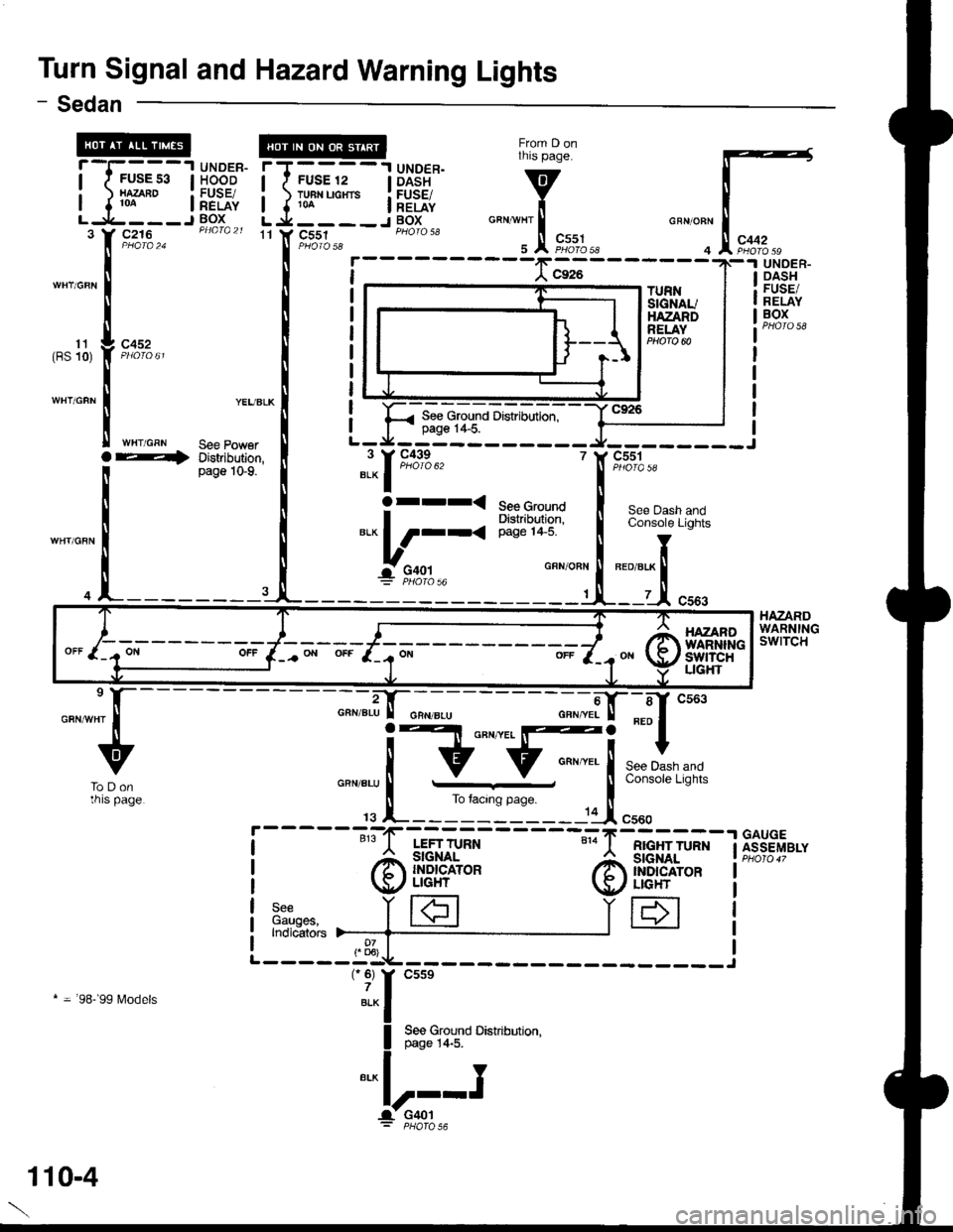
Turn Signal and Hazard Warning Lights
From D onthis page.
v
i"""*l'.!,
F,*%.,r
- Sedan
11 Y C551GRN/OFN
4
rT----'l UNDER.I I FUSE 12 | DASH
i ) TH"uo"'. i[EiE{,L j.___-J BOXc216
c452
WHT/GRN
TURNSIGNAUHAZANDRELAY
UNOER.DASHFUSE/RELAYBOX
HAZARDWARNINGswtTcH
11(BS 10)
See Ground Distribution,page 1+5.
YEUBLK
See PowerDistribution,page 1G9.
r andLights
' c551
Ser
BED/8
i5't)IQ 5A
See Dash aConsole LiC
Ioret.x ll
lt.-1 c:
BED/8LK
7
GFX/OBN
'|
See GroundDishibltion,page 1+5.
"l-1m*"
arrr<
*.L_;,,-'
---";;|tr--sf cs63
F[ ***,,,*
page i
.-----11I cr"o
RIGHT TURN
@ffiH*
IH
----";";.i-tr-;;--
! Elt o"n '
lv:;..=--j
-G
rs l_______-------:-'1F
LEFT TURN
@il!H'*
3:",n"", i|€]Indicators )--_-_-{___
-"-u
ToDonrnrs page.
GAUGEASSEMBLY
* = 98-'99 l\4odels
HAZANOWARNINliswtTcHUGHT
110-4
Page 1522 of 1681
![HONDA INTEGRA 1998 4.G Workshop Manual - Canada Only
UNDER-OASHFUSE/RELAYBOX
T@-];----
_ti:___:_c440
;
J
j
r-----
I See Power: Distribution,I page 10-8.
I
IL-----
FUSE 20{FUNNING LIGHTS)
See BrakeSystemIndicalor Light
c439
c41sc416
c416
ar HONDA INTEGRA 1998 4.G Workshop Manual - Canada Only
UNDER-OASHFUSE/RELAYBOX
T@-];----
_ti:___:_c440
;
J
j
r-----
I See Power: Distribution,I page 10-8.
I
IL-----
FUSE 20{FUNNING LIGHTS)
See BrakeSystemIndicalor Light
c439
c41sc416
c416
ar](/img/13/6069/w960_6069-1521.png)
- Canada Only
UNDER-OASHFUSE/RELAYBOX
T@-];----
_ti:___:_c440
;
J
j
r-----
I See Power: Distribution,I page 10-8.
I
IL-----
FUSE 20{FUNNING LIGHTS)
See BrakeSystemIndicalor Light
c439
c41sc416
c416
arr<
DAYTIMERUNNINGLIGHTSCONTROLUNIT
c302
1
WHT/NEO
WHT/FEO
DAYTIMERUNNINGLIGHTSRESISTOR
c307c440
.I UNDER.DASHI FUSE/RELAYI 8OXI Pqofa 53
c504
18
r
I
I
1
A C508
l-l-l PARKINGI ' I BRAKE| .( | swrrcH| ..- t I Closed with4 parking brake- applreo.PHAfO 71
c301
See GroundDistribution,page 14-4.
Y
I
I
a:."-
Lights-on Batteryinpul
Headlight control
lgnitionBrake system indicatorlight control
GroundParking brake input
r-910-1-
1 10-9
Page 1523 of 1681
Headlights (cont'd)
- How the Circuit Works
Low Beam OperationRefer to the Service Manual (Section 23, Electrical)
for specific tests or troubleshooting procedures.
With the headlight switch in HEAD and the dimmer
switch in LO, current flows through the headlight
switch, fuse 21 , tuse 22, and the low beam
filaments to ground, and the low beams come on.
tligh Beam Operation
With the headlight switch in HEAD and the dimmer
switch in Hl, current flows through the headlight
switch, dimmer/passing switch, fuses 4, 5, 21, and
22, and the low and high beam filaments to ground,
and the low and high beams come on.
Current also tlows through the high beam indicator
light to ground. The high beam indicator comes on
to remind the driver that the high beams are on.
Flash operation
The flash feature works with the headlight switch in
OFF, PARK, or HEAD (low beams). When you
move the flash-to-pass switch to ON, current flows
through the switch, fuses 4 and 5, and the high
beam filaments to ground, and the high beams
flash. The high beam indicator also flashes during
the flash oDeration. The flash function has no effect
it the high beams are already on.
Daytime Running Lights Day Operation
When you turn the ignition to ON (ll) with the
parking brake released, the daytime running lights
control unit supplies battery voltage at the
WHT/RED wire. This voltage is applied to the high
beam headlights through the daytime running lights
resistor. Each high beam headlight receives less
than battery voltage causing them to come on al
reduced brightness.
lf the parking brake is set, a ground signal is applied
to the daytime running lights control unit at the
RED/GRN wire. It the parking brake is set when you
first turn the ignition switch to ON (ll), the high beam
headlights will remain off until you release the
parking brake. Once the high beam headlights are
in day mode, setting the parking brake will not
cause the headlights to turn off . When low or high
beam operation is requested, baftery voltage trom
the headlight switch is applied to the daytime
running light control unit via the RED/vVHT wire.
The daytime running light control unit then
discontinues the daytime running light mode.
1 10-10
Page 1527 of 1681
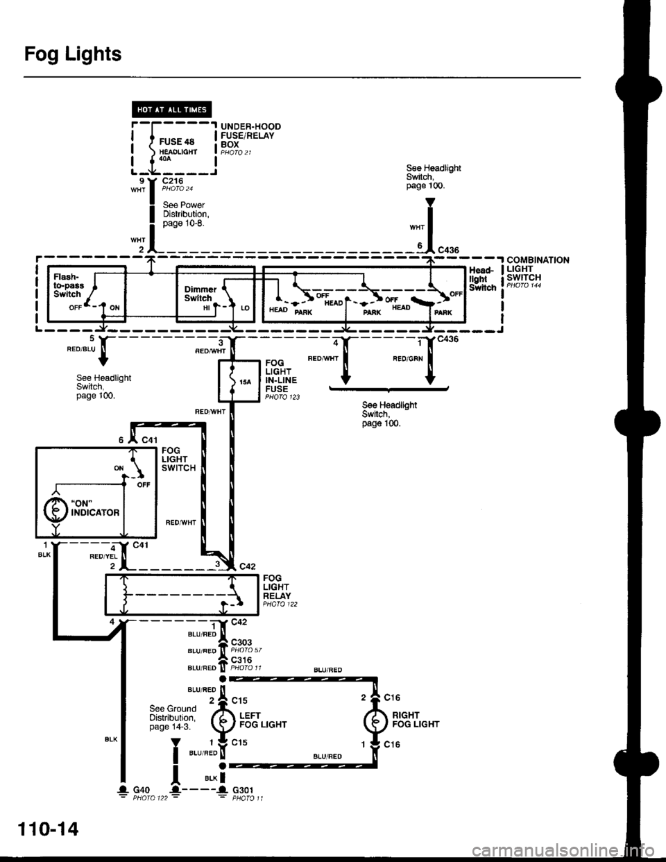
Fog Lights
UNDER-HOODFUSE/RELAYBOXi-f;;-| neroucrt
!__L':___
:;i!'r.
6€e HeadlightSwitch,page 10O.
Y
I
-.1.*.
Flash.to-pasE ISwitch /
orrl-t o"t*
oir.r, {-Swltch \",I-J -
lt:
-- -'t coMBtNATtoN1H€8dT I LIGHT
lggltl"" iP#[9]l
*,JI-
See HeadlightSwitch,page |00.
ON
"oN"
INDICATOR
FOGLIGHTIN-LINEFUSEPHOfO 123
FOGLIGHTREI.AYPHATO 122
See HeadliohtSwitch,page 100.
cl6
RIGHTFOG LIGHT
------Tl'c42
elurneo ll
".u,".of, "t"to% u,
A csroBLU/REO ll PHO|O tr
Ut",'ry*
"'fi
',ua'r.,o
"'
110-14
..- c4o -a-----l c3o1: PHoro 122 : : pHaToll
Page 1530 of 1681
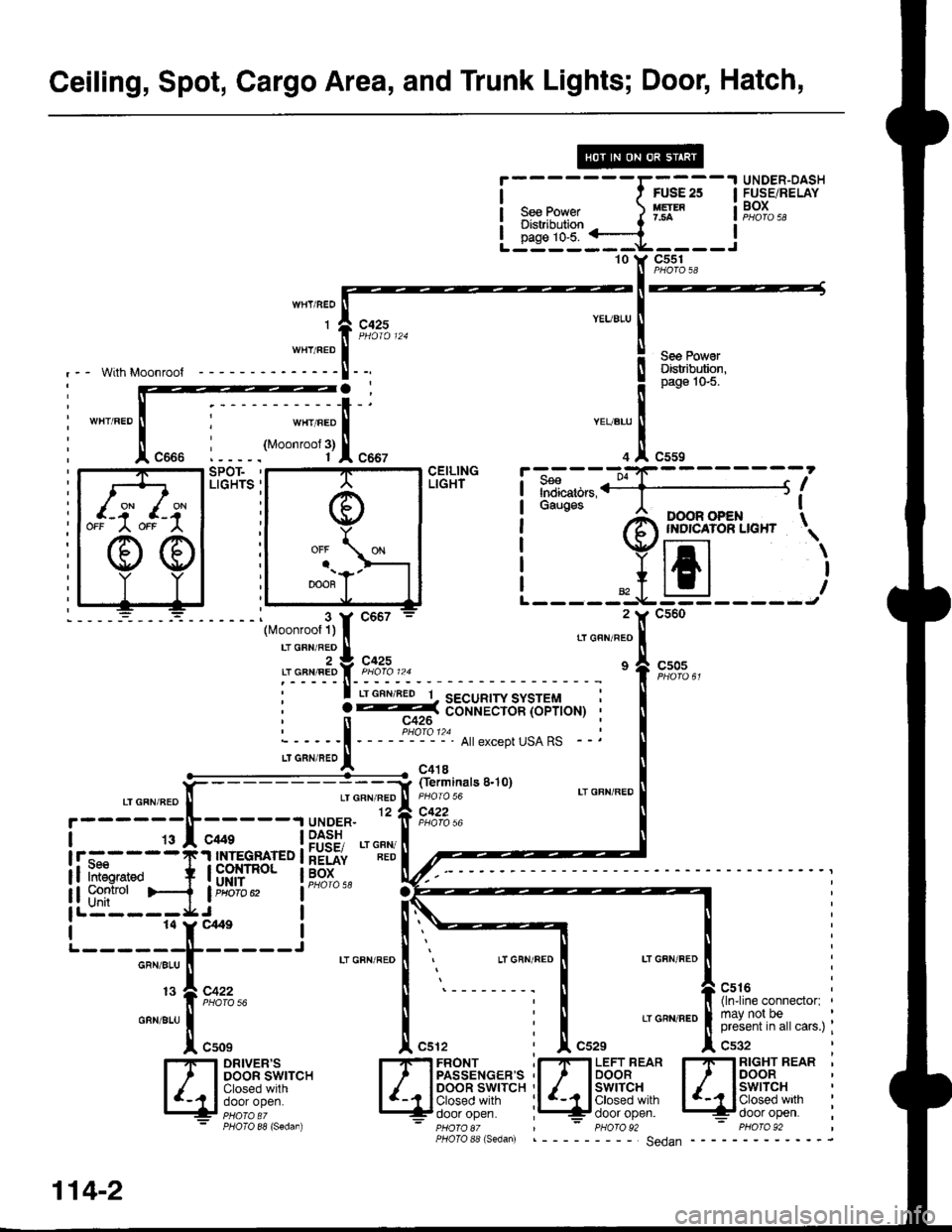
Ceiling, Spot, Cargo Area, and Trunk Lights; Door, Hatch,
i
- - - - - - -rffi
;
-
I H,!8",klf;""
I s""Po*"r. ) Ifl* i!,?t,,: Distribution t '-
!-id"i::=a----l'10 Y C55110 Y C5s11l PHOTO aA
-l--
IYEUBLU
I
i qpq Fv"'ll uElnDuron.! page'lo-5.
"Tl",,,
Indicators,ii1;](;;;' I II'OOR OPEN TINDICAIOR LIGHT \
tJEJ
With Moonroof
c425
wHr/BEoJl
::'::l[
LIGHTS '
-:_ __i (ferminats 8.10)
CEILINGLIGHT
,-, o"n "a9 [ rroro ro LT GFN'REDGFN/REO12 a C422if pForo )6
| _9I _c*s __ |PfSE, .'"""
t!-f."----T'! IU.E9F FD I hEiii iiD
if ifr*"o + l8Rllr"o' ti;91".. l1---
i i i:tr#i">-{ i"usfl. lai6iose
lL:---=*J-.^ |
'---=r,f;---J .'""""."i
.-E
.,o"""."f.u,.
I-I-I DRIVER'S I-IF] FBONT .I-IFI LEFT REAR I-IFI RIGHT REAB 'l, IDooRswrrcH l, IPASSENGEBS,I I loo.|orB" l/ ISSP;B, :
ll+lF.":"::r!!r lglp;?"',"i,:;i'''"" il /-r|il{':!,sf l '-11:$"|I,lr
i
13?,c:::""" I
'--------;
I t{r"rn".iil""onn""to., ,
o"n".u| | : | 'oa',n."|[3r,J#,1?,,"",",;
| "uor ,f[ cu', i J[ cszs ,1, c'g,
PHOIO 88 (Sedan) - pHOrO 8t | - PHOrO 92 - PHO|O 92PHoIo 88 (s6dan) ___ Sedan
a-t c-{OFF
OFF A
";flxl
3::; ;;il;;;
::"T{ ;,
2 Y C560
' ? --=:( d-o-n-r.iiiicin ioprroHr, n c426
:_---_i - _ _ _:Plo_'?. A||exceptusARs _
LTGRN,BE'I - c4'r8
114-2