indicator HONDA INTEGRA 1998 4.G Manual PDF
[x] Cancel search | Manufacturer: HONDA, Model Year: 1998, Model line: INTEGRA, Model: HONDA INTEGRA 1998 4.GPages: 1681, PDF Size: 54.22 MB
Page 1181 of 1681
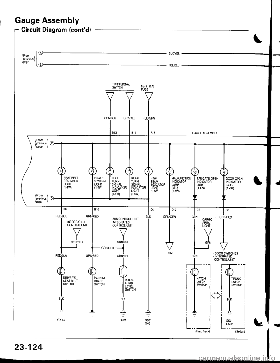
auge Assembly
Circuit Diagram (cont'dl
iG
BLK,IYEL
No.5 (10A)
V
IREO/GRN
I e,s
TURN SIGNALSWITCN
v--=v
tltl
tlGBN/BLIJ GRN,YEL
lltl
I e's I s,o
"i.uv"'T""
H^,J.**.GBN . INTEGRATEO
I coNrRor uNrT
,'T--l ffi--l
lI*ni lI*i
il i*i t i
i. li;, I
L__ i L:'�_" i(Hatchback) (Sedan)
| 012
GRNORN
vECM
louBLK
G20lG401
RIGNTTURNSIGNALINDICATORL]GHT(1.4w)
TAILGATE.OPENINDICATORLIGHT(1.4!9
RED/BLU GBN/RED| | . ABS CoN-FOL U\lTI .NTEGFATED I .INTEGBATED
|
*v^"
|
-'v*
| .roL-" I or*frro
ts Fo.''-,,-jBED/BLU GRN/RED GHNi RED
rrl
AAA
Yu'**- Y*,,r" Y**
l3$i;.?.'' 13ffi3- ll#,
| | l!i,Iib'.
TIT:-_:
GXXX G3O1
23-124
Page 1182 of 1681
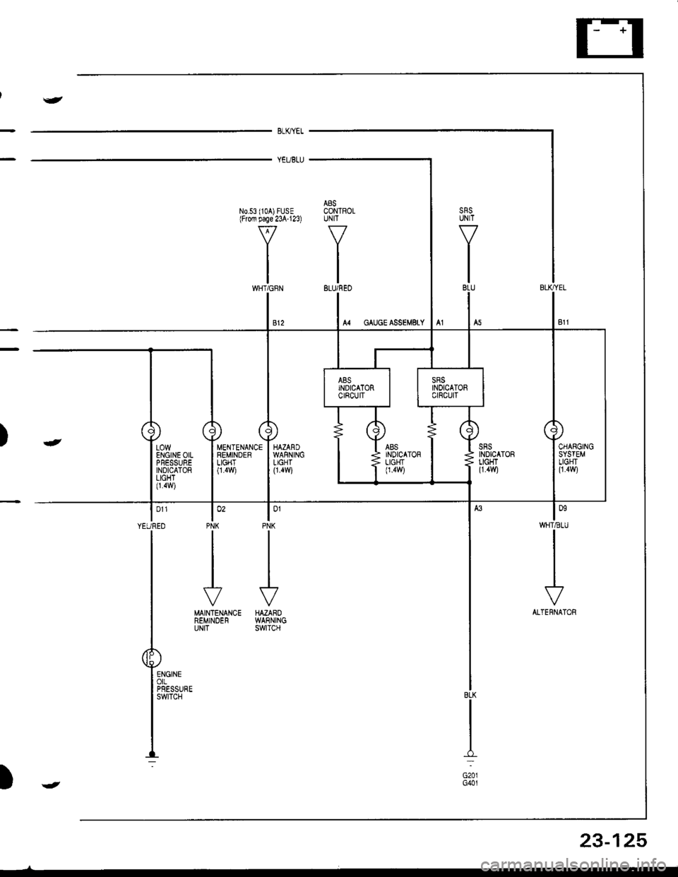
J
BLKYEL
YEUBLU
A8SN0.53 (104) FUSE CONTROLlFrofi page 23A'123) UNIT
VV
II
tltlWHT/GFN BLU/REO
lonWHT€IU
I
I
I
\?
ALTERNATOR
lo'PNK
J
HAZAROWARNINGswtTcH
MENTENANCEREMINDERLIGHT0.4v,/i
lo'PNK
II
I
J
MAINTENANCEREMINDERUNIT
| 011
YEUREO
I
T
P"-:
)-
BLK
I:
G201G401
LOWENGINE OILPFESSUREINDICATORLIGHT0.4w)
23-125
)J
Page 1190 of 1681
I
Seat Belt Reminder
SystemLow Fuel lndicator
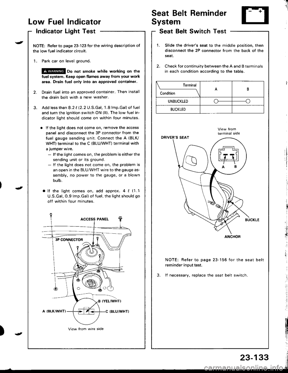
Indicator Light Test
NOTE: Refer to page 23-123 for the wiring description of
the low fuel indicator circuit.
1. Park car on level ground.
@ oo not smoke whilc wolking on the
fuel system. Keep open tlames away from your work
area. Drain fuel only into an approved container.
2. Drain fuel into an approved container. Then install
the drain bolt with a new washer.
3. Add lessthan 8.2 t l2.2U.S.Gal, 1.8 lmp.Gal)of fuel
and turn the ignition switch ON {ll). The low fuel in-
dicator light should come on within lour minutes.
. lf the light does not come on. remove the access
panel and disconnect the 3P connector from the
fuel gauge sending unit. Connect the A (BLV
WHT) terminal to the C (BLU,/WHT) terminal with
a jumper wire.
- lf the Iight comes on, the problem is either the
sending unit or its ground.- lf the light does not come on, the problem is
an open in the BLU/WHT wire to the gauge as-
sembly, no power to the gauge, or a blown
bulb.
a lf the light comes on, add approx.4 ! (1.1
U.S.Gal. O.9 lmp.Gal) of fuel, the light should go
off within four minutes.
I
i
)
SeatSwitchTestBelt
1.Slide the driver's seat to the middle position. then
disconnect the 2P connector from the back of the
seat.
Check tor continuity between the A and B terminals
in each condition according to the table.
NOTE: Refer to page 23-156 for the seat belt
reminder input test,
3. lf necessary, replace the seat belt switch.
Terminal
c""dil----lB
UNBUCKLEDoo
BUCKLED
ANCHOR3P CONNECTOR
23-133
Page 1192 of 1681
Brake System Indicator
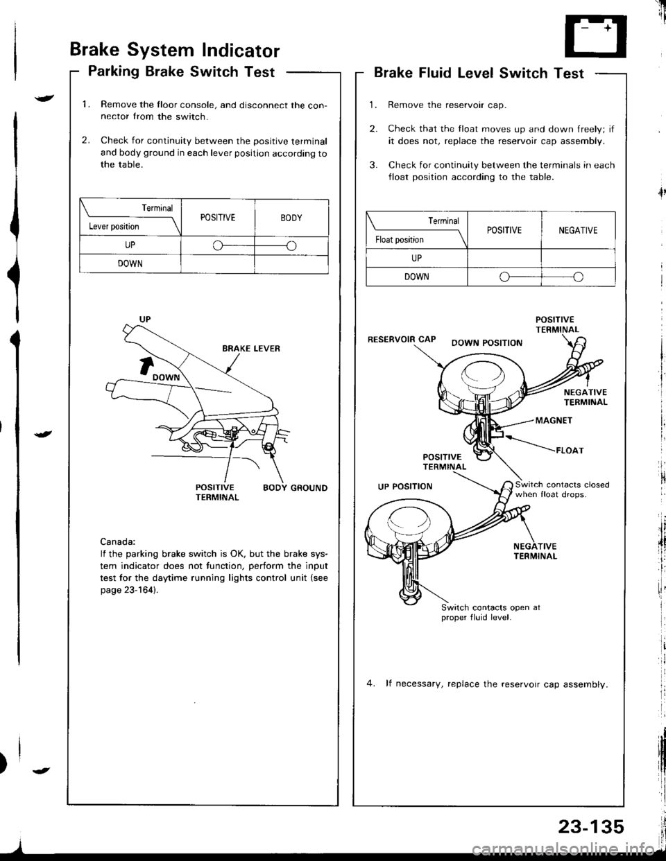
Parking Brake Switch Test
1.Remove the Iloor console, and disconnect the con-nector from the switch.
Check for continuity between the positive terminal
and body ground in each lever position according tothe table.
2.
POSITIVE BODY GROUNDTERMINAL
Canada:
lf the parking brake switch is OK, but the brake sys-
tem indicator does not function, perform the input
test for the daytime running lights control unit {see
page 23-164).
Terminal
l"*rr*ril---ltPOSITIVEBODY
UPoo
DOWN
'il
--r '1i
T- +T
L.J
Brake Fluid LevelSwitch Test
Remove the reservoir cap.
Check that the float moves up and down freely; if
it does not, replace the reservoir cap assembly.
Check for continuity between the terminals in each
lloat position according to the table.
POStnVETERMINALRESERVOIR CAPDOWN POSITION
4l
NEGATIVETERMINAL
MAGNET
POSITTVETERMINAL
*----raoo,
Switch contacrs closedwhen float drops.UP POSITION
TIVETERMINAL
Switch contacts open atproper fluid level.
4. lf necessary, replace the reservoir cap assemblv.
| ermrnal
Float position \POSITIVENEGATIVE
UP
DOWNo--o
I
Page 1197 of 1681
![HONDA INTEGRA 1998 4.G Manual PDF A/T Gear Position Indicator
Component Location Index
GAUGE ASSEMALYRemoval, page 23-126Disassembly, page 23-127Bulb Locations, page 23-122INTERLOCK SYSTEMDescription, page 23-147A/T GEAR POS]TIONINDI HONDA INTEGRA 1998 4.G Manual PDF A/T Gear Position Indicator
Component Location Index
GAUGE ASSEMALYRemoval, page 23-126Disassembly, page 23-127Bulb Locations, page 23-122INTERLOCK SYSTEMDescription, page 23-147A/T GEAR POS]TIONINDI](/img/13/6069/w960_6069-1196.png)
A/T Gear Position Indicator
Component Location Index
GAUGE ASSEMALYRemoval, page 23-126Disassembly, page 23-127Bulb Locations, page 23-122INTERLOCK SYSTEMDescription, page 23-'147A/T GEAR POS]TIONINDICATORInput Test, page 23-142
A/T GEAR POSTTION SWITCHTest, page 23-144R6olacement, section 14
:S
23-140
Page 1199 of 1681
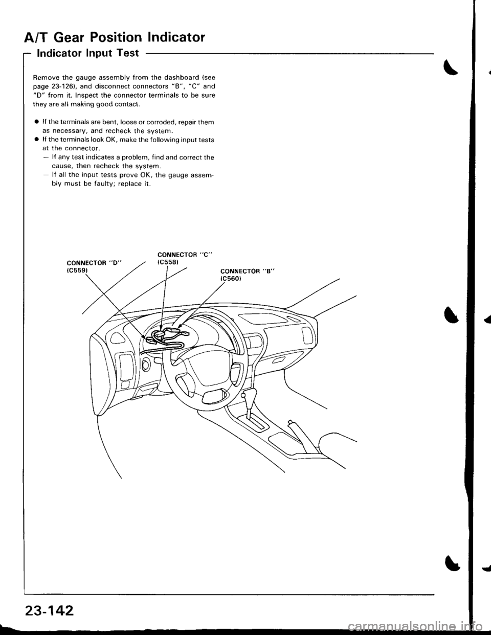
A/T Gear Position Indicator
Indicator Input Test
Remove the gauge assembly from the dashboard (see
page 23-1261, and disconnect connectors "8", "C" and"D" from it. Inspect the connector terminals to be sure
they are all making good contact.
a lI the terminals are bent, loose or corroded, repair them
as necessary, and recheck the system.a lI the terminals look OK, make the following input tests
at the connector.- l{ any test indicates a problem, find and correct the
cause, then recheck the system.
lf all the input tests prove OK, the gauge assem-
bly must be faulty; replace it.
CONNECTOR "B"
=------'\-\-\\---- =
23-142
Page 1201 of 1681
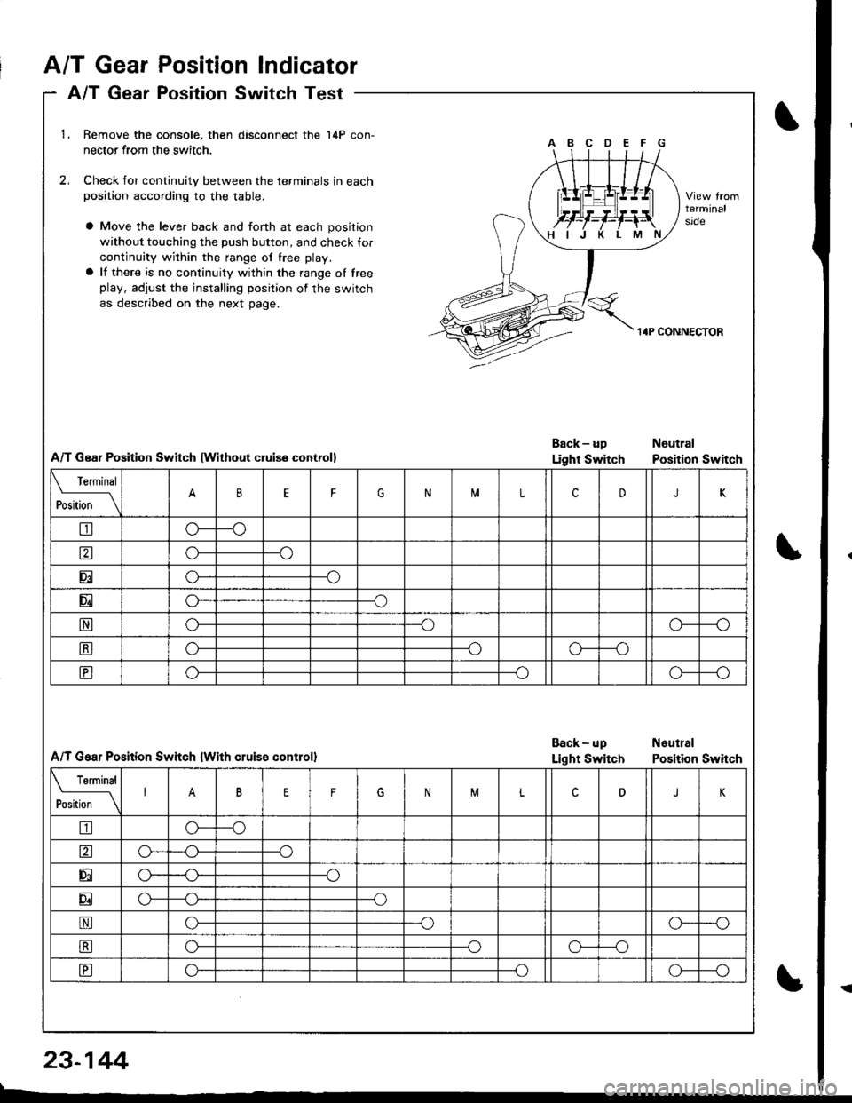
1.Remove the console, then disconnect the 14P con-
nector from the switch.
Check for continuity between the terminals in eachposition according to the table.
2.
Move the lever back and forth at each position
without touching the push button, and check fof
continuity within the range of free play.
lf there is no continuity within the range of freeplay, adjust the installing position of the switch
as described on the next page.
terminalsroe
A/T Geal Position Switch lwithout cluise control)
Back-uD Noutral
Light Switch Position Switch
A/T G€ar Position Switch lwith cluise controll
Back - up Neutlal
Light Switch Position Switch
Terminal
P*m""
_\BFGNiTLcDJK
tro---o
ao---o
Eo---o
Eo---o
No--_o--o
tro---oo---o
Eo--_oo---o
rermrnal
t]"t-
_\BEFGNMLcDJ
tro----o
o---o
EG_--o
Eo---o
No---oo---o
tro--oo---o
EG---oo---o
A/T GearPosition Indicator
A/T GearPosition Switch Test
23-144
I
Page 1209 of 1681
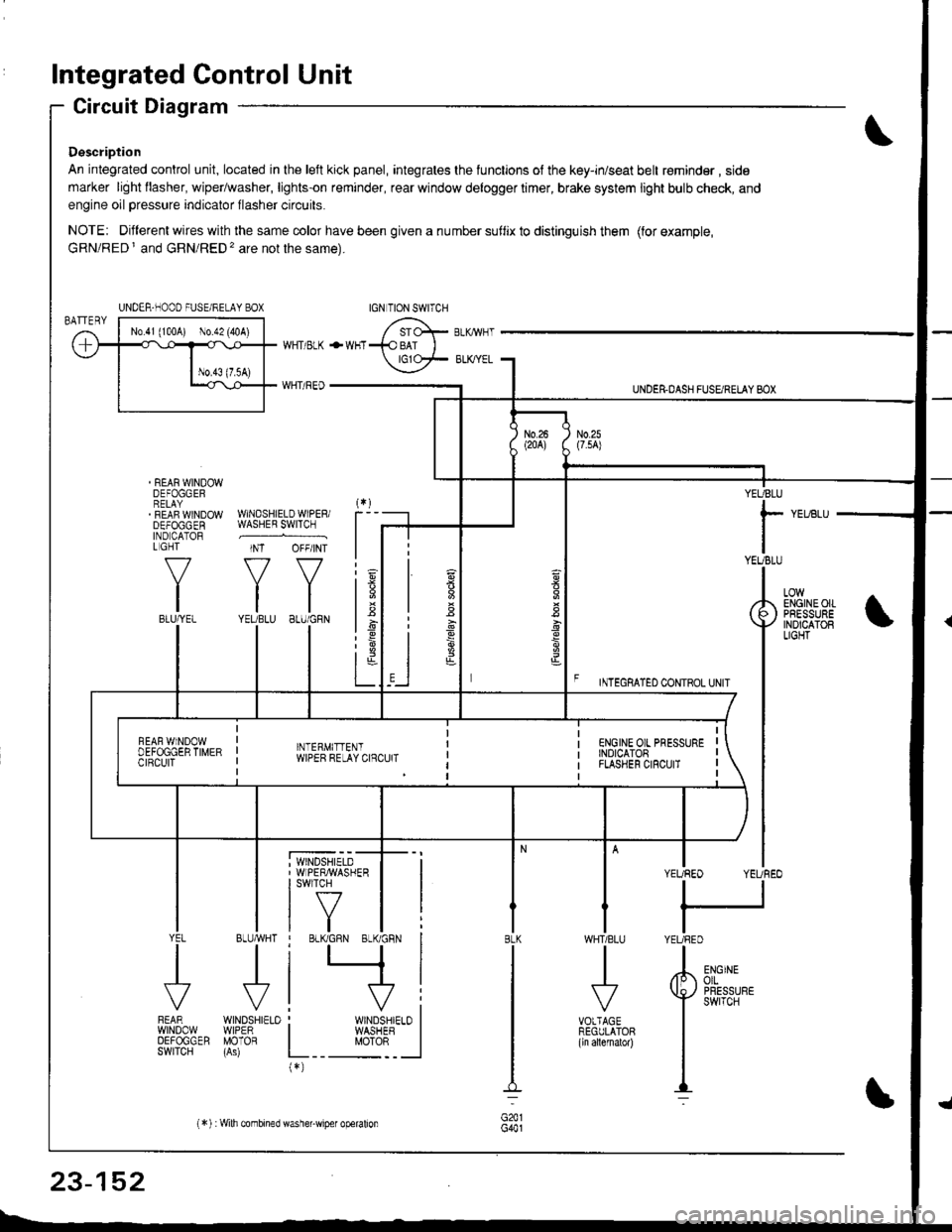
Integrated Control Unit
Circuit Diagram
Description
An integrated control unit, located in lhe left kick panel, integrates the lunctions of the key-in/seat belt r€minder , side
marker light llasher, wiper/washer, lights-on reminder, rear window delogger timer, brake system light bulb check, and
engine oil pressure indicator flasher circuits.
NOTE: Different wires with the same color have been given a nu mber suflix to distinguish them (for example,
GRN/RED I and GRN/RED'� are not the same).
REAR WINDOWDEFOGGERRELAYREAF WINDOWDEFOGGENIND CATORL GHT
f-7
IIBLU/YEL
WHT/ BLK
WHT/ REO
+WHT
WNDSHIELDWIPERiWASHER SWITCH
INT OFF/INT
f7 f7
tltlYEUBLU 8LU/GRN
BLUMHT
J
wtN0sHr€10WIPERMOTOR
UNDER.DASH FUSARETAY BOX
F rmecnlleo counoL ultr
YEUBLU
rYEUBLU
YEUREO YEUREO
tl
IYEURED
LOWENGINEOIIPRESSUREINOICATOBLIGHT
; WINDSHIELD' WIPERMASHERI swlTcH
tf7IVtlYEL
J
FEARwtN00wOEFOGGERSWITCH
WHTIBLU
J
VOTTAGEREGULATOR(ln allernatol)
BLK
G441
ENGINEolLPRESSUREswrTcH
UNDER-NOOO FUSE/RELAY BOX
1.6
:6
t;t-L
i
"'i'- 'i*-
|
I Il
I vi: WINDSHIELO II WASHEB I
L__ "oto: _ __l(*)
n
s
s
,]
23-152
(*) :Wilh combined washer-wiper operalion
Page 1213 of 1681
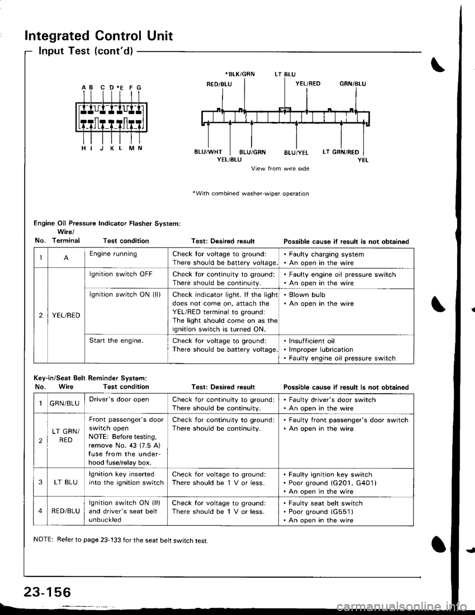
Integrated Control Unit
lnput Test (cont'd)
YEL/BLU
View from wire side
'With combined washer-wiper operation
Engine Oil Pressure Indicator Flasher System:
Wire/
No. TerminalTest condition
Key-in/Seat Belt Reminder System:
No. WileTest condition
Testi Desired result
Test: Desired result
Possible cause if result is not obtainsd
Possible cause if fesult is not obtained
*BLK/GRN
1Engine runningCheck for voltage to ground:
There should be battery voltage.
. Faulty charging system. An open in the wire
2YEL/RED
lgnition switch OFFCheck for continuity to ground:
There should be continuity.
. Faulty engine oil pressure switch. An open in the wire
lgnition switch ON (ll)Check indicator light. It the light
does not come on, attach the
YEL/RED terminal to groundl
The light should come on as the
ignition switch is turned ON.
. Blown bulb. An open in the wire
Start the engine.Check tor voltage to ground:
There should be battery voltage
lnsufticient oil
lmproper lubrication
Faulty engine oil pressure switch
1GRN/BLUDriver's door openCheck for continuity to ground:
There should be continuity.
. Faulty driver's door switch. An open in the wire
2
LT GRN/
RED
Front passenger's door
swrlcn open
NOTE: Before testing,
remove No. 43 {7.5 A)
fuse from the under-
hood fuse/relay box.
Check for continuity to ground:
There should be continuity.
. Faulty front passenger's door switch'An open in the wire
3LT BLU
lgnition key inserted
into the ignition switch
Check for voltage to ground:
There should be 1 V or less.
Faulty ignition key switch
Poor ground (G2O1, G401 l
An open in the wire
4RED/BLU
lgnition switch ON (lll
and driver's seat belt
unbuckled
Check for voltage to ground:
There should be 1 V or less.
Faulty seat belt switch
Poor ground (G551l
An open in the wire
NOTE: Refer to page 23-133 for the seat belt switch test.
Page 1216 of 1681
)
Engine Oil Pressure
Indicator System
Description
NOTE: Refer to page 23-152 for the circuit diagram ofthe engine oil pressure indicator flasher. and to page 23
156 for the input test of the flasher circuit.
The low engine oil pressure indicator light works in twoways. lt will flash continuously following a momentaryloss ol oil pressure, or it will go on and stay on wath a
complete loss of oil pressure.
When the engine first starts, before oil pressure rises
above 29.4 kPa (O.3 kgf/cmr, 4.3 psi), current flows
through the low engine oil pressure indicator light andthe oil pressure switch to ground. This tests the circuit.
With the engine running, voltage is applied to the Ilash-er circuit of the integrated control unit. With normal oilpressure, the oil pressure switch is open and the low en-gine oil pressure indicator light does not operate. lf the
oil pressure switch closes momentarily (more than O.5
seconds). but then opens again, terminal "YEL/RED" will
sense ground through the switch- The integrated con-trol unit will then provide and remove ground tor the low
engine oil pressure indicator light through terminal"YEL/RED". The light will flash on and off untilthe igni
tion switch is turned to "OFF".
lf engine oil pressure talls below 29.4 kPa (O.3 kgf/cmr,
4.3 psi) and does not increase, the oil pressure switchwill stay closed. The low engine oil pressure indicator light
will go on and stay on.
NOTE: Refer to page 23-130 for the engine oil pressure
switch test.
I
23-159