indicator HONDA INTEGRA 1998 4.G Workshop Manual
[x] Cancel search | Manufacturer: HONDA, Model Year: 1998, Model line: INTEGRA, Model: HONDA INTEGRA 1998 4.GPages: 1681, PDF Size: 54.22 MB
Page 1347 of 1681
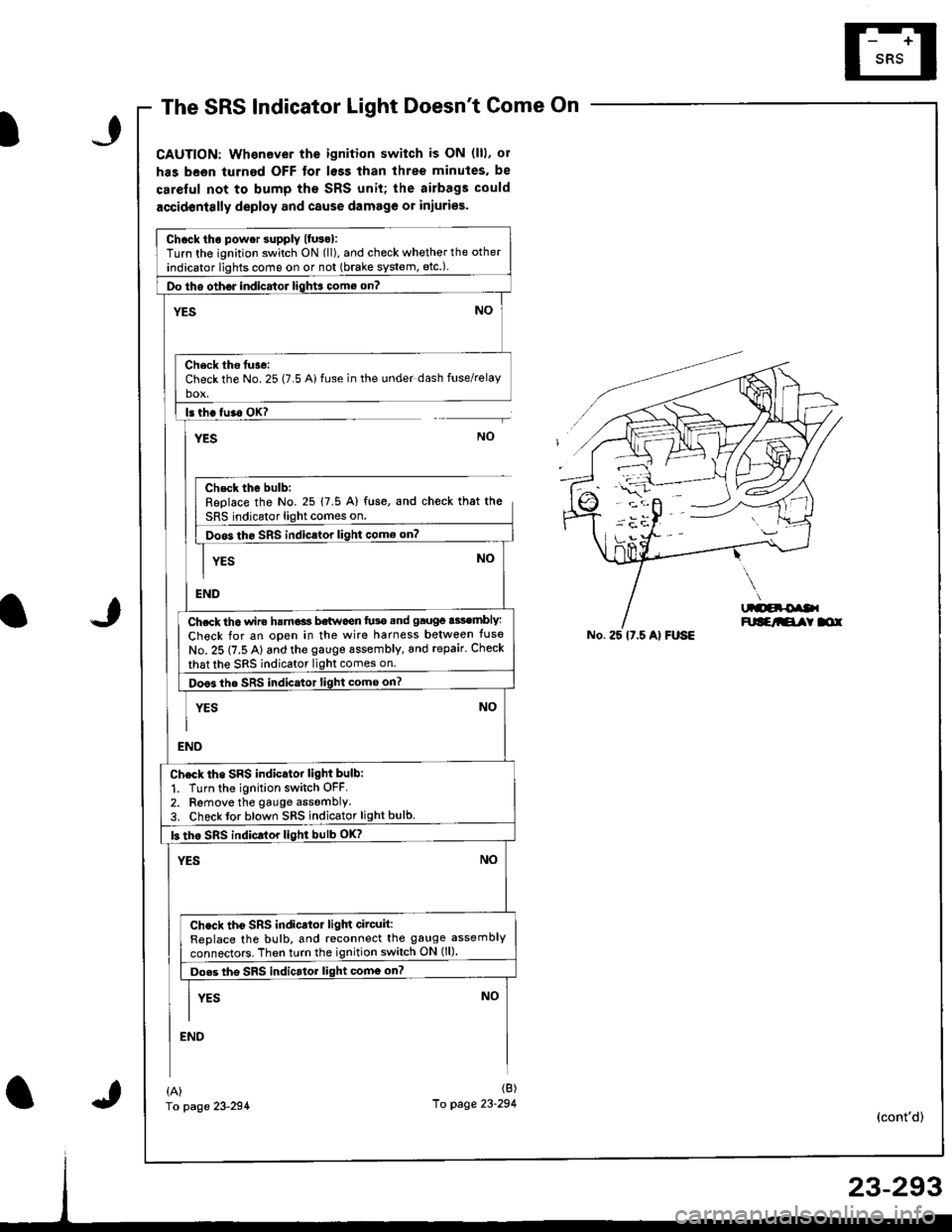
The SRS Indicator Light Doesnt Come On
CAUTION: Whenever the ignition switch is ON (lll, ol
has been turned OFF tor lsss than three minutes. be
careful not to bump the SRS unit; the airbags could
accidentslly deploy and cause damage or iniuries.
Chcck tho power supply lfuso):Turn the ignition switch ON (ll), and check whether the other
indicator lights come on or not (brake system, etc.).
Do tho oth6J indicator ligh$ come on?
NO'ES
Check ths tuse:Check the No. 25 (7.5 Ai fuse in the under dash fuse/relayho!
ls th. tu.o OK?
YESNO
Chsck the bulb:Replace the No. 25 17.5 A) fuse, and check that the
SRS indicator light comes on.
Doos tho SRS indic.lor light como on?
YES
END
Ch.ck th6 wir€ ham€ls b€twoen fu3e snd gauge .3sembly:
Check for an open in the wire harness belween tuse
No. 25 (7.5 A) and the gauge sssembly, and repair. Check
that the sRS indicator light comes on.
Doo3 the SRS indicator light come on?
YES
NO
NO
END
Ch6ck tho SRS indicator light bulb:
1. Turn the ignition switch OFF.2. Remove the gauge assemblY3. Check tor blown SRS indicator light bulb.
b tho sRs indicrlor light bulb oK?
YESNO
Check tho SRS indicator ligln circuit:ReDlace the bulb, and reconnect the gauge assembly
connectors. Then turn the ignition switch ON (ll).
Do.s tho SRS indicrtor light comG on?
I vrs NoII
END
No. 25 lt.5 Al FUSE
{A)fo page 23-294
(B)
10 page 23-294(cont'd)
Page 1348 of 1681
Troubleshooting
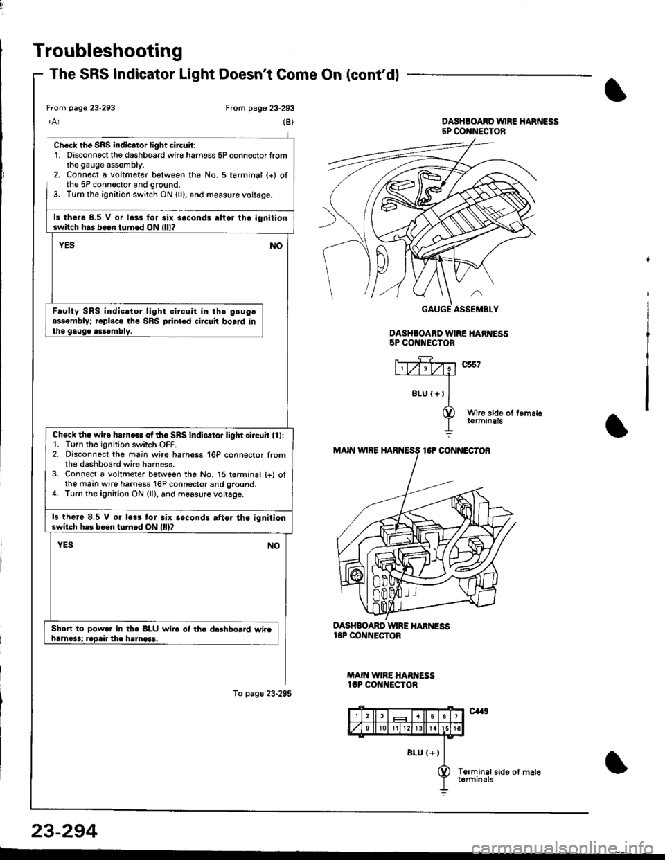
The SRS Indicator Light Doesnt Come On (cont'd)
From page 23-293
(B)
Ch.cl th. SRS indicator light circuit:1. Disconnect the dashboard wire harness 5P connector fromthe gauge assembly.2. Connect a voltmeter belween the No. 5 terminal (+) ofthe 5P connoctor and ground.3. Turn the ignition switch ON {ll}, and measure voltage.
ls the.e 8.5 V or less for six 3econd! rflor lho ignitionswitch h.s be6n turned ON llll?
YESNO
Faulty SRS indicstor light circuit in ihe gtugoassembly; r€pl.co tho SRS printed circuit board inthe gaug. assembly.
Check the wiro ham.ss of tho SRS indicltor light circuh ll l:1. Turn the ignition switch OFF.2. Disconnect the main wire harn€ss 16P connector lromthe dashboard wire harness.3. Connect a voltmeter betlveen the No. 15 torminal {+) ofthe main wire harness 16P connector and ground.4. Turn the ignition ON (ll), and measure voltage.
13 there 8,5 V or lc.r tor 3lx s.condr lftor th. ignitionswitch h.3 boon tuJnod ON llll?
Short to powor In th. BLU wiro ot ths d$hbolrd whahrmess; ropair the hsmo*1.
To pag€ 23-295
DASHBOARD WINE HAR ESS16P CONNECTOR
MAIN WIRE HARI{ESS16P CONNECTOR
From page 23-293
DASHBOAND VUIRC HARNESS5P CONNECTOB
DASHBOARD WIRE HARI{ESS5P CONNECTOR
23-294
Page 1350 of 1681
Troubleshooting
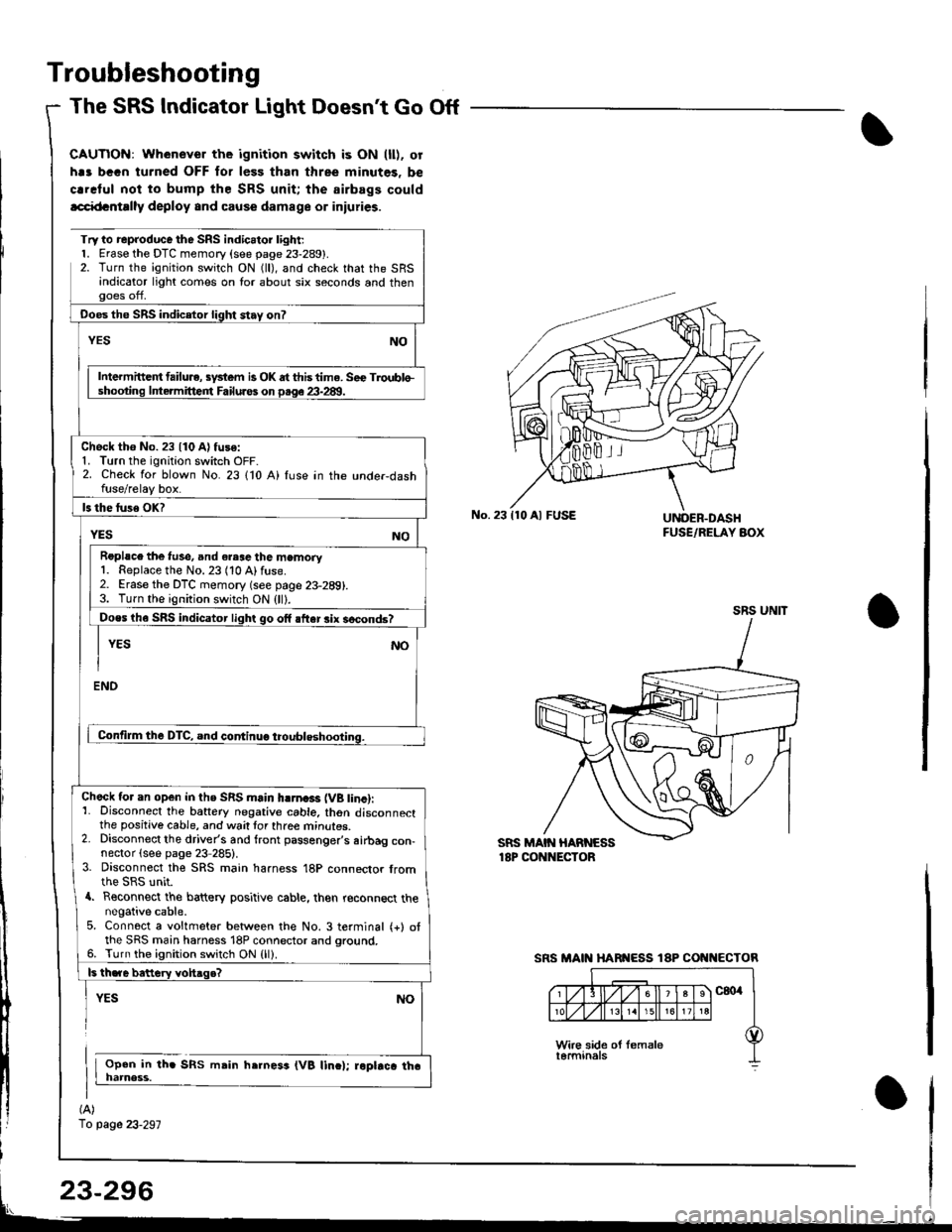
The SRS Indicator Light Doesnt Go Off
CAUTIOi{: Whenever the ignition switch is ON (ll). or
h.s bGGn turned OFF for less than three minutes. be
crrclul noi to bump the SRS unit; the airbags could
lcci{tcntrlly deploy and cause damage or iniuries.
(A)
1o page 23-297
Try to reproduce the SRS indic.tor l;ght;l. Erase the DTC memory (see page 23-289).2. Turn the ignition switch ON (ll), and check that the SRSandicator light comes on lor about six seconds and thenooes off,
Ooes the SRS indicetor light stay on?
NOYES
Intermittc t failu.e, sydem is OK dt this time. Sec Troublo-shooting lntermitteirt Failuros on p.qe 23-28!1.
Check tho No. 23 {10 A) fuse:1. Turn the ignition switch OFF-2. Check for blown No. 23 110 A) fuse in the unde.dashfuse/relay box.
ls the luse OK?
YESNO
Roplsce the f!se, and eresc the memory1. Replace the No. 23 (10 Alfuse.2. Erase the DTC memory (see page 23-289).3. Turn the ignition switch ON (ll).
Does th6 SRS indicator light go off after rix socond6?
I YEs No
I
ENO
Contilm the DTC, and continuo troubleshooting.
Check tor an open in ths SRS main hlrna3r (VB tinc):1- Disconnect the battery negative cable. thon disconnectthe positive cable, and wait tor three mrnures.2. Disconnect the driver's and front passenger's airbag con-nector (see page 23 285).3. Disconnect the SRS main harness 18P connector fromthe SRS unit.a. Reconnect the battery positive cable, then reconnect thenegative cable.5. Connect a voltmeter between the No. 3 terminal (+) otthe SRS main harness 18P connector and ground.6. Turn the ignition switch ON {ll).
ls th.re bettery vohaqe?
YES
Open in th. SRS msin h.rness (VB linc); roptrca tha
NO
No.23110 Al FUSEUNOER.DASHFUSE/RELAY AOX
SRS UNIT
SRS MAIN HARI{ESS 18P COI{I{ECTOR
Page 1351 of 1681
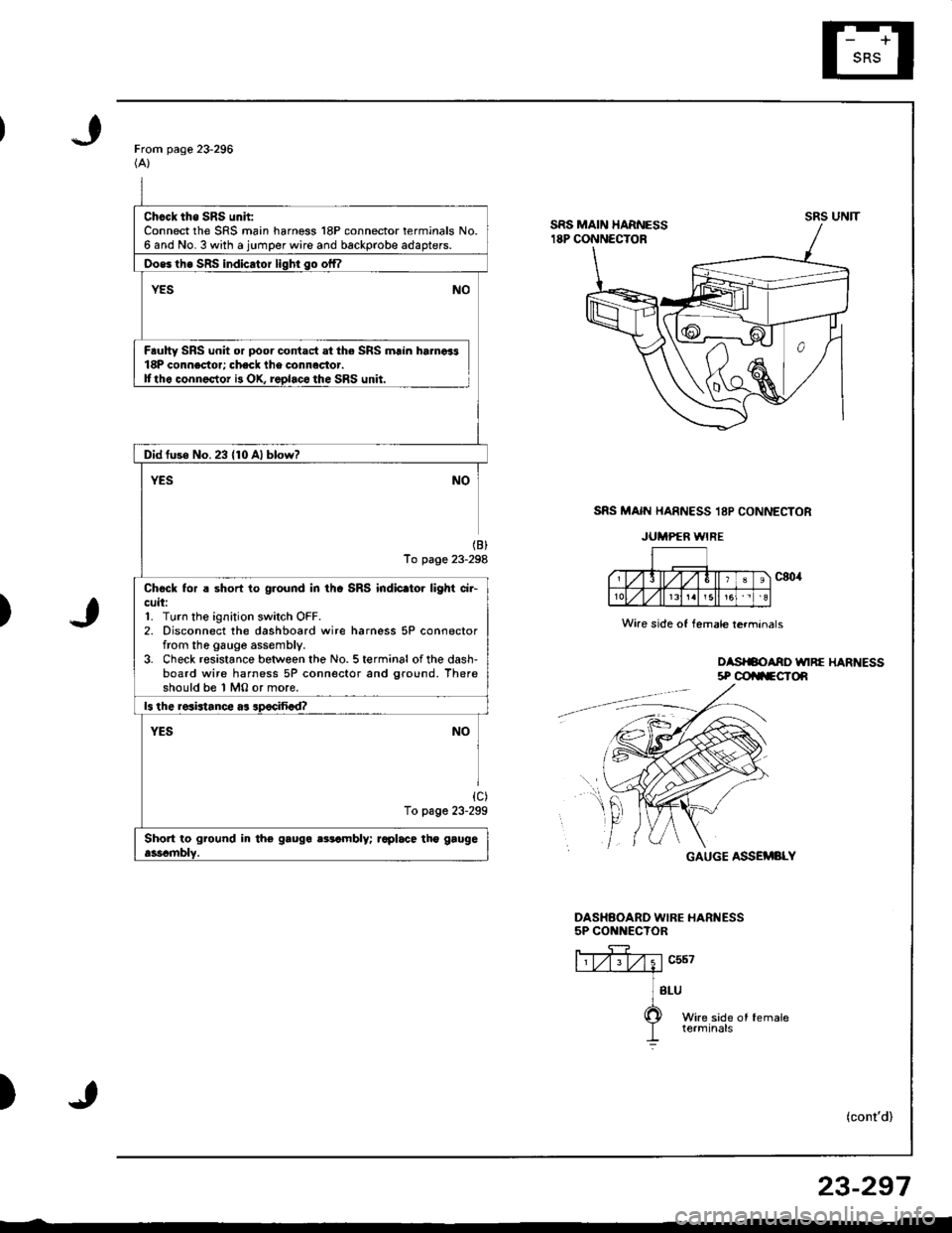
Chcck tho SRS unh:Connect the SRS main harness 18P connector terminals No.6 and No. 3 with a jumper wire and backprobe adapters.
Oos6 th6 SRS indicator liqhi so offl
YESNO
Faulty SRS unit or poor contact at the SRS main hamoi318P connector; check lhe connactor.Ittho connector i3 OX, replaco the SRS unit.
Did fuse No.23 {10 Al blow?
YESNO
(B)
To page 23-298
Chock tor a short to ground in thc SRS indic.tor light ci.-cuit:1. Turn the ignition switch OFF.2. Disconnect the dashboard wire harness 5P connectorfrom the gauge assembly.3. Check resistance between the No. 5 terminal of the dash-board wire harness 5P connector and ground. Thereshould be 1 MO or more.
ls the resistance as apocifiad?
YESNO
{c)To page 23-299
Short to ground in tho gauga aatambly; raplace tho gaugeasscmblY.
From page 23-296(A)
SRS MAIN HARNESS 18P CONNECTOR
JUMPER WIRE
)
oasrSoAno unRE HARt{Ess5P @ilFCTOn
GAUGE ASSEMBLY
DASHAOARD WIBE HARNESS5P CONNECTOR
ffiv;1"u*---.--a
] sru
O wire side of female
I terminals
)(cont'd)
UNITsRs
Wire side of female lerminals
f,t
r
23-297
Page 1352 of 1681
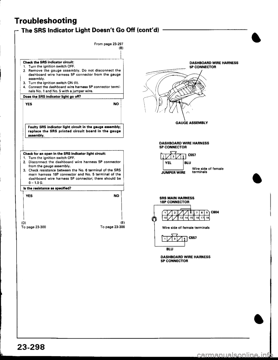
Troubleshooting
The SRS Indicator Light Doesn't Go Off (cont'd)
From pags 23-297(8)
ch.ct tha SRS indicrtor circuit:1. Turn tho ignition switch OFF.2- Remove the gauge assembly. Do not disconnoct thedashboard wire harnosg 5P connector from the gaugg
assemblY.3. Turn the ignitjon switch ON {ll).4. Connect the dashboard wire hrrng6a 5P connector torminals No. I and No.5 with a iumoerwire.
Doe3 th. SRS indicator lisht go otf|
NOYES
Faulty SRS indic.tor light circuh in th. g.ug. r*t mbly;raplroe th. SRS prini.d ciJcuit bolrd in th. g.ug.
9$emblY.
ch.ck loi .n op.n in th. SRS indicltor ligl|t circuh:1. Turn the ignition switch OFF,2, Disconn€ct the dashboard wire harnoss 5P connectorfrom th6 gauge assembly.3. Check resistanco between ths No. 6 t€rminal ot the SRSmain harneas 18P conngctor and No. 5 terminal of th6dashboard wire harness 5P connector; there should bs0-1.00.
lr tha raaidanca aa lpacifiad?
YESNO
(D)
To page 23-300
(E)
To page 23-300
DASHBOARD WIRE HARNESS5P COt{t{ECTOR
SRS MAIT{ HARNESSt8P CON ECTOR
OASHBOARD WIRE HARI{ESS5P COI{NECTOR
OASHBOABD WIRE HARNESS5P CONNECTOR
rt#z;trxistL,iry
lYEr lBruWir6 sido oI fomaleJUMPER W|RE terminals
GAUGE ASSEMBLY
W 6 side of lemale terminals
23-298
Page 1354 of 1681
Troubleshooting
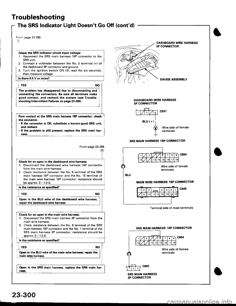
The SRS Indicator Light Doesn't Go Off (cont'dl
23-300
t
Fro- !'age 23'298lDASHBOARD WIRE HARNESS5P CONNECTOR
Ch.ct rh. SRS indicator circuh input vohagei1. Reconnect the SRS main harness 18P connector to theSRS unit.2. Connoct a voltmeter between the No. 5 terminal (+) ofthe dashboard 5P connector and oround.3. Turn the ignition switch ON lll), wait tor six seconds,then measure
GAUGE ASSEMBLY
DASHBOARO WIRE HARNESS5P CONl{ECTOR
c557
Wire side ol femaletermrnals
SRS MAI[{ HARNESS 18P COI{I{ECTOR
From page 23-298(E)
SRS MAII HARI{ESS 18P CONNECTOR
SRS MAIN XARI{ESS3P CONNECTOR
f'l! thor6 8.5 V o. mo.e?
Tho problom has disappearod due to disc_onnscting andconnacting tha connectols. Be sure all torminal3 makegood contact, and rechock the sy3tom lsaa Trouble-shooting Intormittont Failurss on pago 23-289).
Poor contact at tho SRS main hamess 18P conncctor; chatclthe conn6c'toa.. lf the connocto. is OK, substitute a known-good SRS unit,and rechock.' It the problom is still prescnt, r.phca the SRS main har-noas.
MAI WIRE HARNESS lGP CONNECTOR
Terminalsid€ ol male terminals
Chock tor an ooen in the dashboard wire haino*!:1. Disconnect the dashboard wire harness 16P connectorfrom the main wire harness.2- Check resistance between the No.6 terminal ofthe SRSmain harness 18P connector and the No. 15 terminal olthe main wire harness 16P connector; resistance shouldbe aDorox. 0 - 1.0 0.
ls th. resistanco a3 spacifigd?
Open in th. BLU wir6 of the drshborrd wirc harnsss;
Chock for an op6n in tha main wire harn6$:1. Disconnect the SRS main harness 3P connector from themain wire harness.2. Check resistance between the No. 6 terminal of the SRSmain harness 18P connector and the No. 1 terminal of theSRS main harness 3P connector; resistance should boaoorox.0-1.0O.
13 th6 r6ktanca as 3pocifiod?
Open in the SRS main ha.n$s; roplac. tha SRS main hsr-nai!i.
Open in the BLU wir. oltha mrin wirc harna.s; r.pair themain wiao hamoss.
Page 1355 of 1681
)
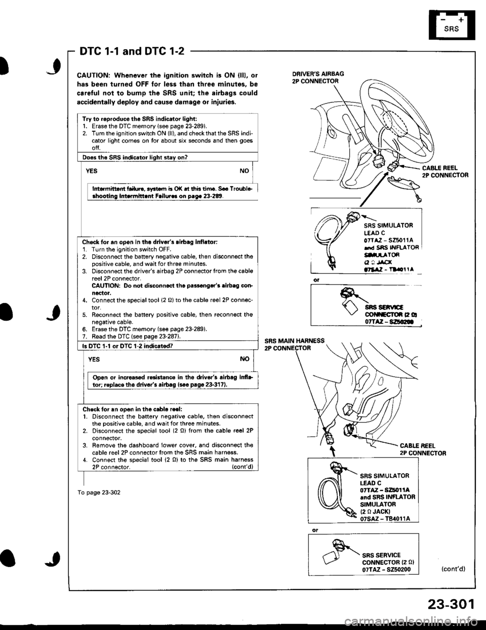
DTC 1-1 and DTC 1-2
CAUTION: Whenever the ignition switch is ON {lll, or
has been turned OFF for less thsn three minutes, be
ca.eful not to bump the SRS unit; the airbags could
accidentally deploy and cause damage or iniuries.
CABLE REEL2P CONNECTOR
SRS SIMULATORL€AD CoTtaz - s6011Alrd Sns IYFLATORg.prToR
o ! Jrcxatllil - n olrl
*.t sns savE\,' colltcroe c o07TAZ-8E@
CABLE BEEL2P CONNECTOR
SRS SERVICEGoNNECTOR (2 0l
07TAZ - 5250200(cont'd)
Try to roproduce the SRS indicator light:1. Erase the DTC memory lsee page 23-289).2. Turn the ignition switch ON (ll), and check that the SRS indicator light comes on tor about six seconds and then goes
ofJ.
Do€s the SRS indicator light stay on?
YES
h6rmittar'rt Lalul!, 3yrtdll b o|( rt thb tiiru. 5€6 lroubl6-ahootino lmarmitlant Failura. on o.oa 23-289.
Chock fo. an opGn in the dlivgl's cirbag infirtor:'1. Turn the ignition switch OFF.2. Disconnect the battery negative cable, then disconnect thepositive cable, and wail for thrce minutes.3. Disconnect the driver's airbag 2P connectorlrom th€ cablereel 2P connector-CAUTION: Do not disconnoct tho palF€nger'r .ilb.g con-nector.4. Connect the sDecial tool 12 o) to the cable reel 2P connec-tor.5. Reconnect the bsftery positive cable, then reconn€ct thonegative cable.6. Erase the DTC memory (se€ page 23-289).7. Bead the DTC (see page 23-2811.
ls DTC 1-1 oI DTC 1-2 indic.tod?
YESNO
Opon or incro8od r.rist.nco in tho driv6.'3 airbag inf+
lor; replacs tho drivor'3 rirb.g lsoe prgg 23-317).
Ch.ck for an op6n in the cablo re.l:1. Disconnect the battery negativo cabl6, thon disconnectthe positive cable, and wait for three minutes.2. Disconnect the soecial tool (2 o) from rhe cable reel 2Pconnector.3. Remove the dashboard lower cover. and disconnoct thecable reel2P connectorfrom the SRS main harness.4. Connect tho special tool (2 0) to thg SRS main harness2P connector. (cont'dl
To page 23-302
SRS SIMULATOR|.EAO C07TAZ - Si4tor lAand SRS INFLATORSIMULATOR(2 0 JACK)
23-301
Page 1357 of 1681

DTC 1-3
)
CAUTION: When€ver the ignition 3witch is ON (ll), or
has been turned OFF for le3s lhan three minute3, be
careful not to bump the SRS unit; the airbags could
accidontally d€ploy and cause damage or iniuries.
Chcck for a short to anothor wiro in the driver's airbag inlla-tor:1. Turn the ignition switch OFF.2. Disconnect the battery negative cable, then disconnectthe positive cable, and wait tor three minutes.3. Disconnect the driver's airbag 2P connector from thecable reel 2P connector.CAUTION: Do not diaconnocl the p.sseng.r'5 !irbaOconnoctor.4. Connect the special tool {2 o} to the cable reel 2P connec'tor,5. Reconnect the battery positive cable, then reconnect thenegative cable.
SRS SIMULATORLEAD C0?TAZ - SZ5011Aand SRS INFLATORSIMULATORt2 0 JACKI07SAZ - T8,(}11A
)
Erase the DTC memory (see page 23-2891.Road the DTC (see page 23-287).
o1
,"" rr*u,".GoNNECTOR 12 0)
07TAZ - S250200(cont'd)
SRS SIMULATORI.EAD CorTAZ - SZ5011A.nd SRS INFLATORSIMULATOR12 0 JACKI07SAZ-TBrl011A
TrVto reproduce the SRS indicator light:1. Erase the DTC memory (see page 23-289).2. Turn the ignition switch ON (ll), and checkthatthe SRS indicator light comes on for about six seconds and then goesoff.
Doss tho SRS indicato. liqht stav on?
Intormittent failure, 3yitom i3 OK at thk timo. S€a TrouH€-
Short in tho drivar's sirblg inflstor; replace the driv-
Chock for s shon in tho cablo rool:'1. Disconnect the battery negative cable, then disconnectthe positive cable, and wait tor three minutes.2. Disconnect the special tool (2 0) from the cable re€l 2Pconnector,3. Remove the dashboard lower cover, and disconnect lhecable reel 2P connector from the SRS main harness.4. Connect the special tool (2 O) to the SRS main harness
To page 23-304
)
23-303
Page 1359 of 1681
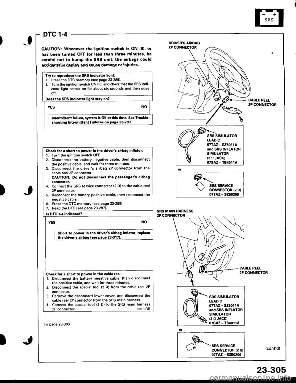
DTC 1-4
GAUTION: Whenever the ignition ewitch i! ON (ll), or
has been turned OFF tor l€ss than ihre€ minutes, be
caroful not to bump the SRS unit; tho airbag3 could
accidrnta[y deploy and caus€ damage or iniuries.
9--'-.- sns sERvrcE\,/ cli|f\FgfoR {2 ol07TAZ - SZqI200
ol
SRS SERVICEcot{ltEcToR {2 0}07TAZ - S:Zso2qt
CABLE REEL2P CONNECTOR
(cont'd)
Try to r.p.oduco tho SRS indicator light:1. Erase the DTC memory (see page 23-289).2. Turn the ignition switch ON (ll), and check that the SRS indi-
cator light comes on lor about six seconds and then goes
off.
Doo3tho SBS indic.tor light stry on?
YESNO
lnt rmittont tsiluio, systom i! (X tt thb timc. Soo Troublc
shooting Inte.mittani Failutca on P.g. 23-289.
Chock tor a shortto power in tha drivo/! ritbag inflllor:
l. Turn the ignition switch OFF.2. Disconnect the battery negativ€ cable, then disconnsct
th6 oositive cable, and wait for three minutes.
3. Disconn€ct the driver's airbtg 2P connector from the
cable reel 2P conn6ctor.CAUTION: Do not disconnost tha p!r3ong.t's rirbag
connoclor.4. Connect the SRS service connector (2 O) to the cable reel
2P connector,5. Reconnect the battery positive cable, then reconnect thenegative cabl€.6. Erase the DTC memory lsee page 23-289).7. Read the DTC (see gage 23-2aiL
|3 DTC 1-4 indicrtod?
YESNO
Shon to powa. in tha d val's tiabag itlflltor; iopl.cathe ddv.r'. airbag {t€c prge 23-317).
Check for ! short to pow.r in the cabls.oali1. Disconnect the battery negative cable. then disconnectthe positive cable, and wait for three minutes.2. Disconnect th€ special tool (2 o) from the cable reel 2P
conneclor.3. Remove the dashboard lower cover, and disconnect the
cable reel 2P connector from the SRS main harness./t. Connect the special tool (2 o) to tha SRS main harness
2P connector. (cont'd)
To page 23-306
)
,\fr)d
cffi
SRS SIMULATORLEAD C07TAZ - SZ5011Arnd SRS INFLATORSIMULATORt2 0 JACKI07SAz - TBil011A
23-305
Page 1361 of 1681
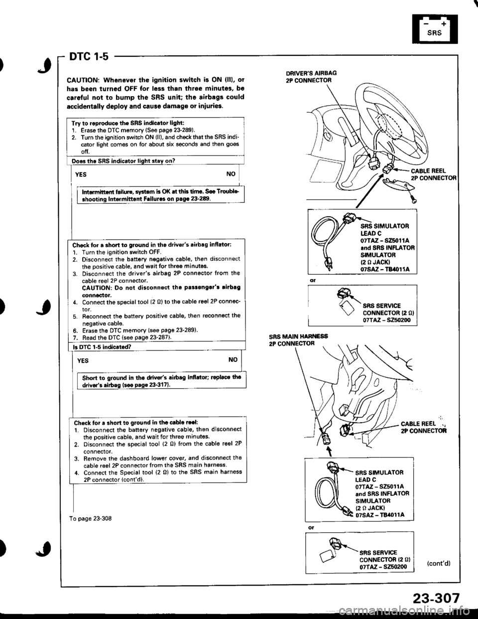
DTC 1-5
CAUTION: Whenever thc ignition switch i3 ON (lll, ot
has been turned OFF for less than throe minutss, bo
caretul not to bump the SRS unit; the airbsgs could
accidcntally deploy and cause damage or iniuri6.
DRIVER'S AIRBAG2P CONNECTOR
\"o""'"o'
CABI.E REEL
{cont'd}
)SRS SERVICECoNNECTOR 12 0)07TA2 - S250200
';
CABLEREEL.,2P OONNECTOF
)
ol
SRS SERVICECoNNECTOR (2 0l
07TAZ - SZSo2(xt
Try to ..produco the SRS indicator light:1. Erase the DTC memory (See page 23-289).2. Torn the ignition switch ON (ll), and chockrhattho SRS indi-cator light comes on for about six seconds and then goes
off.
Ooes ihe SRS indicator lighl slay on?
rffit
i .hooting ldt.rnittont Frilul.. on p.g. 23-289. I
Chock to. a 3hort to glound in tho drivor's airbag inflato.:
1. Turn the ignition switch OFF.2. Disconnect the battery nggative cable, then disconnect
the oositive cable, and wait forth.oe minutes.
3. Disconnect the driver's airbag 2P connoctor from the
cable reel 2P connector.CAUTION: Do not disconnsct tha pt!3onga]'t rirbrg
connoctor.4. Connect the special tool (2 0) to tho cable reel 2P connec_
tor,5. Reconnect tho battery positive cablo, then reconnoct the
negativ€ cable.6. Erase the DTC memory (see page 23-289)
7. Read the DTC (see pag623-2871.
k DTC 1-5 indicated?
YESNO
Sho.t to gtound in tha drive/s ri6ag infi.tor; ruplaco tho
drivor'3 .irbss (s.o p.g€ 23-3171.
Ch.ck tor a 3ho.t to gtound in tha cable ?ral:
1. Disconnect the battery negative cable. then disconnect
the oositive cable, and wait for three minutes.
2. oisconnect the special tool (2 0) lrom the cable reel 2P
connector,3. Remove the dashboard low€r cove., and disconnecl thg
cable reel 2P connector lrom the SRS main harn6ss,1. Connect the Special tool (2 0) to the SRS main harness
2P connoctor lcont'd).
To page 23-308
07TAZ - SZ50t1A.nd SRS INFLATORSIMULATOR{2 0 JACK}07SAZ - TB/OI lA
SRS SIMULATORLEAD C07TAZ - SZ501rAand SRS INFLATORSIMULATOR(2 0 JACKI07SM - TBi|t}l1A
23-307