fuse HONDA INTEGRA 1998 4.G Workshop Manual
[x] Cancel search | Manufacturer: HONDA, Model Year: 1998, Model line: INTEGRA, Model: HONDA INTEGRA 1998 4.GPages: 1681, PDF Size: 54.22 MB
Page 1350 of 1681
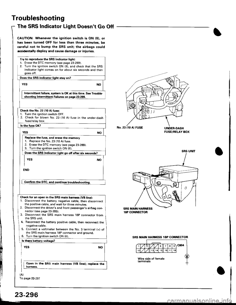
Troubleshooting
The SRS Indicator Light Doesnt Go Off
CAUTIOi{: Whenever the ignition switch is ON (ll). or
h.s bGGn turned OFF for less than three minutes. be
crrclul noi to bump the SRS unit; the airbags could
lcci{tcntrlly deploy and cause damage or iniuries.
(A)
1o page 23-297
Try to reproduce the SRS indic.tor l;ght;l. Erase the DTC memory (see page 23-289).2. Turn the ignition switch ON (ll), and check that the SRSandicator light comes on lor about six seconds and thenooes off,
Ooes the SRS indicetor light stay on?
NOYES
Intermittc t failu.e, sydem is OK dt this time. Sec Troublo-shooting lntermitteirt Failuros on p.qe 23-28!1.
Check tho No. 23 {10 A) fuse:1. Turn the ignition switch OFF-2. Check for blown No. 23 110 A) fuse in the unde.dashfuse/relay box.
ls the luse OK?
YESNO
Roplsce the f!se, and eresc the memory1. Replace the No. 23 (10 Alfuse.2. Erase the DTC memory (see page 23-289).3. Turn the ignition switch ON (ll).
Does th6 SRS indicator light go off after rix socond6?
I YEs No
I
ENO
Contilm the DTC, and continuo troubleshooting.
Check tor an open in ths SRS main hlrna3r (VB tinc):1- Disconnect the battery negative cable. thon disconnectthe positive cable, and wait tor three mrnures.2. Disconnect the driver's and front passenger's airbag con-nector (see page 23 285).3. Disconnect the SRS main harness 18P connector fromthe SRS unit.a. Reconnect the battery positive cable, then reconnect thenegative cable.5. Connect a voltmeter between the No. 3 terminal (+) otthe SRS main harness 18P connector and ground.6. Turn the ignition switch ON {ll).
ls th.re bettery vohaqe?
YES
Open in th. SRS msin h.rness (VB linc); roptrca tha
NO
No.23110 Al FUSEUNOER.DASHFUSE/RELAY AOX
SRS UNIT
SRS MAIN HARI{ESS 18P COI{I{ECTOR
Page 1351 of 1681
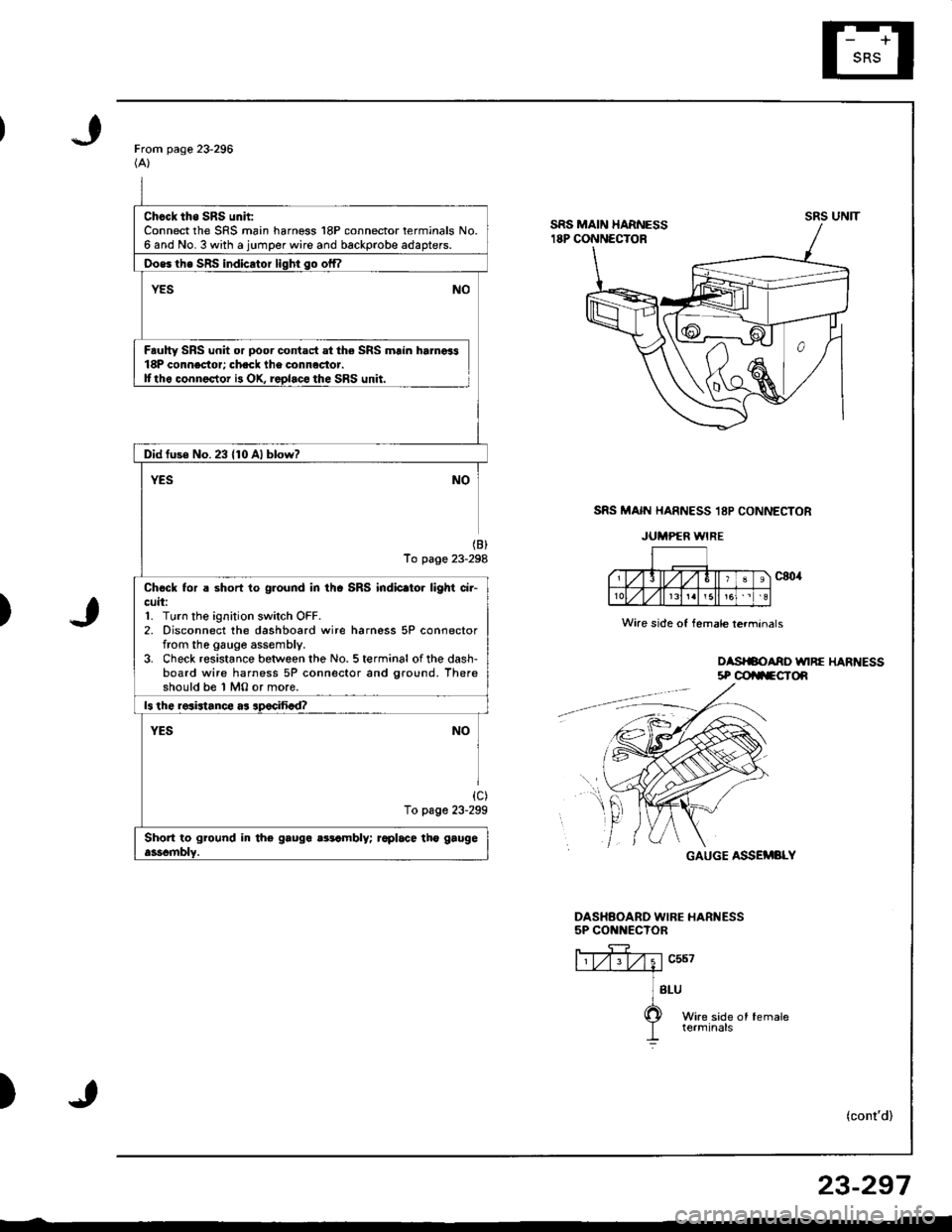
Chcck tho SRS unh:Connect the SRS main harness 18P connector terminals No.6 and No. 3 with a jumper wire and backprobe adapters.
Oos6 th6 SRS indicator liqhi so offl
YESNO
Faulty SRS unit or poor contact at the SRS main hamoi318P connector; check lhe connactor.Ittho connector i3 OX, replaco the SRS unit.
Did fuse No.23 {10 Al blow?
YESNO
(B)
To page 23-298
Chock tor a short to ground in thc SRS indic.tor light ci.-cuit:1. Turn the ignition switch OFF.2. Disconnect the dashboard wire harness 5P connectorfrom the gauge assembly.3. Check resistance between the No. 5 terminal of the dash-board wire harness 5P connector and ground. Thereshould be 1 MO or more.
ls the resistance as apocifiad?
YESNO
{c)To page 23-299
Short to ground in tho gauga aatambly; raplace tho gaugeasscmblY.
From page 23-296(A)
SRS MAIN HARNESS 18P CONNECTOR
JUMPER WIRE
)
oasrSoAno unRE HARt{Ess5P @ilFCTOn
GAUGE ASSEMBLY
DASHAOARD WIBE HARNESS5P CONNECTOR
ffiv;1"u*---.--a
] sru
O wire side of female
I terminals
)(cont'd)
UNITsRs
Wire side of female lerminals
f,t
r
23-297
Page 1375 of 1681
)6.
7.
8.
Connect a 12 volt battery to the tool:
. lf the green light on the tool comes on, the alr-
bag igniter circuit is defective and cannot deploy
the airbag. Go to Damaged Airbag Specia I
Procedure.
. lfthe red light on the tool comes on, the airbag is
ready to be deployed.
Push the tool's deployment switch The airbag
should deploy (deployment is both highly audible
and visible; a loud noise and rapid inflation of the
bag, followed by slow deflation).
. lf the airbags deploy and the green light on the
tool comes on, continue with this procedure
. lf an airbag doesn't deploy. yet the green light
comes ON, its igniter is defective. Go to Dam-
aged Airbag Special Procedure.
!!@ During deployment, the airbag c8n
become hot enough to burn you Wait thirtY min-
ut€s after d€ployment befote touching the assem-
blv.
Dispose of the complete airbag. No part of it can be
reused. Place it in a sturdy plastic bag, and seal it
securery.
CAUTION:
. wear a lace shield and gloves when handling a
deployed airbag.
. Wash your hands and rinse them well with
water after handling a deployed sirbag
)
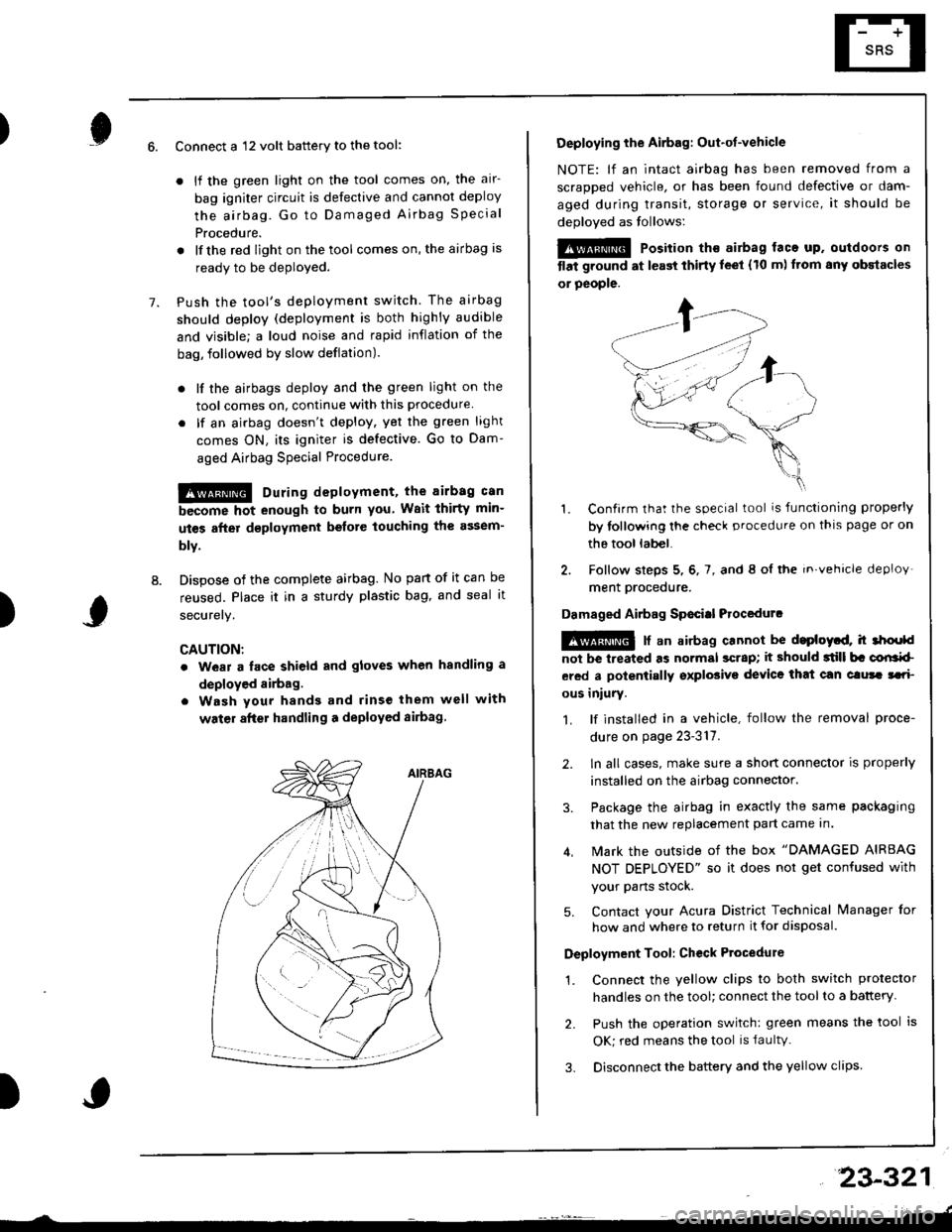
Deploying the Airbag: Out-ot-vehicle
NOTE: lf an intact airbag has been removed from a
scraDDed vehicle, or has been found defective or dam-
aged during transit, storage or service, it should be
deoloved as follows:
@@ Position th€ airbag laca up. outdoors on
tlat ground at l€ast thirty leet (10 m) ftom any obstacles
or people.
1. Confirm that the special tool is functioning properly
by tollowing the check procedure on thls page or on
the tool lab€|.
2. Follow steps 5, 6, 7, and 8 ol the in.vehicle deploy'
ment orocedure.
Damaged Airbag Sp€citl Procedurc
!@ [ an airbag cannot be d.ploytd, h 3hoold
not be lreated as normal scrap; it should 3till b. corlrkl
ered a polentially sxplosive device that can clura tari
ous iniury.
1. lf installed in a vehicle, follow the removal proce-
dure on page 23-317.
2. ln all cases, make sure a short connector is properly
installed on the airbag connector.
3. Package the airbag in exactly the same packaging
that the new replacement part came In.
4. Mark the outside of the box "DAMAGED AIRBAG
NOT DEPLOYED" so it does not get confused with
your Parts stock.
5. Contact your Acura District Technical lvanager for
how and where to return it for disposal.
Deployment Tool: Ch€ck Ptocedure
1. Connect the yellow clips to both switch protector
handles on the tool; connect the tool to a battery
2. Push the operation switch: green means the tool is
OK; red means the tool is faultv.
3. Disconnect the battery and the yellow clips
23-321
Page 1383 of 1681
).1
Contents
How to Use This l\.4anual 1Circuit Schematics (see Circuit Index)Fuse/Relaylnformation 6ComponentLocation Photographs 201
Connector Cavity Numbers 202Connectorldentification 203
Ground-to-Components Index 6-6Wire Harness Routing 203Circuit ldentification lor ln-Line and Fuse Box Connectors
Circuit Index
Air conditionerAir delivery 61Blower controls 60Compressor controls 62Fans 63Anti-lock brake system (ABS) 44A/T gear position indicator 89Automatic transmission controls'98199 models 39'00 models 39-4Back-up lightsHatchback 110Sedan 110- 1Brake system indicator light
USA 71Canada 71-1Brake lightsHatchback 110-6Sedan 110-7Cargo area light (Hatchback) 114-3Ceiling light 114-2Charging system 22Cigarette lighter 155
Clock 154Condenser fan 63Console lights 114Cruise control 34Dash lights 1 14Daytime running lights 110-8Door open indicator 114-2Engine coolant temperature gauge 81Engine oil pressure indicator light 72Fog lights 110-14Front parking lights 110-11Front side marker lights 110-11Fuel gauge 81Fuse/relay boxUnder-dash 6Under-hood 6-3Under-hood ABS 6-5Gauges 81Glove box light 114Ground distribution 14Ground-to-Componentsindex 6-6Hatch open indicator '114-3
Hatch opener '134
Hazard warning lightsHatchback 'l l0-2Sedan 110-4Headlights 1'10-8Headlight switch 100HeaterAir delivery 61Blower controls 60Fanswith A,/C 63without A,/C 63-2Horns 40lgnilion key reminder 73lgnition system 20
204
lmmobilizer system ('00 model) 132lndicators 80Integrated control unit 70Interlock system'98199 models 138'00 models 138-1License plate lightsHatchback 110-12Sedan 110-13Lights-on reminder 73Low fuel indicator light 74l\,4aintenance reminder light 83l\iloonroof 122Odometer 81-1Power antenna 151Power distributionBattery to ignilion switch, fuses, and relays
Fuses to relays and components 10-2Power door locksHatchback '130
Sedan 130-2Power mirrorsHatchback 141Sedan 141-1Power windowsHatchback 120Sedan 120-2Programmed fuel injection system (PGM-Fl)'98199 models 23'00 models 24Radiator fanwith tuC 63without A,/C 63-2Rear parking lightsHatchback 110-12Sedan 110- 13Rear window defogger 64Seat belt reminder 73Security system 133Speedometer Il-1Spotlights 114-2Starting syslemAutomalictransmission 21l\.4anualtransmission 21-1Stereo sound system 150Supplemental restraint system (SRS) 47Tachometer 81- 1TaillightsHatchback 110-12Sedan 110-13Trailer lighting conneclor 118Trunk lid open indicator 114-3Trunk light (Sedan) 114-3Turn signal lightsHatchback 110-2Sedan 110-4Vehicle speed sensor (VSS) 33Wiper/washerFront 91Rear 92
10
).1
I
Xr
12Fg oAmerican Honda Motor Co., Inc. - All Rights Reserved Service Communications 275 pages
Page 1385 of 1681
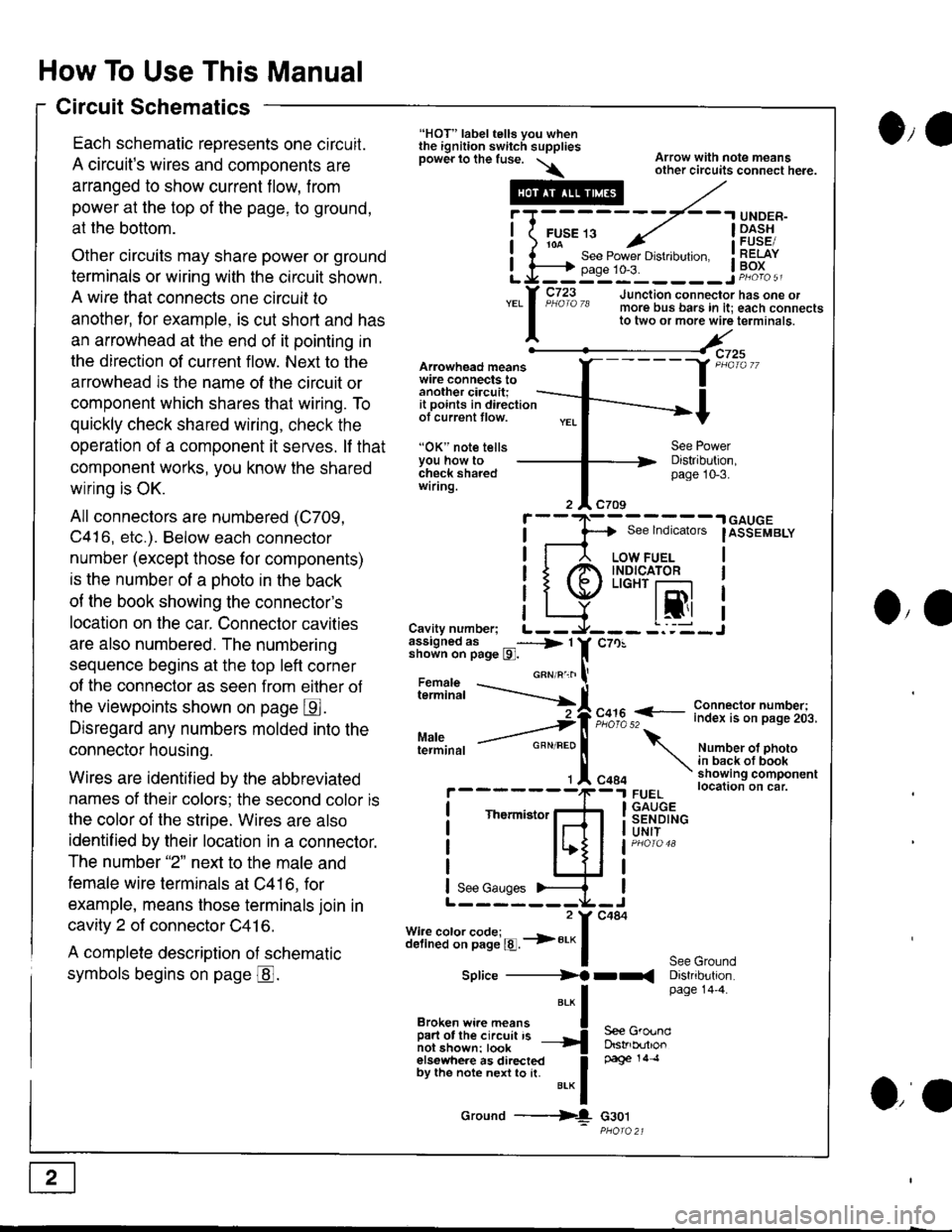
How To Use This Manual
Circuit Schematics
Each schematic reoresents one circuit.
A circuit's wires and components are
arranged to show current flow, from
power at the top of the page, to ground,
at the bottom.
Other circuits may share power or ground
terminals or wiring with the circuit shown.
A wire that connects one circuit to
another, lor example, is cut short and has
an arrowhead at the end of it pointing in
the direction of current flow. Next to the
arrowhead is the name ol the circuit or
component which shares that wiring. To
quickly check shared wiring, check the
operation of a component it serves. lf that
component works, you know the shared
wiring is OK.
All connectors are numbered (C709,
C416, etc.). Below each connector
number (except those for components)
is the number of a ohoto in the back
of the book showing the connector's
location on the car. Connector cavities
are also numbered. The numbering
sequence begins at the top left corner
of the connector as seen from eilher of
the viewpoints shown on page E.
Disregard any numbers molded into the
connector housing.
Wires are identif ied by the abbreviated
names of their colors; the second color is
the color of the stripe. Wires are also
identif ied by their location in a connector.
The number "2" next to the male and
female wire terminals at C416, for
example, means those terminals join in
cavity 2 of connector C41 6.
A complete description of schematic
symbols begins on page @.
O,e
Arowhead meanswire connects toanother ciacuit;it points in directionof current tlow.
"OK" note tellsYou how tocheck sharedwiring.
"HOT" label tells you whenthe ignition switch suppliesDower lo the fuse. \\
.---#
"*l
Broken wi.e means I
ffir"i:'ffi:[:l''" -{
elsewhere as directed Ioy ttt" not" n"n to [. u.* f
Ground ---{
Arrow with note meansother circuits connect here.
Distribution,page 10-3.
See lndicators
I
.| GAUGE
IASSEMBLY
I
I
I
IJO,'
i"?*i,h -..--.-{[
Cavity number; L--assigned as _----> 1shown on page l9l.
Maleterminal
c70!
F,":,2 f
- i":!f $l ?:T"'i,.i,.
Number ot photoin back ot bookshowing componentlocation on car.FUELGAUGESENDINGUNIT
See GroundDistribution.page 14'4.
c484
Thermistor
See Gauges
Splice ----------)f rr(
S€e GroundDstrb(rtlonpage 14 .l
G30t
iT;
Li=
- -.I UNDER-
FUsE 13 ../ I -Dl^s!io-a-- - , iFUsESee Power Drstlbulton. I RELAYpase 1o-3. ! Po^{^ -__:_____ ___Jp"otoa
o,a
Page 1386 of 1681
)o
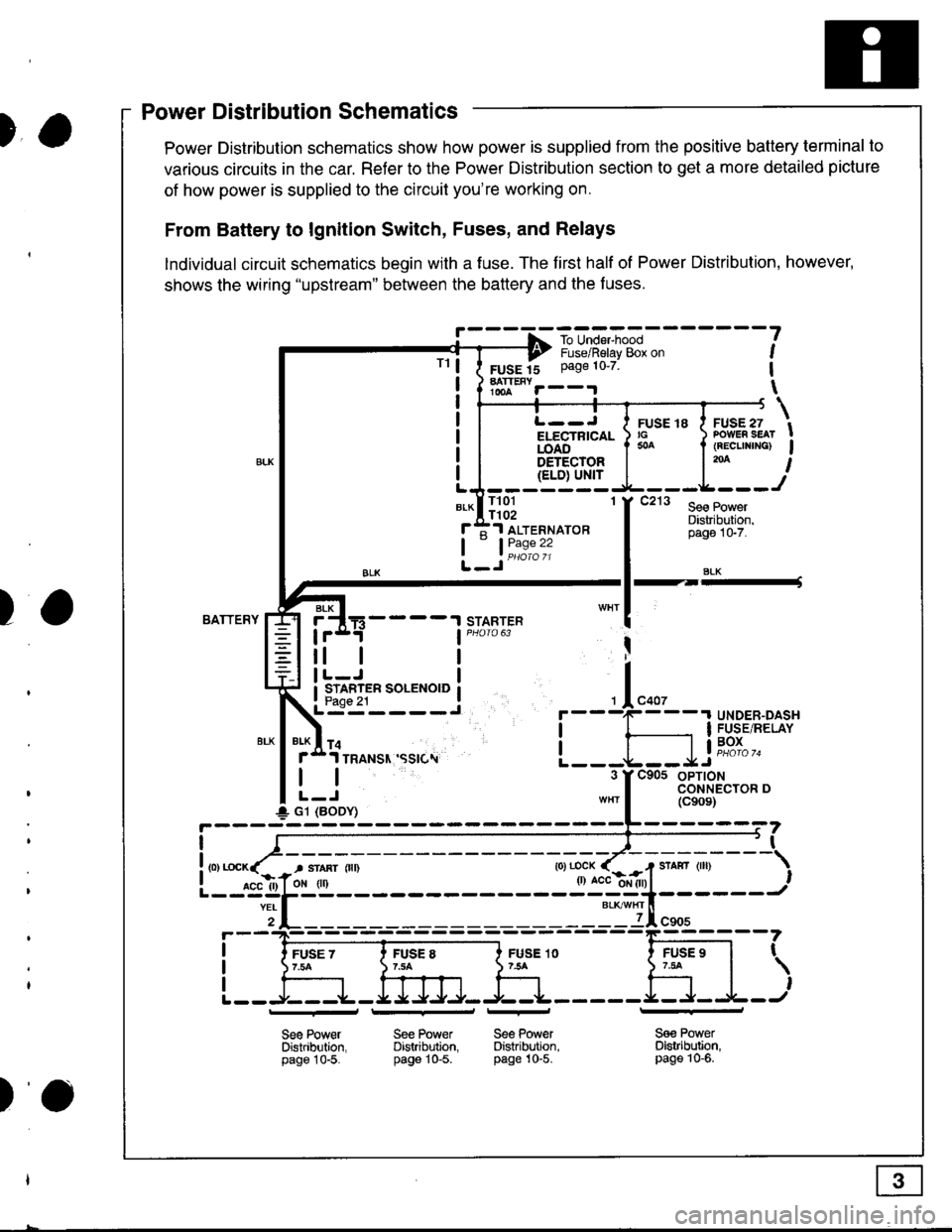
)a
)wer IJrstnDullon Scnemallcs -
Power Distribution schematics show how power is supplied from the positive battery terminal to
various circuits in the car. Refer to the Power Distribution section to get a more detailed picture
of how power is supplied to the circuit you're working on.
From Battery to lgnition Switch, Fuses, and Relays
lndividual circuit schematics begin with a fuse. The first half of Power Distribution, however,
shows the wiring "upstream" between the battery and the f uses.
!' - - - -f -ro-unE,-"*l - - - - - - -
?---? i,"-")il"i"v-g& o" ,
FUSE 15 Page 10'7 1
hTt""r--.r \
TrL--J I ruse re I ruse zi/ ru:rE ro a .v-E., tELECTRTCAL ) rc ) PowER sEAr !iOA6".'-'- I * I (REcuNrNG) Igs-r-qqrg! | l'* I{ELD) Ul'{rLJ-------
*-lll3l 'f t"' l*.r:::f ;1 ALTERNAToR
tL_Jii1:"":
Distribuiion,pago 1G7.
SLK
BATTERYSTARTERBLK
4----t
tl
STARTER SOLENOID
I
I
+ G1 (BODY)
r
I
I
I
FUSE 1O754
Sge PowerDistribltion,page 10-5.
FUSE 97.tat
,
l---r+J
See Power Se€ PowerDistribution. Distribution.page 10-5. pag€ 10-5.
_l_
Sa€ PowerDistribution,page 10-6.
Power Distribution Schematics
tt
)o
Page 1387 of 1681
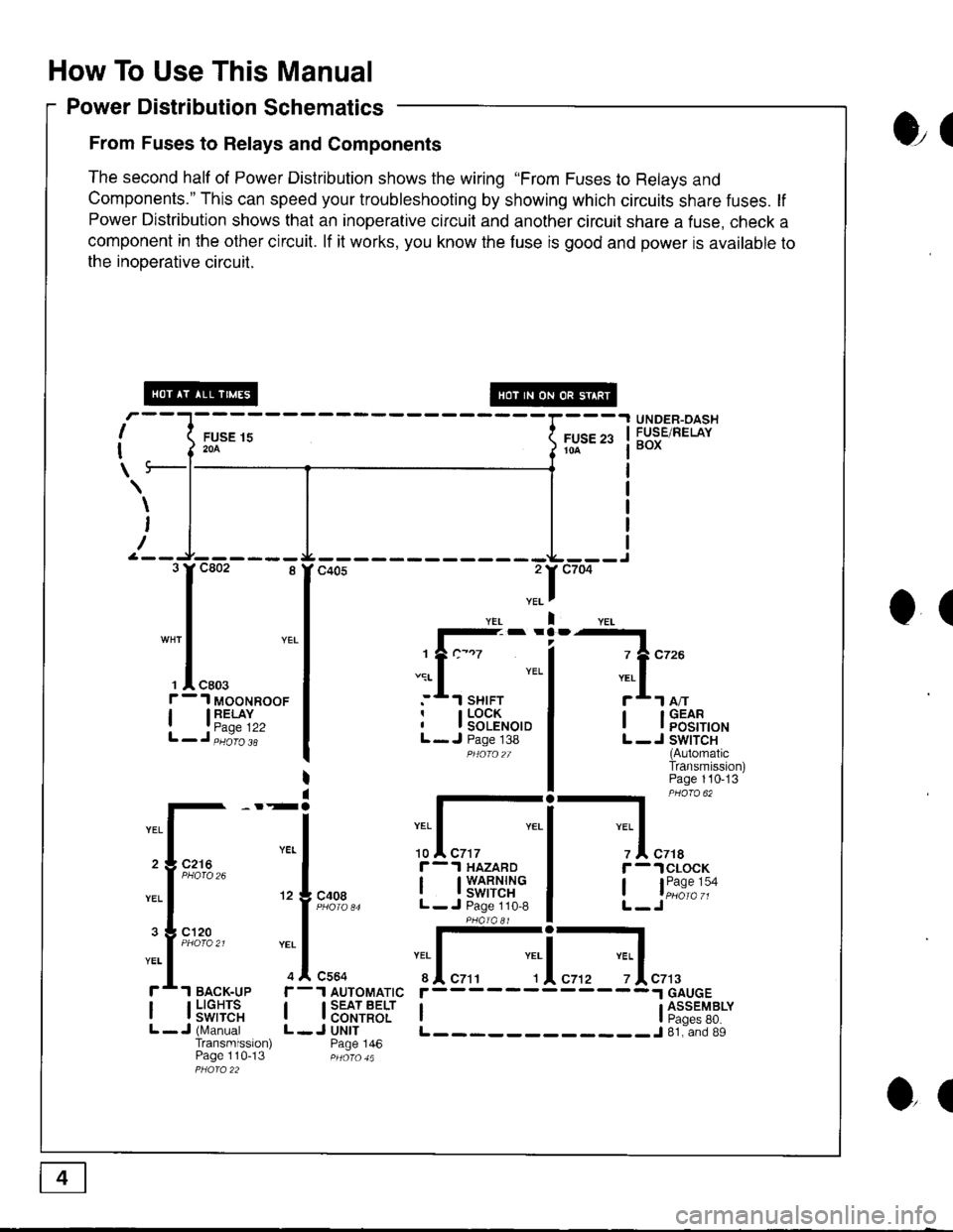
How To Use This Manual
Power Distribution Schematics
From Fuses to Relays and Components
The second half of Power Distribution shows the wiring "From Fuses to Relays and
Components." This can speed your troubleshooting by showing which circuits share fuses. lf
Power Distribution shows that an inoperative circuit and another circuit share a fuse, check a
component in the other circuit. lf it works, you know the fuse is good and power is available to
the inooerative circuil.
ol
I
I
\
FUSE 15204
UNDER-OASHFUSE/RELAYBOXFUSE 2310A
\
I
/
O(
.II
l-- -
1?c-.7
.:r- I YEL
:*.l sHrFTr I LOCKI I SOLENOIDL- J Page 138PHOfO2T
I lFEt[,o'
L -J SWITCH(AutomaticTransmission)Page 110-13
-l PHaro 62
IYEL Iz I czrar -.lclocK
, l"i1:"':oL-Jc408
r-.l HAZARD
I t3'�S[t''i"L- J Page 110,8
:I-c564
1 AUTOMATIC
I SEAT BELTI CONTROLJ UNITPage 146
YEI
r
IL
c7t3
I l5"f,TE'"L -J (N,4anualTransmission)Page 110-13
r------
I ti:*'"T8*L____________J 81. and 89
3rc802 8
I
"* | YEL
I
', I "ro.f - 1 MooNRooF
| 13"'^TI",L-J,iiio'i'
2 3 C216
3 g cl20
ol
Page 1390 of 1681
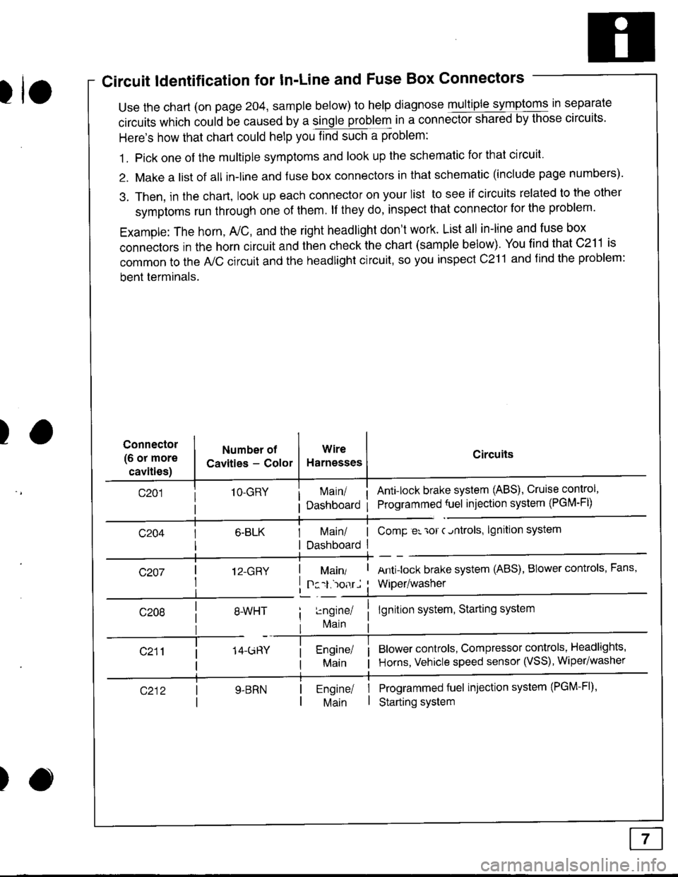
Circuit ldentification for In'Line and Fuse Box Connectors
tuse the chart (on page 204, sample below) to help diagnose multiple symptoms in separate
circuits which could be caused by a single problem in a connect,oishared by those circuits'
Here's how that chart could help you find such a problem:
1. Pick one of the multiple symptoms and look up the schematic for that circuit'
2. Make a list of all in-lrne and fuse box connectors in that schematic (include page numbers).
3. Then, in the chart, look up each connector on your list to see if circuits related to the other
symptoms run through one of them. lf they do, inspect that connector for the problem.
Example: The horn, A,/C, and the right headlight don't work. List all in-line and fuse box
connectors in the horn circuit and then check the chart (sample below). You find that C211 is
common to the A,/C circuit and the headlight circuit, so you inspect c211 and find the problem:
bent terminals.
)Connector
(6 or more
cavities)
Numbel of
Cavities - Color
1O-GRY
I 12-GRY
I
Wire
Harnesses
I Main/ | ComP er 'ror c.ntrols,
I Dashboard I
Circuits
Ant!lock brake system (ABS), Cruise control,
Programmed {uel injection system (PGM-FD
!ngrnei
lvlain
lgnition system
Antilock brake system (ABS), BIower controls, Fans,
Wiper/washer
lgnition system, Starting system
Blower controls, Compressor controls, Headlights'
Horns, Vehicle speed sensor (VSS), Wiper/washer
Programmed fuel injection system (PGM-Fl)'
Starting system
Engine/ |Main I
)
Page 1391 of 1681
How To Use This Manual
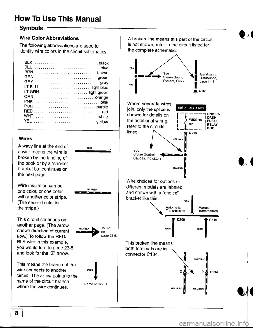
Symbols
Q,(Wire Color Abbreviations
The following abbreviations are used to
identify wire colors in the circuit schematics:
BLK.... .........btack
BLU.... ......... btueBRN .... ........ brown
GRN.... ........ green
GRY .... ......... gray
LTBLU . ..... tighrbtue
LTGRN. ....ljghtgreen
ORN.... ....... orangePNK.... ..........pink
PUR .... ........ purpte
RED .... .......... redwHT... .,.......white
YEL .... ........ ye ow
A broken line means this part ot the circuit
is not shown; reler to the circuit listed for
the complete schematic.
",.I
ar
*.1
See GroundDistribution,page 14-1.
1G101
Where separate wires
join, only the splice is
shown; for details on
the additional wiring,
refer to the circuits
listed.i-l{:i
;["
UNDER.DASHFUSE/RELAYBOX
Wires
A wavy line at the end of
a wrre means the wire is
broken by the binding of
the book or by a "choice"
bracket but continues on
the next page.
Wire insulation can be
one color, or one color
with another color stripe.
(The second color is
the stripe.)
This circuit continues on
another page. (The arrow
shows direction of current
flow.) To follow the RED/
BLK wire in this example,
you would turn to page 23-5
and look for the "2" aftow.
This means the branch of the
wire connects to another
circuit. The arrow points to the
name of the circuit branch
where the wire continues.
BLK-Crulse Controt, QaalGauges, Indrcarors
!YEUBTK
II
Wire choices for options or
different models are labeled
and shown with a "choice"
This broken line means
both terminals are in
connector C134.
bracketlikethis
*J
Q,(
ManualTransmission
*'ffil:,*"1"' *"1""0
I
"""1
H
Name of Circuit
cl34
a,ll
Page 1393 of 1681
How To Use This Manual
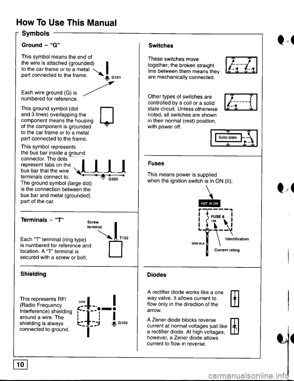
Symbols
Ground - "G"
This symbol means the end of
the wire is attached (grounded) Ito the car frame or to a metal Ipart connected to the f rame. \I orol
,
Each wire ground (G) ," -/numbered for reference.
Q,(Switches
These switches move
together; the broken straight
line between them means thev
are mechanically connected.
Other types of switches are
controlled by a coil or a solid
state circuit. Unless otherwise
noted, all switches are shown
in their normal (rest) position,
with power off .
This ground symbol (dot
and 3 lines) overlapping the
component means the housing
of the component is grounded
to the car f rame or to a metal
part connected to the f rame.
This symbol represents
the bus bar inside a ground
connector. The dots a
i"r*"""*nn"l,':" .,.L I I I
lermtnals connectto. -'--'-:t"'--------<
The ground symbol (large dot)
: Gsoo
is the connection between the
bus bar and metal (grounded)
part of the car.
Terminals - "T"
m
ffi
Solid-state
Fuses
This means power is supplied
when the ignition switch is in ON (ll).
Diodes
A rectifier diode works like a one
way valve. lt allows current to
flow only in the dlrection of the
arrow.
A Zener diode blocks reverse
currenl at normal voltages just like
a rectifier diode. At high voltages,
however, a Zener diode allows
current to flow in reverse.
Q,(
Each 'T" terminal (ring type)
is numbered for reference ano
location. A "T" terminal is
secured with a screw or bolt.
Shielding
This represents RFI
(Radio Frequency
Interf erence) shielding
around a wire. The
shielding is always
connected to ground.
,,,
n
:'iL.-!
L-_+i !",*
I