HONDA INTEGRA 1998 4.G Workshop Manual
Manufacturer: HONDA, Model Year: 1998, Model line: INTEGRA, Model: HONDA INTEGRA 1998 4.GPages: 1681, PDF Size: 54.22 MB
Page 1491 of 1681
- How the Circuit Works
The low engine oil pressure indicator light works in
two ways: il flashes continuously following a
momentary loss of engine oil pressure, or it comes
on and stays on with a complete loss of engine oil
oressure,
When the engine first starts, before its oil pressure
rises above 4.3 psi, voltage is applied to the closed
and grounded engine oil pressure switch and the
light comes on to test the bulb.
With the engine running, voltage is applied at the
WHT/BLU wire of the integrated control unit. With
normal engine oil pressure, the engine oil pressure
switch is open and the low oil pressure indicator
light does not come on. lf the engine oil pressure
switch closes momentarily (more than 0.5 seconds)
but then opens again, the YEURED wire at the
integrated control unit will sense ground through the
switch. The integrated control unit will then provide
and remove ground for the low oil pressure indicator
light through the YEURED wire. The light will flash
on and off until you turn the ignition switch off. The
flashing feature will not work until 30 seconds after
initial voltage is applied to the WHT/BLU wire of the
oil pressure indrcator llasher circuit. This delay
keeps the low oil pressure indicator light from
coming on during engine warm-up.
lf engine oil pressure falls below 4.3 psi and does
not increase, the engine oil pressure switch will stay
closed. The low oil pressure indicator light will then
come on and stay on.
Refer to the Service Manual (Section 23, Electrical)
for specific tests or troubleshooting procedures.
72-1
Page 1492 of 1681
Seat Belt, Lights-on, and lgnition Key Reminders
wHrFEonP,rolo2j
i lll i .._l:["c'xs;"
@,[rsrB", ! | Rtr-r^9,:: I """"1-""
'-----'F--=-'--;fi;'"i
I ffi;'''ffi'' i :seePower
seeHeadriohtf*;ffJiil?l' r i I'l"J:i'J:"t switch. - | BEEPER | | llpage 100-1. | \-7l | | ver-eru I GAUGE
------{ "r'o l-1 . J "r'o i . .I, cuut oss"t"$ElY
! TNTFI:E^TFn I f=tR--
ii
'*:::i"T''*--t
I I ! i
'?tr*aa----'
i t------lI---)t--.&---.L------j i o.o"'u I
i ff{$;{'F1{""0
"l-T-T"*
i
.*r*,
r- - - - - - -
iTs%
-
t
- -
t
- -
f
- - -*"-l
J
- - -
r-
- - -
"'.o ".,
=== = - -
!
Y
I
t
I
See GroundDistribution,page 14-5.
III
i-I+-'.1.1ilg.',8.J39" i-ru;;-
UNDER'DA.H
I rNrEBroR I BOX I
1-l,I:_j
*-"''
i li[::" li[]::'*"
BOXPHOfA 58
i-_I'31_i
,,^sl F,';1",,
| ,1,**",
r----=!i=-'l
F-oc422
----tnilll- -l$H$ffir"
i i'PT:"x':x*
*[-fui'**- i ioiffit.
:i:ltif"i i ilr-zt
! | LeJ-:
LiohtsONinput
Beeper output
Door Key Seat beltswitch switch swiichinput input input
73
II
Page 1493 of 1681
Low Fuel Indicator Light
!
--------Jc551
See PowerDistribution,page 10-5.
See Gauges, I ASSEMBLYIndicators
LOW FUELINDICATORLIGHT
lrnl
FUSE 25ffETEF7,5ASee PowerDistribution,page 10-5.
I
c505
UNOER.DASHFUSE/RELAYBOX
D4
L-3
10
3c51 l
Thermlstor
SeeGaugesL-------
FUELTANKUNIT
1
Page 1494 of 1681
- How the Circuit Works
Do not smoke while working on the fuel system.
Keep open flame away from the work area. Drain
fuel only into an approved container.
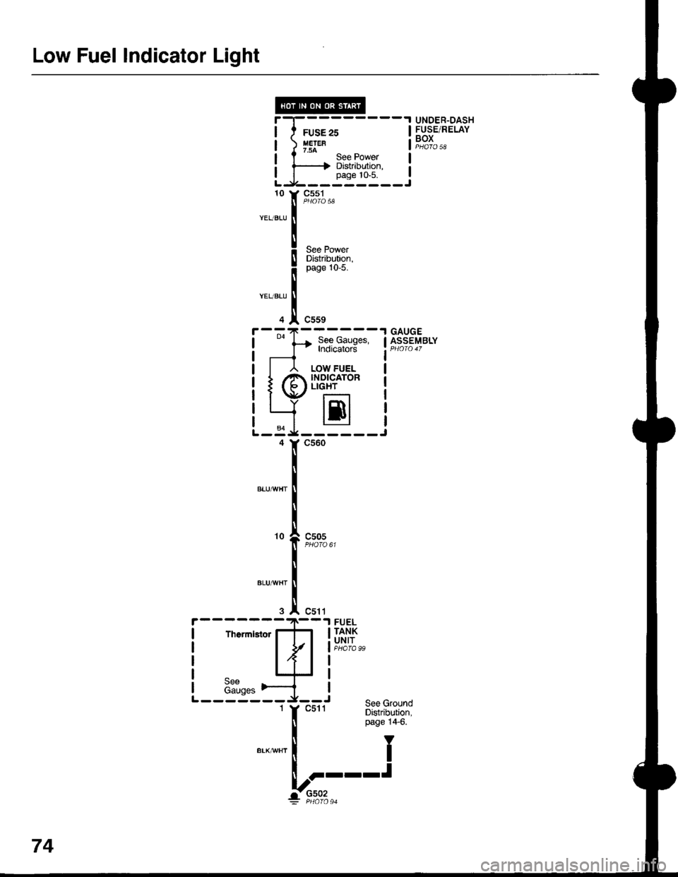
A thermistor is mounted in the fuel tank unit. When
the thermistor is cool, its resistance is very high.
When the thermistor is warm, its resistance
decreases. Fuel in the fuel tank transfers heat away
from the thermislor last enough to keep it cool so
the thermistor's resistance stays high and the low
fuel indicator lighl does not come on. When the fuel
level drops below about 2.2 gallons, the thermistor
is no longer immersed in fuel. Without the fuel to
cool it, the thermistor's resistance decreases,
allowing current to flow through the low fuel
indicator light and the thermistor to ground, and lhe
low fuel indicator light comes on.
Refer to the Service Manual (Section 23, Electrical)
for specific tests or troubleshooting procedures.
74-1
Page 1495 of 1681
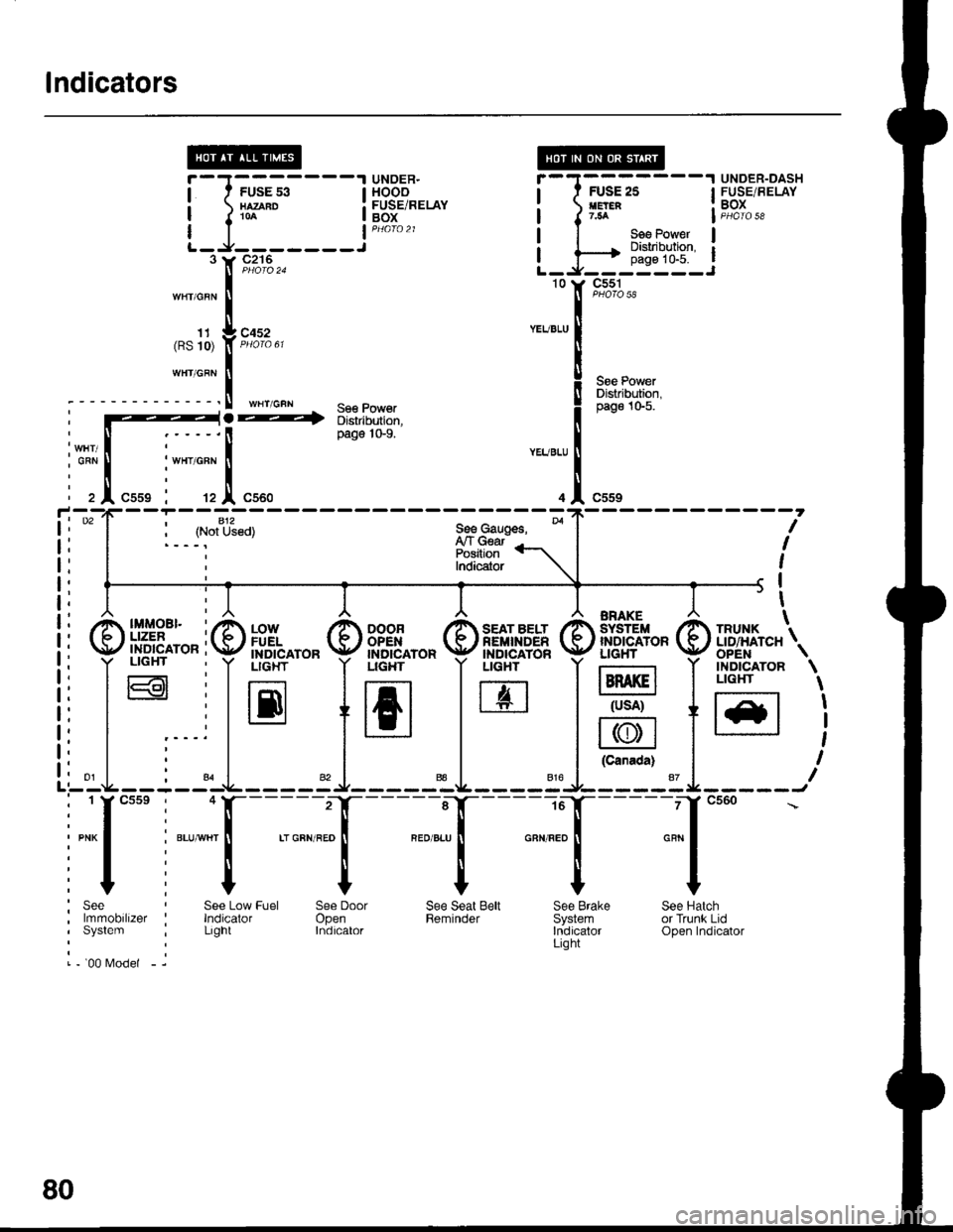
lndicators
UNOER.HOOOFUSE/RELAYBOX
UNDER-DASHFUSE/BELAYBOXJ-rr-.rr1----l
)n*" i
I See Power I
^hiEl'�tli10
J;;,;---
J::____3
c55t
S€e PowerDistribution,pag€ 10-5.
c216
c452
WHT/GFN - se€ Power-> Distribution,
WHT/GBN
11(RS 10)
WHT/GRN
page 'l0-9.
c559
\
\
I
I
,
I
I
i--jltffi*, se€causss' *|
i
ffi"fi?ri\l i
i
) #,8:l;"
i,9, nH^,"",9, mis*"
g
ilH4+fi
g
ffi"",$, FF"1t1;;1\
l:r irr-.-.-r !rn lrz: ltlsft IILr==
ilLSl +16l lLel l* +=-,I l- | ll\y/l l-
i | | | lc"""d") |
- - I - -l-L - - - - : J- - - - -aL - - - - 3'J- - - - - 1 I - - - - - Jcsse, +11------z-lf------e-lf-----ro-][-- -ircs60
i
*, -",
I
., o"n ,.o
|
".0 ".u
I
o"n ".o
[
"*
|
it t t I I, See Low Fuel See Door See Seat Belt See Brake See Hatch,ilizet '. lndicator Open Reminder Svstem or Trunk Lid'1
i Lrght Indrcator tndrcator Open Indicator
rrrer - i
80
Page 1496 of 1681
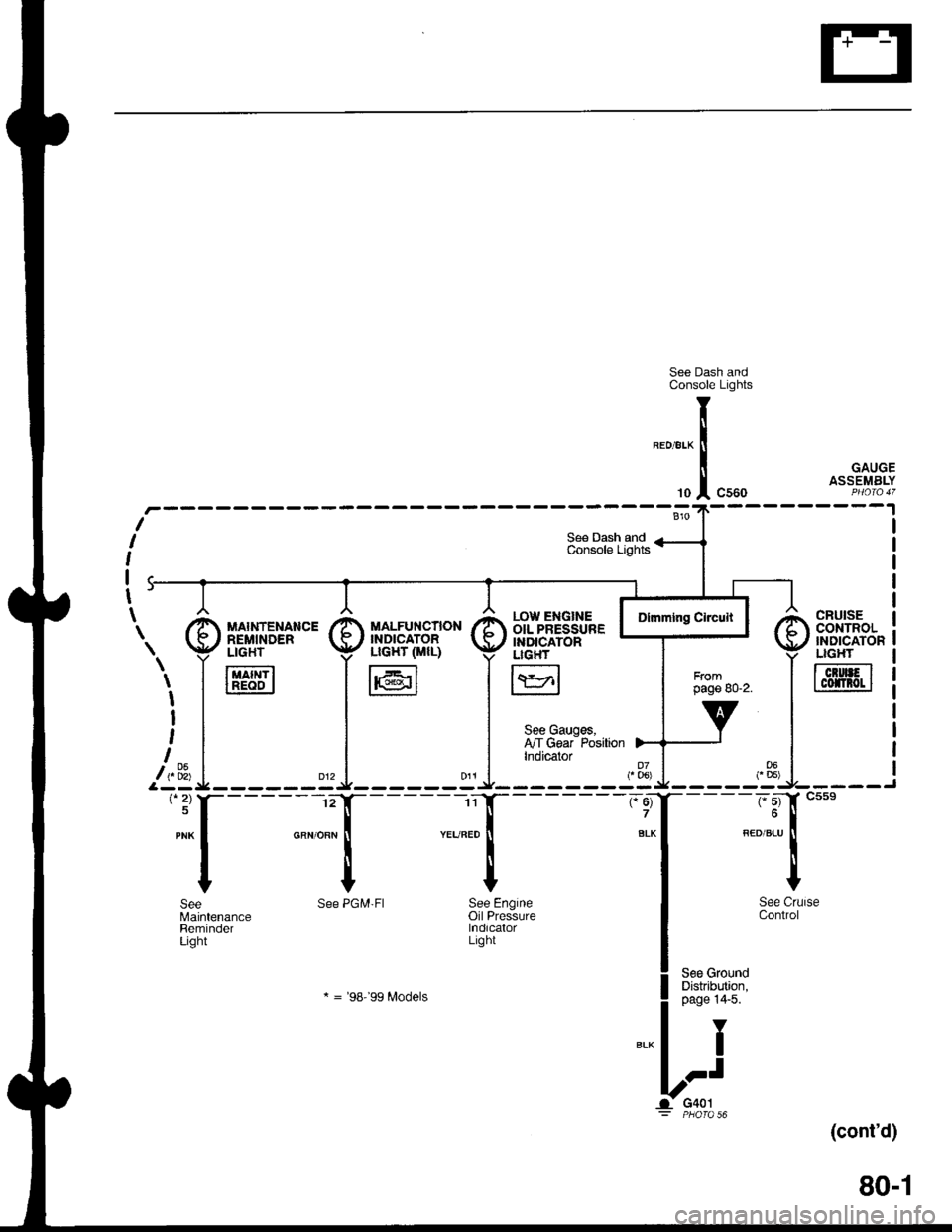
See Dash andConsole Lights
GAUGEASSEMBLY
(cont'd)
80-1
CRUISEcor{TRoL'NDICATONLIGHT
TcrurFlI cofnot I
r.ow ENGTNE IOIL PRESSURE IINDICATORLIGH'
I\YrlL:J
See Gauges,I'lT Gear PositionIndicator
"ff
I
See CrlControl
See GroundDistribution,page 14'5.
Y
I
.-t
G401PHO|O 56
T
li
'"1
See PGM'FI See Engineoil PressurelndicalorLight
* = '98-'�99 Modets
SeeMaintenanceReminderLight
\. I [,'d['*"' I il]i"fl".,B* I
i,1_* =i^ .l
'*f----l- :{
Page 1497 of 1681
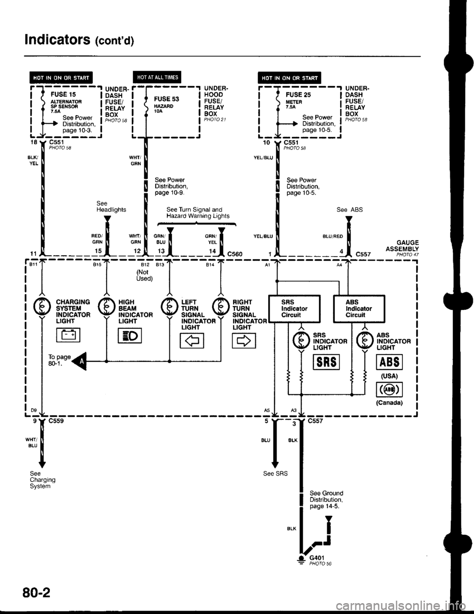
Indicators (cont'd)
@
tt
t(
tt
lt
tl
"-T
!T
!I
gI
IUNDER.HOODFUSE/RELAYBOX
UNDER-DASHFUSE/RELAYBOX
l-J-rr-trr1---l
LJi!*''i
DASHFUSE/RELAYBOX
FUSE s3NAZAAD104
18
BLl(YEL
11
811r
See PowerDistrabution,page 10-9.
See Turn Signal andHazard Warning Lights
SeeHeadlights
V
tlneoi IGRN tI._ I':r__
I
{
I
812
(NorUsod)
___l'd",,,
RIGHTTURNSIGNALINDICATORLIGHT
H
AASINOICATORUGHT
@
(usA)
@(Canada)
"..,::,f
t*'
! ,"" ro*o
il
;:i:it''l
see ABs
"r""." I "., "." trt
, !-------a.1, "uu, ott?fl%tf
sRsINDICATORLIGHT
m
XIGHBEAM'NDICATORLIGHT
E
FUSE 15ALTEANATORsP sEl{son.54
---t Diskibution, :
-rr"t:t--i'C5s1
Page 1498 of 1681
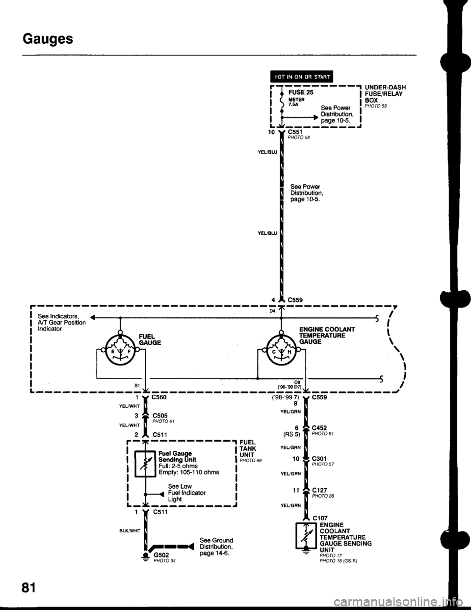
Gauges
I
I
I
I
10
FUSE 25HElEN7.54
FUSE/RELAYBOX
sse Power I eloro sa
Dishibution,:pags 1&5.----.----Jc551
c559
D8(s 99 D7)
(98-'�99 7)8
Seg PowerDistibution,pago l0-5.
ENGIIIE COOI-ANTTEIiPERATUNEGAUGE
I
I
t
\
\
I
,
I---------Jc559
c452PHOTO 61
c127PHOTO 36
c107
c505
c511
YEUGBN
(RS s)
YEL/GBN
10
YEUGRN
Fuel GaugeSendlng UnltFull: 2'5 ohmsEmpty: 10$110 ohms
See LowFuel lndicatorUght
FUELTANKUNITc301
11
YEUCRN
l.'n ENGINEI 1/l COOLANTI .' I TEMPERATUREI 'I I GAUGE SENDING.- UNIT- PHOfA 17PfiOrO r8 (GS B)
81
Page 1499 of 1681
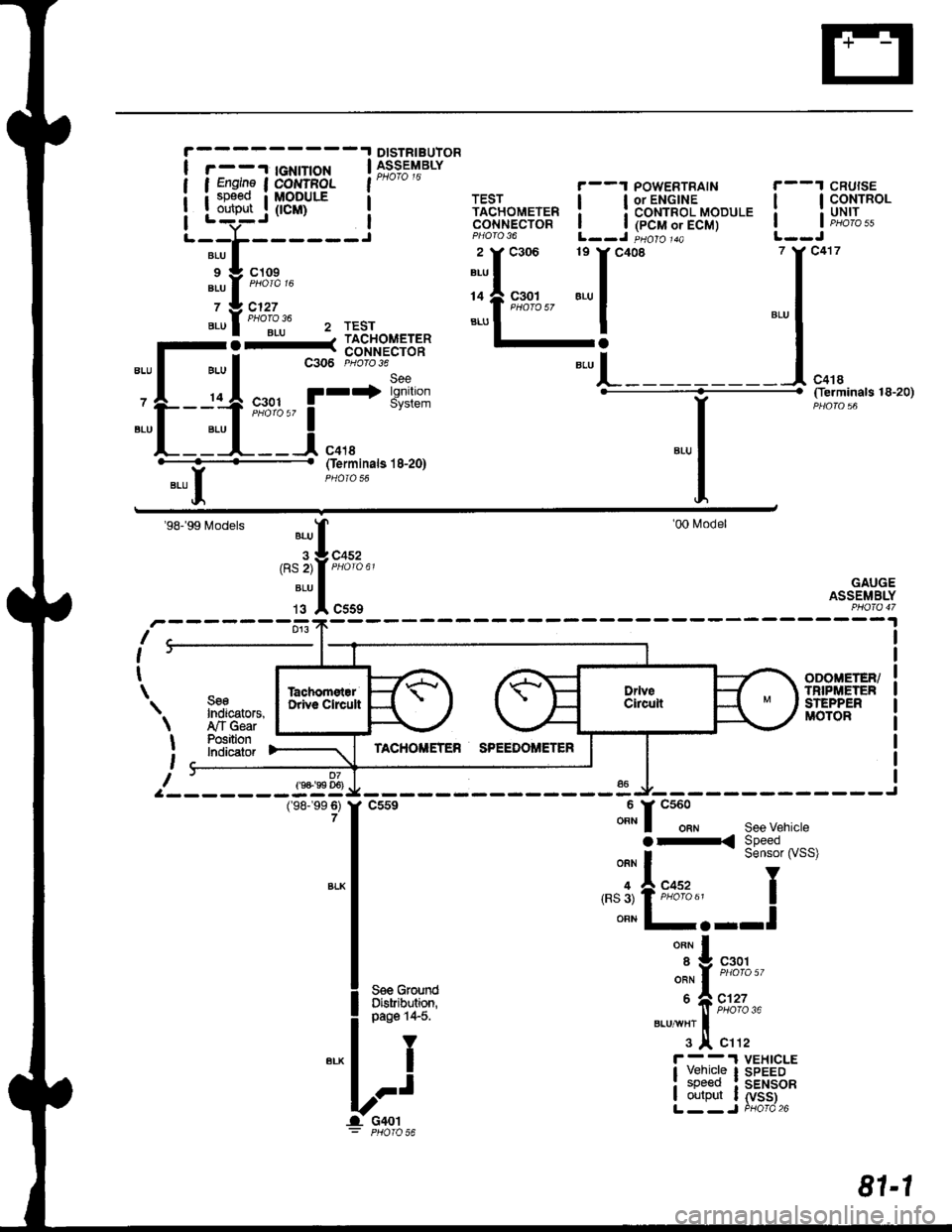
DISTRIBUIOR
r - -'l tGNtT|oN | 39;s;t'rarvI Engine I COI{TFOL l"* " "
i sp€ed i MoDULE a
Louteut .j (tcm) i
'-;t;----i
',i'l:i::'"
".ul""ollju 2 rEsr
-l-_1;.11=1==
-L-:ttt
'r*'i*'*
"-l
(ferminals 18-20)
YBLU II
Oerminals l8-20)
'98-'99 Models
r-------fr:fl;,,
'00l\4odel
GAUGEASSEMBLY
I
I
t
\
9-
SseIndicators,,ry'TGearPositionlndicatof
ODOIIETER/TNIPi,|:TENSTEPPERMOTOR
07f9+'99 D6)
\
I
t
I
(98-'�99 6)7
v------ -"u Jl,-------------J
f
csse ""t" f
"tt"t""
see vehicte
|
":^i:33i#'""'
I '.'3'tFffi"' I
I ""n l-.--l
|
*^l
| .^^^.^..-. ",',f n%',
l** ii*i
Lri ibr,li;tfi
81-1
Page 1500 of 1681
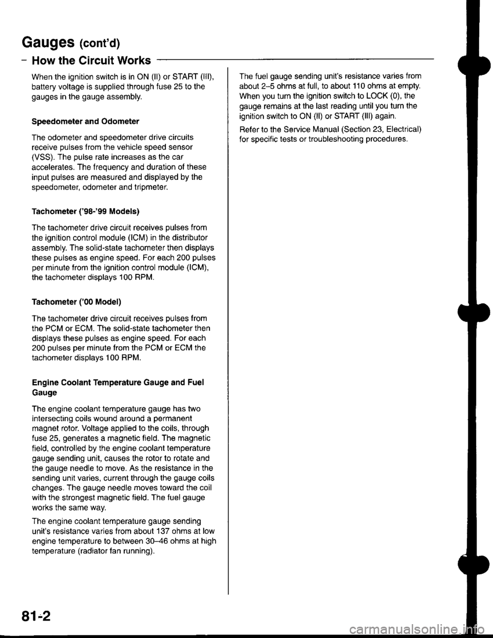
Gauges (cont'd)
- How the Circuit Works
When the ignition switch is in ON (ll) or START (lll),
battery voltage is supplied through fuse 25 to the
gauges in the gauge assembly.
Speedometer and Odometer
The odometer and speedometer drive circuits
receive pulses lrom the vehicle speed sensor
(VSS). The pulse rate increases as the car
accelerates. The frequency and duration of these
input pulses are measured and displayed by the
speedometer, odometer and tripmeter.
Tachometer ('98-'99 Models)
The tachometer drive circuit receives oulses from
the ignition control module (lCM) in the distributor
assembly. The solid-state tachometer then displays
these pulses as engine speed. For each 200 pulses
per minute from the ignition control module (lCM),
the tachometer displays 100 RPM.
Tachometer ('00 Model)
The tachometer drive circuit receives pulses f rom
the PCM or ECM. The solid-state tachometer then
displays these pulses as engine speed. For each
200 oulses oer minute trom the PCM or ECM the
tachometer displays 1 00 RPM.
Engine Coolant Temperature Gauge and Fuel
Gauge
The engine coolant temperature gauge has two
intersecting coils wound around a permanent
magnet rotor. Voltage applied to the coils, through
fuse 25, generates a magnetic field. The magnetic
field, controlled by the engine coolant temperature
gauge sending unit, causes the rotor to rotate and
the gauge needle to move. As the resistance in the
sending unit varies, current through the gauge coils
changes. The gauge needle moves toward the coil
with the strongest magnetic tield. The fuel gauge
works the same way.
The engine coolant temperature gauge sending
unit's resistance varies from about 137 ohms at low
engine temperature to between 30-46 ohms at high
temperature (radiator fan running).
The fuel gauge sending unit's resistance varies from
about 2-5 ohms at full, to about 110 ohms at empty.
When you turn the ignition switch to LOCK (0), the
gauge remains at the last reading until you turn lhe
ignition switch to ON (ll) or START (lll) again.
Refer to the Service Manual (Section 23, Electrical)
for specific tests or troubleshooting procedures.
81'2