Clutch removal HONDA INTEGRA 1998 4.G User Guide
[x] Cancel search | Manufacturer: HONDA, Model Year: 1998, Model line: INTEGRA, Model: HONDA INTEGRA 1998 4.GPages: 1681, PDF Size: 54.22 MB
Page 375 of 1681
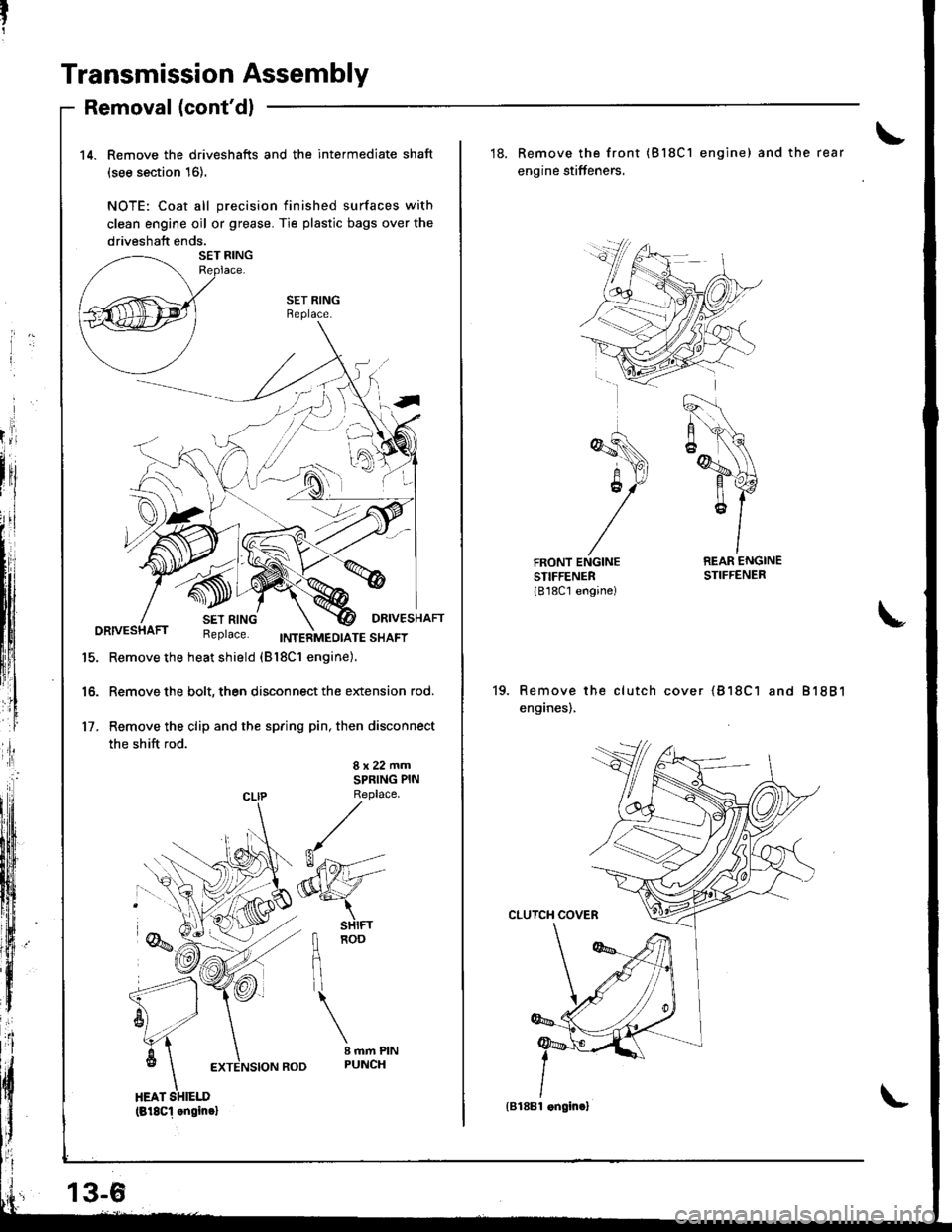
Transmission Assembly
Removal (cont'dl
14. Remove the driveshafts and the intermediate shaft
(see section 16).
NOTE: Coat all precision finished surfaces with
clean engine oil or grease. Tie plastic bags over the
driveshaft ends.
SET RINGBeplace.
DRIVESHAFTDRIVESHAFT Replace. trweinnro,ora ""ot
15. Remove the heat shield (Bl8c1 engine).
16. Remove the bolt, then disconnect the extension rod.
17. Remove the clip and the spring pin, then disconnect
the shift rod.
8x22mmSPRING PIN
CLIP Replace
fl noo
flil
\
I mm PINPUNCH
(818c1 .ngin.l
13-6
'18. Remove the front (Bl8C1 engine) and the rear
engine stiffeners,
REAR ENGINESTIFFENER
Remove the clutch cover {818C1 and 81881
enganes),
{B188l .ngin.}
Page 376 of 1681
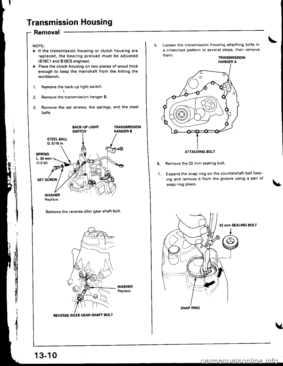
Transmission Housing
Removal
NOTE:
. lf tho transmission housing or clutch housing are
replaced, the bearing preload must be adjusted
(818C1 8nd 818C5 engines).
. Place the clutch housing on two pieces of wood thick
enough to keep the mainshaft from the hifting the
workbench.
1. Remove the back-up light switch.\
2. Remove the transmission hanger B.
3. Remove the set screws, the springs, and the steel
balls.
BACK-UP LIGHTswrTcHTRANSMISSIONHANGER B
STEEL BALLD. 5/16 in
SET SCREW
WASHERReplace.
Remove the reverse idler gear shaft bolt.
13-10
5. Loosen the transmission housing attaching bolts in
a crisscross pattern in several steps, then remove
them.TRANSMISSION
Remove the 32 mm sealing bolt.
Expand the snap ring on the countershaft ball bear-
ing and remove it from the groove using a pair of
snap ring pliers.
6.
7.
ATTACHING BOLT
SNAP RING
32 mm SEALING BoLT
Page 383 of 1681
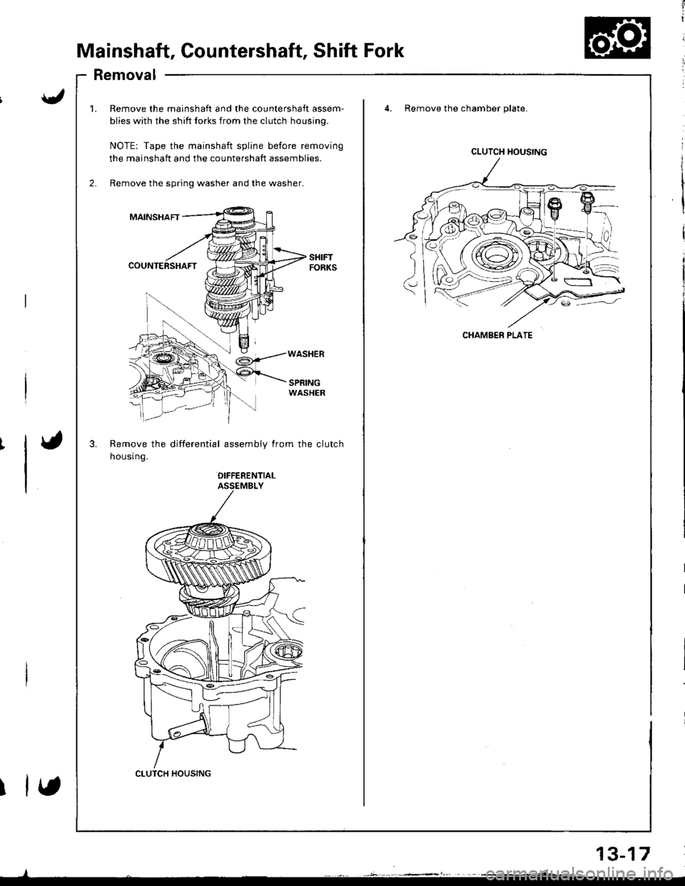
Mainshaft, Countershaft, Shift Fork
Removal
mainshaft and the countershaft assem-
? shift forks from the clutch housing.
the mainshaft spline before removing
ft and the countershaft assemblies.
spring washer and the washer.
differential assembly from the clutch
OIFFERENTIALASSEMBLY
4. Remove the chamber plate.
SPRINGWASHER
1.Remove the m€
biies with the sl
NOTE: Tape th
the mainshaft a
Remove the spr
MAINSHAFT
COUNTERSHAFT
Remove the
housr ng.
CLUTCH HOUSING
CLUTCH HOUSING
CHAMBER PLATE
etsY')
2r}5
(\cyl,//_\::iv/.
13-17
Page 418 of 1681
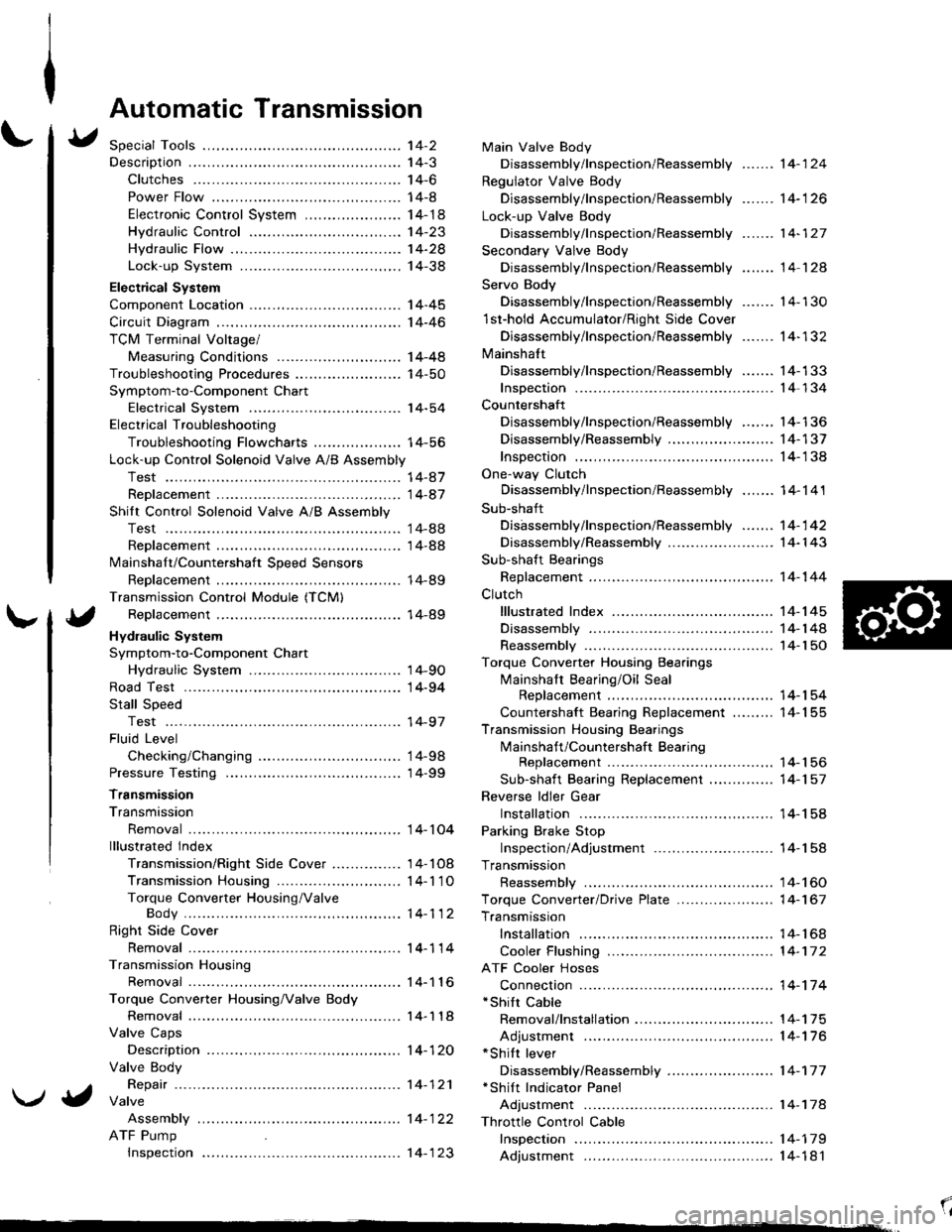
Automatic Transmission
Special Tools ................ '14-2
Descraption .................... 14-3
Clutches ............ ...... 14-6
Power Flow ..,........... 14-8
Electronic Control System ..................... 1 4-1 8
Hydraulic Control ...... 14-23
Hydraulic Flow .........- 14-28
Lock-up System ........ 14-38
Electrical System
Component Location -................................ 1 4-45
Circuit Diagram ............. 14-46
TCM Terminal Voltage/
Measuring Conditions ......,.................... 1 4-48
Troubleshooting Procedures .. . ... ........ ...... ... 14-50
Symptom-to-Component Chart
Electrical System ...... 14-54
Electrical Troubleshooting
Troubleshooting Flowcharts .......... ... ...,.. 14-56
Lock-up Control Solenoid Valve A/B Assembly
Test .................. ...... 14-A7
Replacement ............. 14-a7
Shilt Control Solenoid Valve A/B Assembly
Test .................. ...... '14-88
Replacement .,..,........ 14-88
lvlainshaf t/Countershaft Speed Sensors
Replacement ....-......,. 14-89
Transmission Control Module (TCM)
Replacement ............. 14-89
Hydraulic System
Symptom-to-Component Chart
Hydraulic System ...... 14-90
Road Test ,................... 14-94
Stall Speed
Test .................. ...... 14-97
Fluid Level
Checking/Changing .... 14-98
Pressure Testing ........... 14-99
Transmission
Transmission
Removal ............. ...... 14-10�4
lllustrated lndex
Transmission/Right Side Cover ............... 1 4-1 08
Transmission Housin9 ................,..,....... 1 4-1'1 O
Torque Converter Housing/ValveBody .................. .. 14-112
Right Side Cover
Removal ............. ...... 14-114
Transmission Housing
Removal ............. ...... 14-1 l6
Torque Converter Housing/Valve Body
Removal ............. ...... l4-1 18
Valve Caps
Description ...........-... 14-120
Valve Body
Repair ................ ...... 14-12'l
Valve
Assembly
ATF Pump
Inspeclton
Main Valve Body
Disassembly/lnspection/Reassembly
Regulator Valve Body
Disassembly/lnspection/Reassembly
Lock-up Valve Body
Disassembly/lnspection/Reassembly
Secondary Valve Body
Disassembly/lnspection/Reassembly
Servo Body
....... 14-124
....... 14-126
....... 14-127
....... 14 124
Disassembly/lnspection/Reassembly .......
1st-hold Accumulator/Right Side Cover
Disassembly/lnspection/Reassembly .......
Mainsha{t
14-130
14-132
Disassembly/lnspection/Reassembly ....... 14-133
Inspection ................. 14-134
Countershaft
Disassembly/lnspection/Reassembly,..,.., l4-136
Disassembly/Reassembly ..,...,..,.........,,.. 1 4-1 37
Inspection ......,...,..,... 14-138
One-way Clutch
Disassembly/lnspection/Reassembly ....,.. 14-141
Sub-shaft
Disassembly/lnspection/Reassembly ...,,..'14-142
Disassembly/Reassembly ....................... 1 4- l 43
Sub-shaft Bearings
Replacement ,..,,.,,..,.. 14-144
Clutch
lllustrated Index ................................... I 4-1 45
Disassembly ............. 14-144
Reassembly .............. 14-150
Torque Converter Housing Bearings
Mainshaft Bearing/Oil Seal
Replacement ......... 14-154
Countershaft Bearing Replacement ......... 1 4- 1 55
Transmission Housing Bearings
Mainshaft/Countershaft BearingReplacement ......,.. 14-'156
Sub-shaft Bearing Replacement .,............ 1 4-1 57
Reverse ldler Gear
Installation .........-..... 14-158
Parking Brake Stop
Inspection/Adjustment .......................... 1 4-1 58
Transmission
Reassembly .............. 14-160
Torque Converler/Drive Plate ..............,.,,.,, 1 4-1 67
Transmission
Installation ............... 14-168
Cooler Flushing ......... 14-172
ATF Cooler Hoses
Connection ,..,,,....,,.,, '14-'174
*shift cable
Removal/lnstallation . . .. .... ... .... ... .... .. . ... .. 14-'l75
Adjustment ,..,...,,,,.,, 14-'116*Shilt lever
Disassembly/Reassembly ....................... 1 4-'17 7'Shift Indicator Panel
Adjustment .............. 14-178
\l
)g
Page 531 of 1681
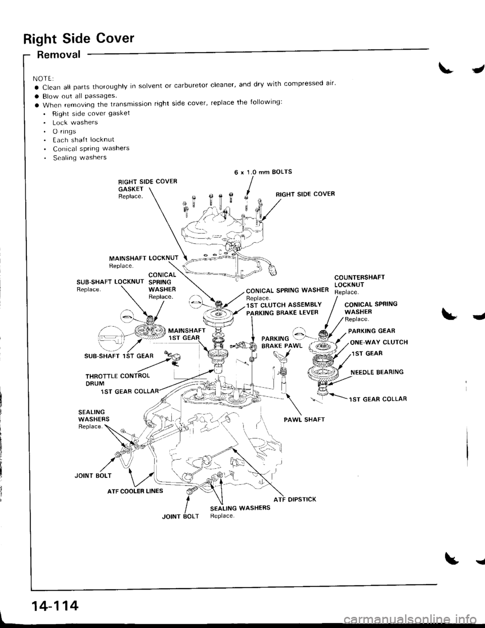
Right Side Cover
Removal
NOTE:
a Clean all parts thoroughly in solvent or carburetor cleaner' and dry with compressed alr'
a Blow out all Passages.
a When removing the transmission right side cover, replace the following:
. Right side cover gasket
. Lock washers. O rings. Each sha{t locknut
. Conical spring washers
. Sealing washers
RIGHT SIDE COVER
GASKETBeplace.
J
mm BOLTS6x1.0
,c
B,
MAINSHAFTReplace.LOCKNUT
RIGHT SIDE COVER
CONICAL SPRING WASHER
COUNTERSHAFTLOCKNUTSUB-SHAFT LOCKNUTReplace.
CONICALSPRINGWASHERReplace.Replace.1ST CLUTCH ASSEMBLY
PARKING BRAKE LEVERCONICALWASHERReplace.
SPRING
J
\-_7
SUB-SHAFT 1
PARKING GEAR
ONE-WAY CLUTCH
1ST GEAR
NEEOLE BEARING
1ST GEAR COLLAR
SEALINGWASHERSReplace.
JOINT BOLT
otPsTtcK
SEALING WASHERSReplace.
t
'::-Pf.a
THROTTLE CONTROLDRUM
1ST GEAB
ATF COOLER LINES
'. .)
14-114
I
Page 603 of 1681
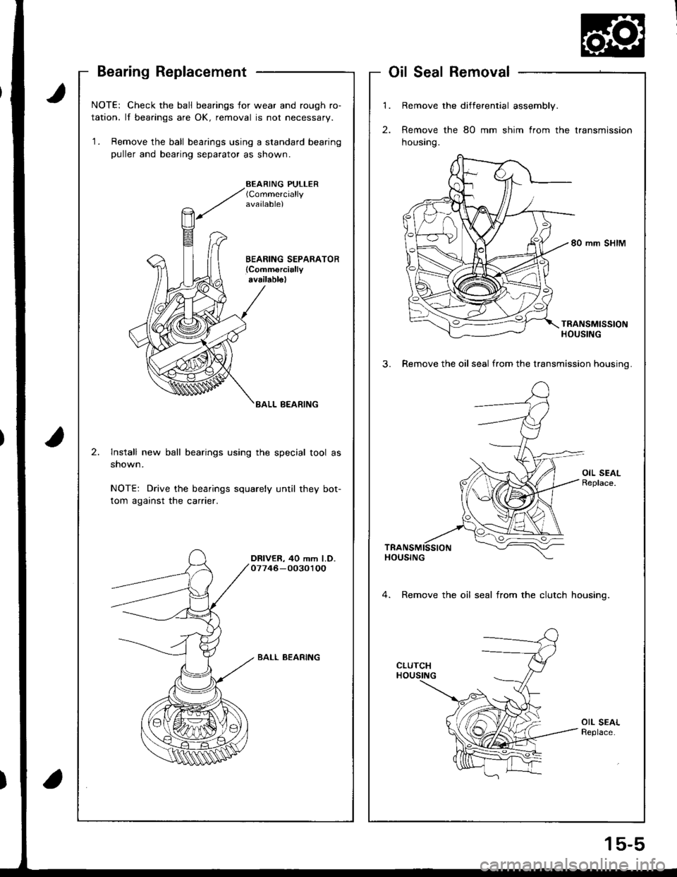
Bearing Replacement
t
a
NOTE: Check the ball bearings for wear and rough ro-
tation. lf bearings are OK, removal is not necessary.
'1. Remove the ball bearings using a standard bearing
puller and bearing separator as shown.
BEARING PULLER(Commercially
available)
BALL BEARING
2.lnstall new ball bearings using the special tool as
shown.
NOTE: Drive the bearings squarely until they bot-
tom against the carrier.
DRIVER, 40 mm l.D.07746-00301OO
BALL BEARING
't.
2.
Remove the differential assembly.
Remove the 80 mm shim from the transmission
housrng.
80 mm SHIM
TRANSMISSIONHOUSING
3. Remove the oil seal from the transmission housinq.
4. Remove the oil seal from the clutch housinq.
OIL SEALReplace.
SealRemoval
1s-5
Page 609 of 1681
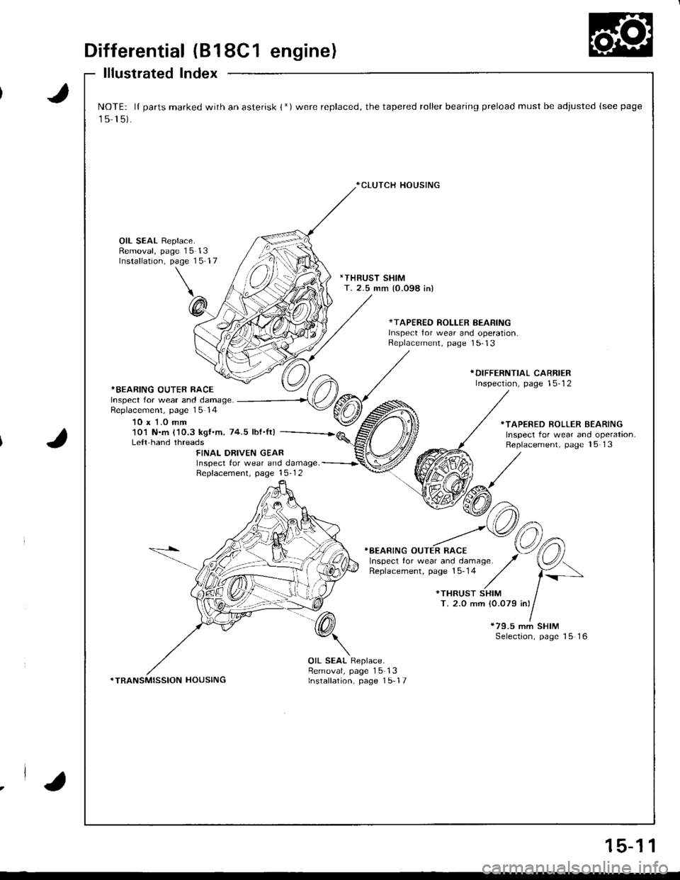
Differential (B18C1 engine)
lllustrated Index
J
J
NOTE: lI parts marked with an asterisk {*)were replaced, the tapered roller bearing preload must be adjusted (see page
15 15).
*CLUTCH HOUSING
OIL SEAL Replace.Removal, page 15 13Installation, page 15 17
*THRUST SHIMT. 2.5 mm {0.098 in)
*TAPERED ROLLER BEARINGlnsDect for wear and ooeration.Replacement, page 1 5-13
*BEARING OUTER RACEInspect for wear and damage.Replacemenl, page 15 14
10 x 1.0 mm
*DIFFERNTIAL CARRIERInspection, page 15-12
101 N.m {'10.3 kgf.m, 74.5 lbf.It)Le{t hand threads
*TAPERED ROLLER BEARINGInspect tor wear and operation.Replacement, page 15 13FINAL DRIVEN GEARInspect tor wear and damage. -----------r'
Repfacement. page 15-1 2
}BEARING OUTER RACE
*79.5 mm SHIMSelection, page 15 16
*TRANSMISSION HOUSING
OIL SEAL Replace.Removal, page 15-13Installation, page 1 5-17
.la
15-1 1
Page 611 of 1681
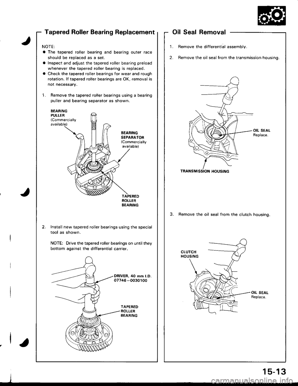
Tapered Roller Bearing ReplacementoilSealRemoval
1.
2.
Remove the difterential assembly.
Remove the oil seal lrom the transmission housing.
TRANSMISSION HOUSING
3. Remove the oil seal irom the clutch housino.
NOTE:
a The tapered roller bearing and bearing outer race
should be replaced as a set.
a Inspect and adjust the tapered roller bearing preload
whenever the tapered roller bearing is replaced.
a Check the tapered roller bearings for wear and rough
rotation. lI tapered roller bearings are OK, removal is
not necessary.
1. Remove the tapered roller bearings using a bearing
puller and bearing separator as shown.
BEARINGPULLER(Commercially
available)
BEARINGSEPARATOR(Commercially
available)
Install new tapered roller bearings using the special
tool as shown.
NOTE: Drive the tapered roller bearings on until they
bottom against the dillerential carrier.
DRIVER, 40 mm LD.07746 -OO30100
j
1 5-13
Page 1051 of 1681
J
Glutch Overhaul
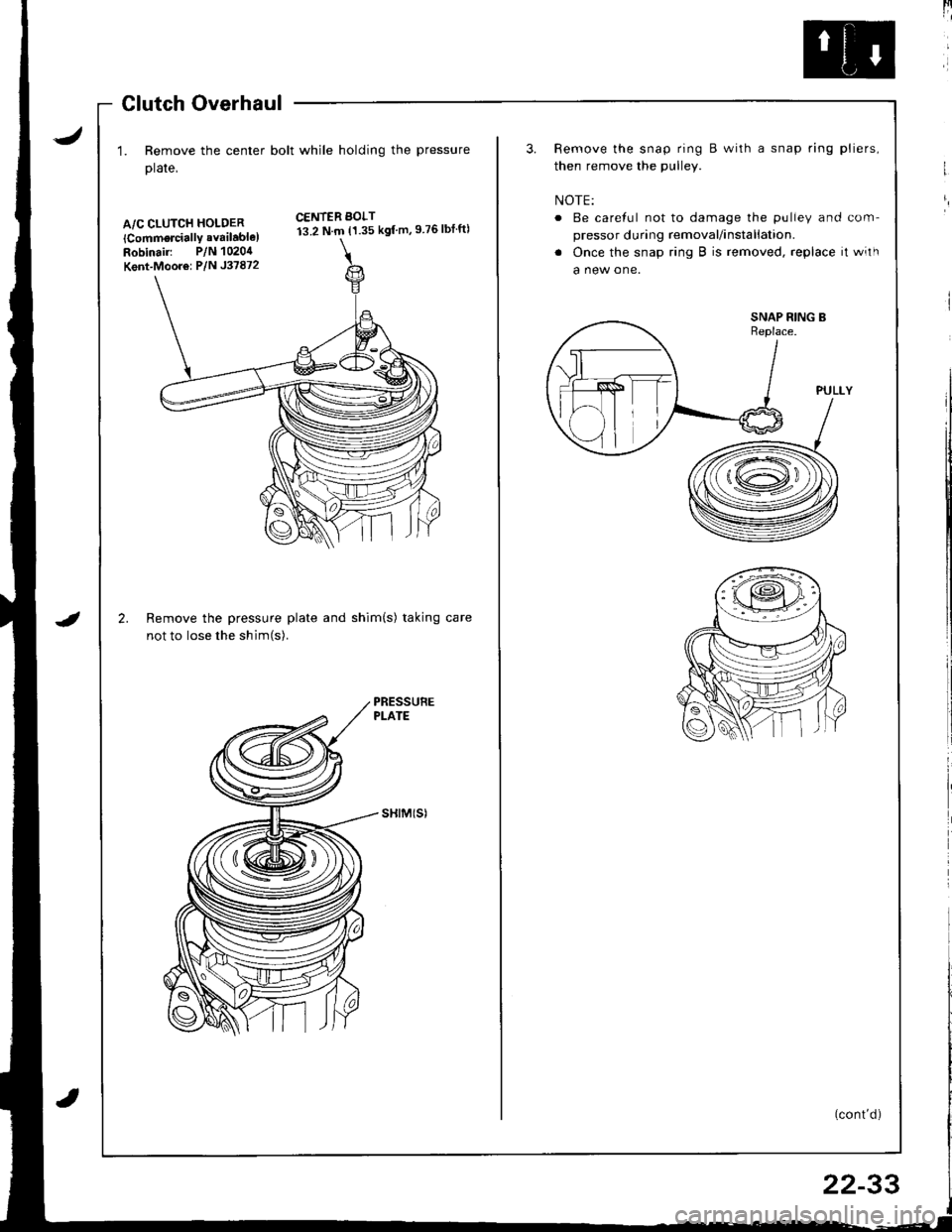
1. Remove the center bolt while holding the pressure
plate,
A/C CLUTCH HOLDER
lCommorcially available)Robinair: P/N 1020,1
Kent-Moor6: P/N J37872
2.
CENTER BOLT13.2 N.m {1.35 kgf m,9 76lbtft)
IRemove the pressure plate and shim(s) taking
not to lose the shim(s).
sHtM(sl
[4
3. Remove the snap ring B with a snap ring pliers,
then remove the pulley.
NOTE:
o Be careful not to damage the pulley and com-
pressor during removal/installation.
. Once the snap ring B is removed, replace it with
a new one.
(cont'd)
I
/ T-\vr= ...--.-
-ffitll---.\lr l,
\-l I .v
22-33
Page 1052 of 1681
Compressor
a
a
Clutch Overhaul (cont'dl
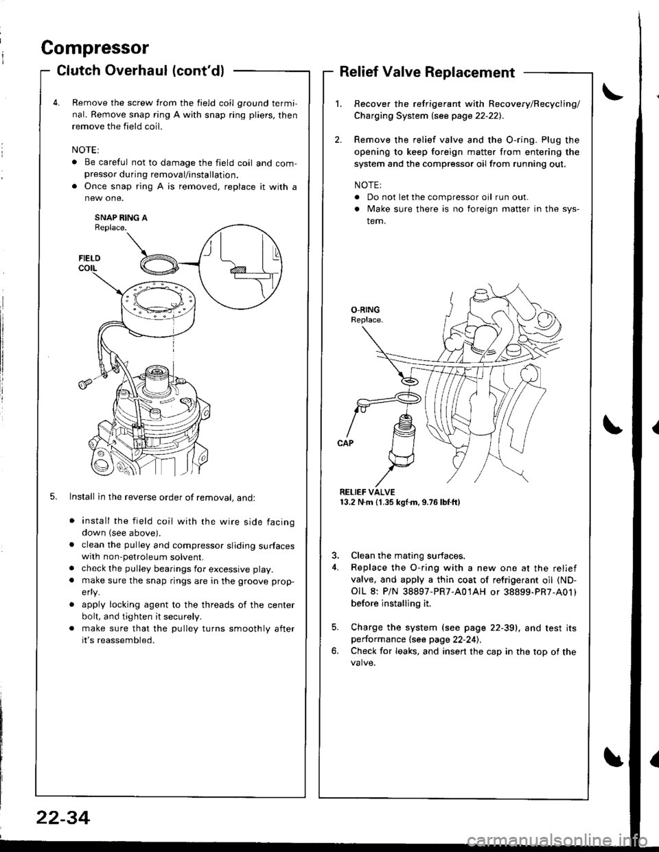
Remove the screw from the field coil ground termi,
nal. Remove snap ring A with snap ring pliers, then
remove the field coil.
. Be careful not to damage the field coil and com-presso. during removal/installation.
. Once snap ring A is removed, replace it with a
SNAP RING AReplace.
5. Install in the reverse order of removal, andl
install the field coil with the wire side facing
down (see above).
clean the pulley and compressor sliding surfaceswith non-petroleum solvent.
check the pulley bearings for excessive play.
make sure the snap rings are in the groove prop-
efly.
apply locking agent to the threads of the center
bolt, and tighten it securely.
make sure that the pulley turns smoothly after
it's reassembled.
Relief Valve Replacement
Recover the refrigerant with Recovery/Recycling/
Charging System lsee page 22-221.
Remove the relief valve and the O-ring. Plug the
opening to keep foreign matter from entering the
system and the compressor oil from running out,
NOTE:
. Do not let the compressor oil run out.
. Make sure there is no foreign matter in the sys-
tem.
RELIEF VALVE13.2 N.m (1.35 kgf.m,9.76lbtft)
3. Clean the mating surfaces.
4. Replace the O-ring with a new one at the relief
valve, and apply a thin coat of refrigerant oil (ND-
OIL 8: P/N 38897-PR7-A01AH or 38899-PR7-A01)
before installing it.
5. Charge the system (see page 22-39), and test itsperformance (see page 22-241.
6. Check for leaks, and insert the cap in the top of the
FIELD
t\I lu
B _t_:---\-lr
\,/
22-34