lock HONDA INTEGRA 1998 4.G Workshop Manual
[x] Cancel search | Manufacturer: HONDA, Model Year: 1998, Model line: INTEGRA, Model: HONDA INTEGRA 1998 4.GPages: 1681, PDF Size: 54.22 MB
Page 36 of 1681
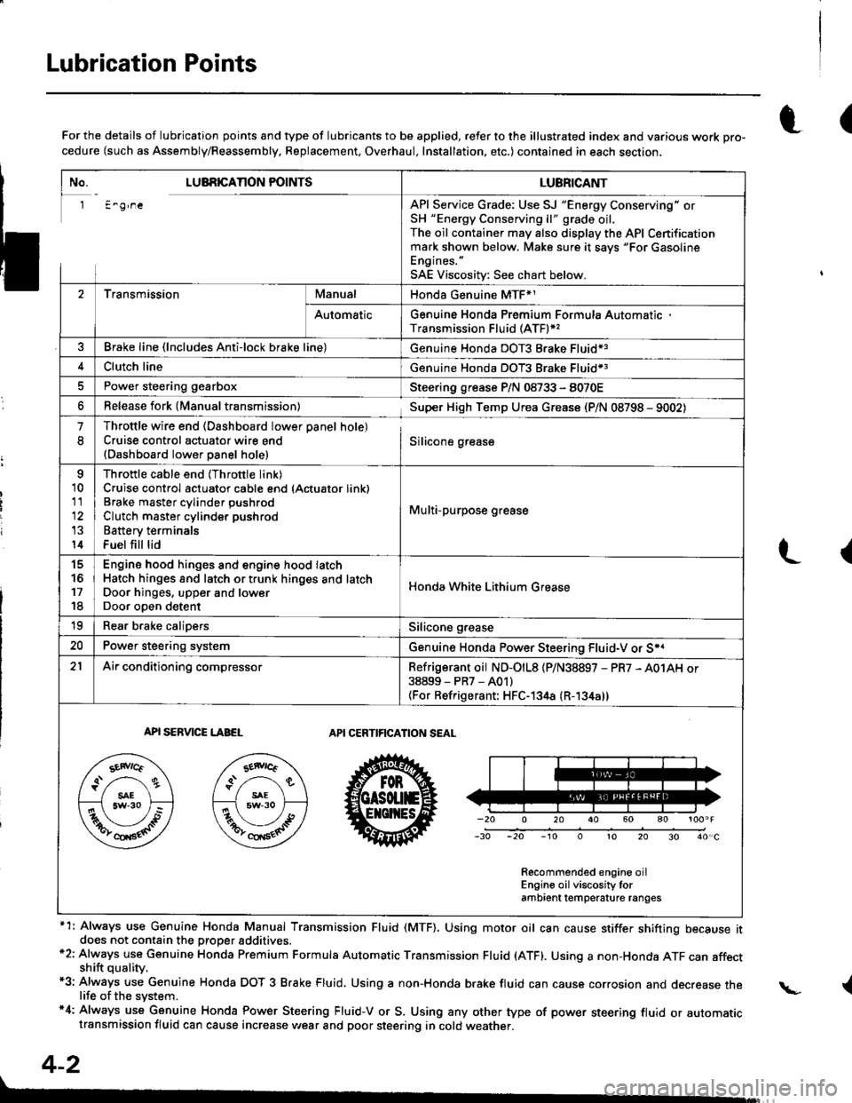
Lubrication Points
No. LUBRICAnON POINTSLUBRICANT
1 E^g,neAPI Service Grade: Use SJ "Energy Conserving" orSH "Energy Conserving ll" grade oil,The oil container may also display the API Certificationmark shown below. Make sure it savs "For GasolineEngines. "
SAE Viscositv: See chart below.
2TransmissionManualHonda Genuine MTF*1
AutomaticGenuine Honda Premium Formula AutomaticTransmission Fluid (ATF)*,
Brake line (lncludes Anti-lock brake line)Genuine Honda DOT3 Brake Fluid13
Clutch lineGenuine Honda DOT3 Brake Fluid*3
Power steering gearboxSteering grease P/N 08733 - 8070E
Release fork lManual transmission)Sup€r High Temp Urea Grease (P/N 08798 - 9002)
1
8
Throttle wire end (Dashboard lower oanel hole)Cruise control actuator wire end(Dashboard lower Danel hole)Silicone grease
o
10
11
14
Throttle cable end (Throttle link)Cruise control actuator cable end (Actuator link)Brake master cvlinder oushrodClutch master cylinder pushrod
Battery terminals
Fuel fill lid
Multi-purpose grease
to
17
18
Engin6 hood hinges and engine hood latchHatch hinges 8od latch or trunk hinges and latchDoor hjnges, upper and lowerDoor ooen detent
Honda White Lithium Grease
19Rear b.ake calipersSilicone grease
20Power steering systemGenuine Honda Power Steering Fluid-V or S*.
21Ai|' conditioning compressorRefrigerant oii ND-O|L8 {P/N38897 - PR7 - A01AH or38899-PR7-A01)(For Refrigerant: HFC-134a (R- 134a))
API SERVICE LABELAPI CERTIFICATION SEAL
Recommended engine oilEngin€ oil viscosity lorambrent lemperature ranges
r(For the details of lubrication points and type of lubricants to be applied, refer to the illustrated index and various work Dro-cedure (such as Assembly/Reassembly, Replacement, Overhaul, Installation. etc.) contained in each section,
*1: Always use Genuine Honda Manual Transmission Fluid (MTF). Using motor oil can cause stiffer shifting because itdoes not contain the proper addtuves.*2: Always use Genuine Honda Premium Formula Automatic Transmission Fluid (ATF). Using a non-Honda ATF can affectshift quality.*3: Always use Genuine Honda DOT 3 B.ake Fluid, Using a non-Honda brake fluid can cause corrosion and decrease thelife of the system.'4: Always use Genuine Honda Power Steering Fluid-V or S. Using any other type of power steering fluid or automatictransmission fluid can cause increase v,/ear and poor steering in cold weather.
L(
{
4-2
Page 37 of 1681
@at
at
@
@@
I
)
qfl-j__,n
til
* il/ .
\-_-.- _
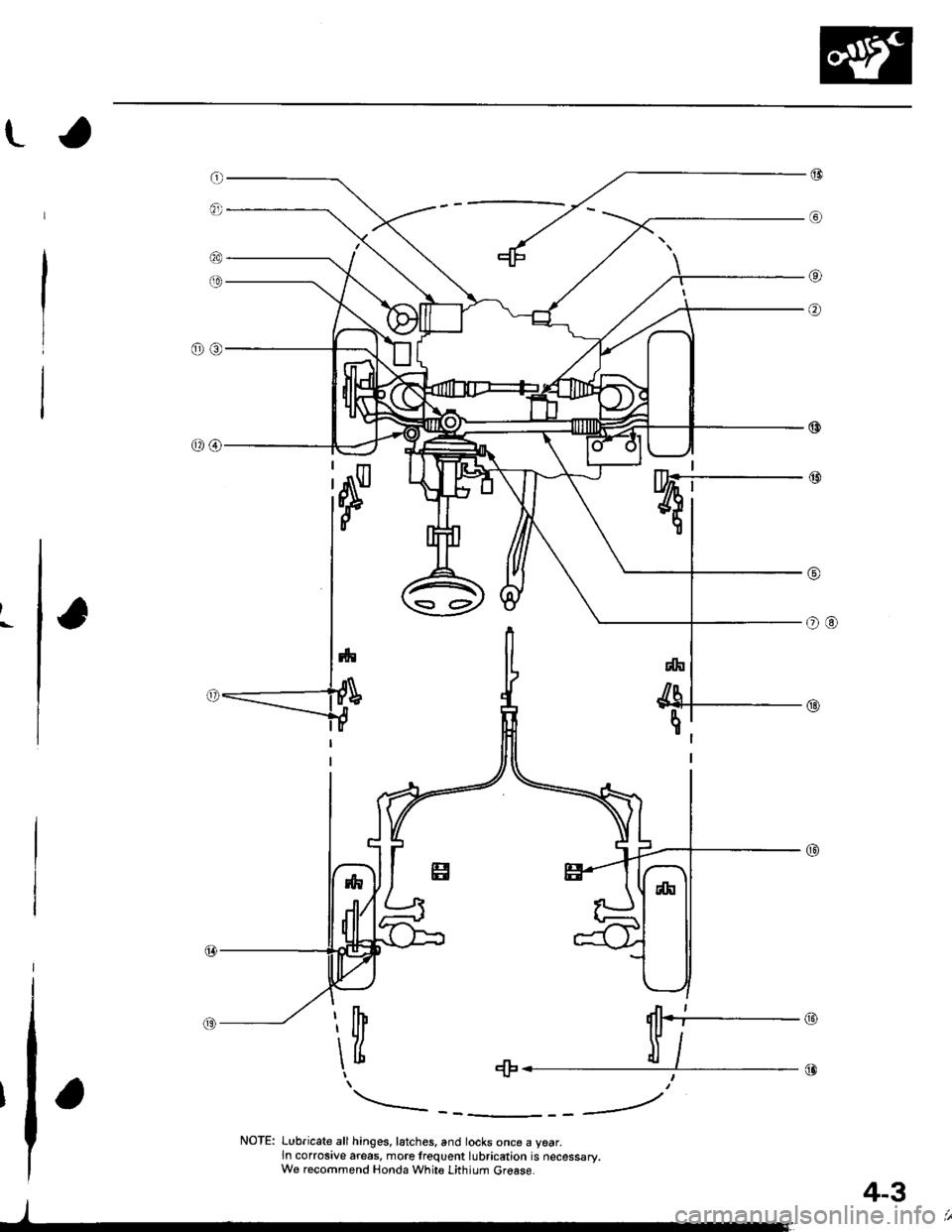
NOTE: Lubricate all hinges. latches, and locks once a year.ln corrosive areas, more frequent lubrication is necessary.We recommend Honda White Lithium Grease.
4-3
Page 42 of 1681
ra
Engine
Engine Removal/lnstallation ............. 5-1
Cylinder Head/Valve Train ............... 6-1
Engine Block ......... ........7-1
Engine Lubrication .........8-1
Intake Manifold/Exhaust System ...... 9-1
Cooling ....... 10-1
Page 51 of 1681
7
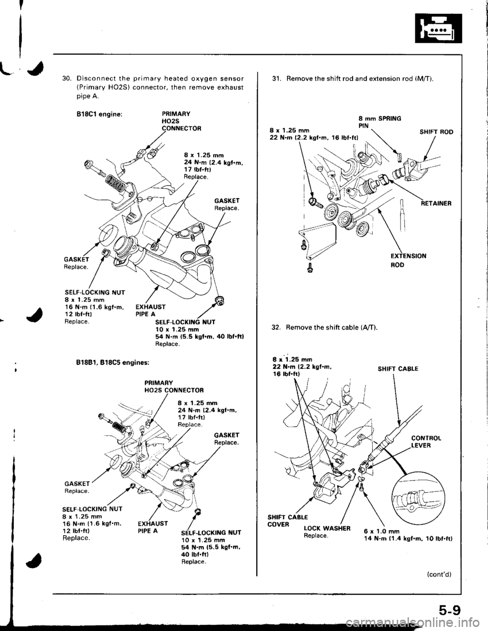
30.Disconnect the primary heated oxygen sensor(Primary HO2S) connector, then remove exhaust
pipe A.
818C1 engine:PRIMARYHO2S
8 x 1.25 mm24 N.m 12.4 kgl.m.t7 rbt.fttReplace.
GASKETReplace.
Replace.
SELF-LOCKING I{UT8 r 1.25 mm16 N.m (1 .6 kgf .m,
12 tbt.frtBeplace.
EXHAUSTPIPE A
NUT10 x 1.25 mm54 N.m {5.5 kgt'.n, tlo lbt.ft}Replace.
81881, 818C5 engines:
PRIMARYHO25 CONNECTOF
GASKETReplace.
GASKETReplace.
S€LF.LOCKING NUT
8 x 1.25 mm16 N.m (1.6 kgf'm,12 tbt.fr)Replace.f{UT10 x 1.25 mm54 N.m {5.5 kgf'm,40 lbf.ftlReplace.
8 x 1.25 mm24 N.m (2.4 kgt.m,17 lbf.frlReplace.
31. Remove the shift rod and extension rod {Mff).
8 x 1.25 mm22 N'm 12.2 kgl.m, '16 lbt.ttl
32. Remove the shift cable (A,/T).
I x 1.25 mm22 N-l'. 12.2 kgl.m,16 lbf.frl
SHIFT CABLE
CONTROLLEVER
6 x 'l.O mm14 N.m {1.4 kgf.m, 10 lbt.ft}
SHIFT ROD
RETAINER
SHIFT CABLE
LOCK WASHER
{cont'd)
COVER
5-9
Page 66 of 1681
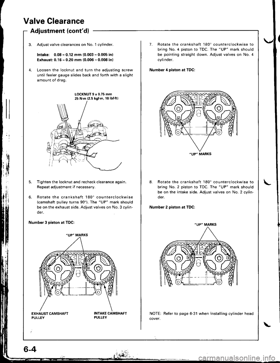
Valve Clearance
Adjustment (cont'dl
Adjust valve clearances on No. 1 cylinder.
Intske: 0.08 - 0.12 mm (0.003 - 0.005 inl
Exhaust: 0.15 - 0.20 mm (0.006 - 0.008 inl
Loosen the locknut and turn the adjusting screw
until feeler gauge slides back and forth with a slight
amount of drag.
7. Rotate the crankshaft 180' counterclockwise to
bring No. 4 piston to TDC. The "UP" mark should
be pointing straight down. Adjust valves on No. 4
cylinder.
Number 4 piston at TDC:
LOCKNUT9x0.75mm25 N.m {2.5 kgl.m, 18lbtft}
Tighten the locknut and recheck clearance again,
Repeat adjustment if necessary.
Rotate the crankshaft 180' counterclockwise(camshaft pulley turns 90'). The "UP" mark should
be on the exhaust side. Adjust valves on No,3 cylin-
der.
8. Rotate the crankshaft 180' counterclockwise to
bring No. 2 piston to TDC. The "UP" mark should
be on the intake side. Adjust valves on No. 2 cylin-
der.
Number 2 piston at TDC:
Number 3 Diston at TDC:
NOTE: Refer to page 6-31 when installing cylinder head
cover.
"UP" MARKS
"UP" MARKS
"UP" MARKS
Page 71 of 1681
\-a
I
I
{
. 6-9
Timing Belt
Inspection
1.Remove the cylinder head cover.
o Refer to page 6-33 when installing.
Inspect the timing belt for cracks and oil or coolant
soal(n9.
NOTE:
. Replace the belt if oil or coolant soaked.
. Remove any oil or solvent that gets on the belt.
2.
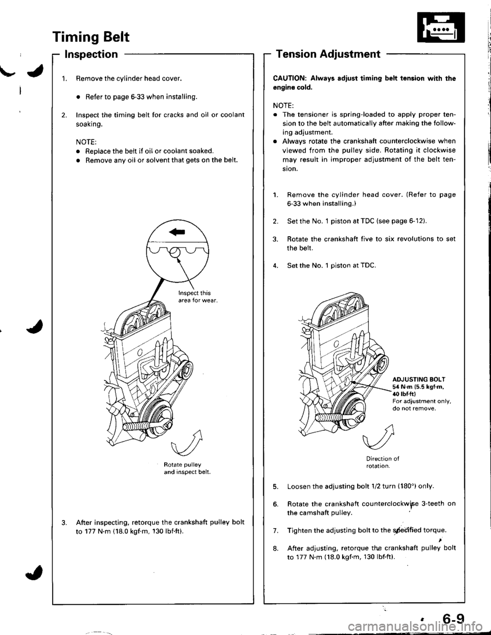
Rotate pulley
and inspect belt.
After inspecting. retorque the crankshaft pulley bolt
to 177 N'm (18.0 kgf.m, 130 lbnft).
CAUTION: Always adiust iiming belt lension with the
engin€ cold.
NOTE:
. The tensioner is spring-loaded to apply proper ten-
sion to the belt automatically after making the follow-
ing adjustment.
. Alwavs rotate the crankshaft counterclockwise when
viewed from the pulley side. Rotating it clockwise
may result in improper adjustment of the belt ten-
ston.
Remove the cylinder head cover. (Refer to page
6-33 when installing.)
Set the No. I piston at TDC (see page 6-12).
Rotate the crankshaft five to six revolutions to set
the belt.
Set the No. 1 piston at TDC.
1.
2.
ADJUSTING BOLT54 N.m (5.5 kgf.m,{0 rbr.fttFor adjustment only,do not remove,
7.
8.
Direction ofrotation.
Loosen the adjusting bolt 1/2 turn (180') only.
Rotate the crankshaft counterclockwiFe 3-teeth on
the camshaft pulley
Tighten the adjusting bolt to the qdebified torque.
After adjusting. retorque the crankshaft pulley bolt
to 177 N.m {18.0 kgf.m, 130 lbf.ftl.
Page 82 of 1681
Gylinder Head
Removallcont'd)
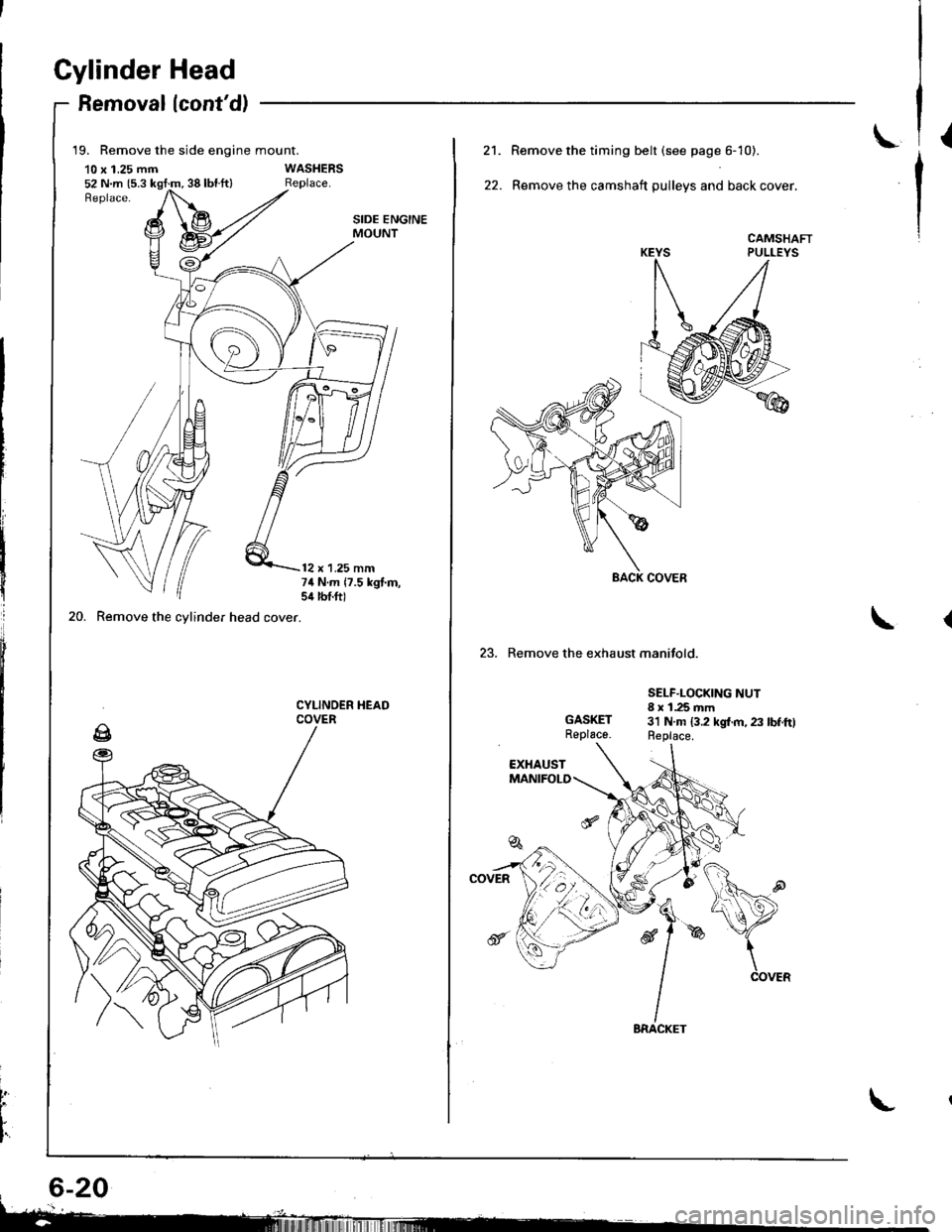
19. Remove the side engine mount.
10 x 1.25 mm52 N.m {5.3 kgt:m, 38 lbl.ft}
20. Remove the cylinder head cover.
SIDE ENGINEMOUNT
12 x 1.25 mm74 N.m 17.5 kgt.m,sil lbtft)
CYLINOER HEADCOVER
t
L
I'
L21.
22.
Remove the timing belt (see page 6- 10).
Remove the camshaft pulleys and back cover.
CAMSHAFTPULLEYS
23. Remove the exhaust manifold.
GASKETReplace.
SELF.LOCKING NUT8 x 1.25 mm3'l N.m 13.2 kgl.m, 23 lbf.ftlReplace.
Page 92 of 1681
Cylinder Head
Wapage
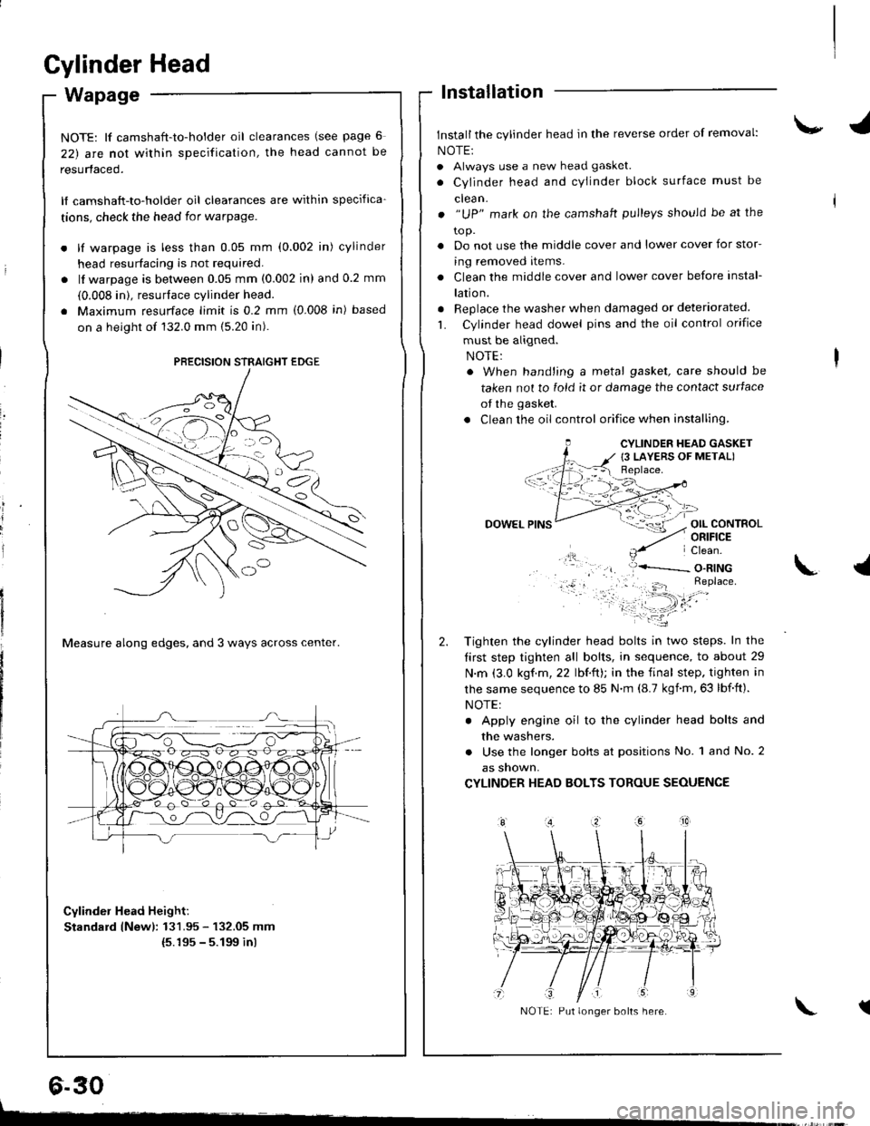
NOTE: lf camshaft-to-holder oil clearances (see page 6
22) arc nol within specification, the head cannot be
resurfaced.
lf camshaft-to-holder oil clearances are within specifica-
tions, check the head for warpage.
lf warpage is less than 0.05 mm (0.002 in) cylinder
head resurfacing is not required.
lf warpage is between 0.05 mm (0.002 in) and 0.2 mm
(0.008 in). resurface cylinder head.
Maximum resurface limit is 0.2 mm (0.008 in) based
on a height of 132.0 mm (5.20 in).
Measure along edges, and 3 ways across center.
Cylinder Head Height:
Standard lNewl: 131.95 - 132.05 mm(5.195 - 5.199 inl
lnstallation
Install the cylinder head in the reverse order of removal:
NOTE:
. Always use a new head gasket.
. Cylinder head and cYlinder block surface must be
clean.
. "UP" mark on the camshaft pulleys should be at the
to p.
. Do not use the middle cover and lower cover for stor-
ing removed items.
. Clean the middle cover and lower cover before instal-
lation.
. Replace the washer when damaged or deteriorated
L Cylinder head dowel pins and the oil control orifice
must be aligned.
. When hand'ing a metal gasket, care should be
taken not to fold it or damage the contact surface
of the gasket.
. Clean the oil control orifice when installing,
OIL CONTROLORIFICE
PRECISION STRAIGHT EDGE
6.30
CYLINDER HEAD GASKET
{3 LAYERS OF METAL)
DOWEL
Tighten the cylinder head bolts in two steps. In the
tirst step tighten all bolts, in sequence, to about 29
N.m (3.0 kgf.m,22 lbf.ft); in the final step. tighten in
lhe same sequence to 85 N.m (8.7 kgnm,63 lbf.ft).
NOTE:
. Apply engine oil to the cylinder head bolts and
the washers.
. Use the longer bolts at positions No. 1 and No. 2
as snown,
CYLINDER HEAD BOLTS TOROUE SEOUENCE
\.l
tNOTE: Put longer bolts here.
t-
Page 93 of 1681
\-
L
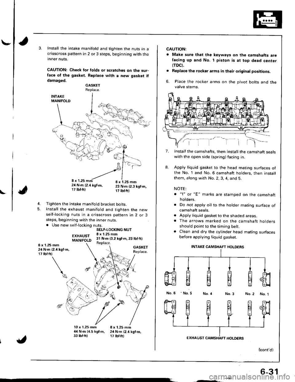
Install the intake manifold and tighten the nuts in acflsscross pattern in 2 or 3 steps. beginning with theinner nuts.
CAUTION: Check lor folds or scratches on the sur-face ol the gasket. Replace with a new gasket ildamaged.GASKETReplace.
INTAKEMANIFOLD
4. Tighten the intake manifold bracket bolts.5. Install the exhaust maniiold and tighten the newself-locking nuts in a crisscross pattern in 2 or 3steps, beginning with the inner nuts.. Use new self-locking nuts.
EXHAUSTMANIFOLD
GASKETReplace.
4
10 x 1.25 mm 8 x 1.25 mm4,{ N.rn 14.5 kgf.m, 24 N.m {2.4 kgtm,33 tbf.ftl '17 tbf.ft)
SELF.LOCKING NUT8 x 1.25 mm31 N.m (3.2 kgt m,23 lbf.ft)Replace.1 .25 mmN.m {2.4 kg{.m,rbrftt
\q
8x2417
",', r, ^-'-"-!,1,,,';-21N.m l2.1kglm, 23 N.m (2.3 ksf.m,17lbf.ftl 17 tbf.ftr
6-31
CAUTION:
. Make sure that the keyways on the camshafts aretacing up and No. 1 piston is at top dead cenier
tTDCt.. Replacethe rocker arms in their original positions.
6. Place the rocker arms on the pivot bolts and thevalve stems.
7.
8.
Install the camshafts, then install the camshaft sealswith the open side (spring) facing in.
Apply liquid gasket to the head mating surfaces otthe No. 1 and No. 6 camshaft holders, then installthem, along with No.2,3, 4, and 5.
NOTE:
. "l" or "E' marks are stamped on the camshaftholders.
. Do not apply oil to the holder mating surface ofcamshaft seals.. Apply liquid gasket to the shaded areas.. The arrows marked on the camshaft holdersshould point to the timing belt.. Clean and dry the cylinder head mating surfacesbefore applying liquid gasket.
INTAKE CAMSHAFT HOLDERS
No.6 No.5No.4No.3 No.2 No. 1
{cont'd)
Page 147 of 1681
I
lllustrated Index
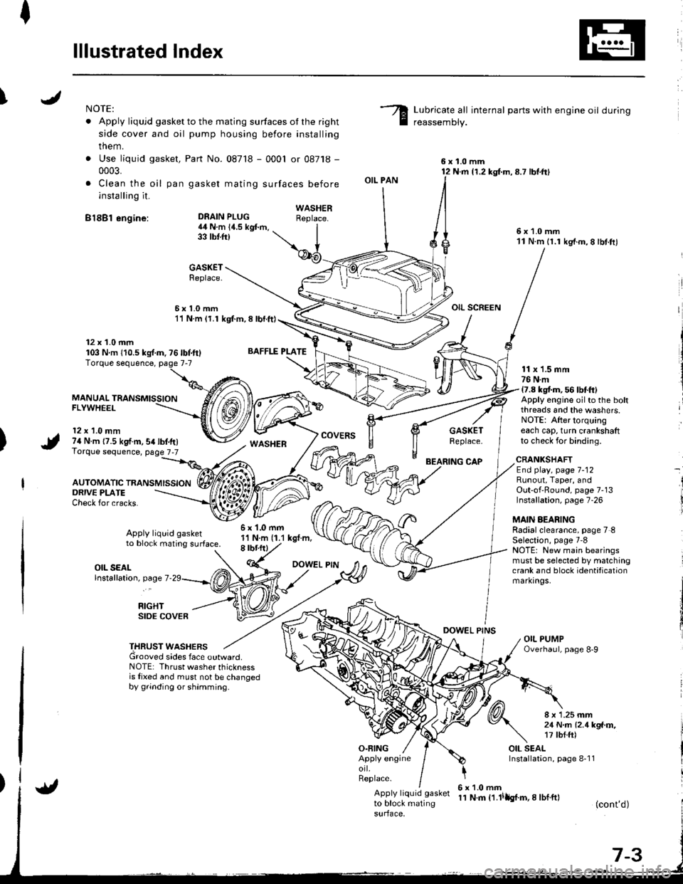
INOTE:
. Apply liqujd gasket to the mating surfaces ot the right
side cover and oil pump housing before installing
them.
. Use liquid gasket,
0003.
. Clea n the oil pan
installing it.
B18Bl engine:
Part No. 087'18 - 0001 or 08718 -
gasket mating surfaces before
Lubricate all internal parts with engine oil during
reassemDly.
6x1.0mm12 N.m {1.2 kg{.m,8.7 lbt.ft}
6x1.0mm11 N.m 11.1 kg'f.m,8 lbt.ftl
OIL SCREEN
DEAIN PLUG4il N.m 14.5 kgt m,33 tbtft)
BAFFLE PLATE
6x1.0mm1'l N.m (1.1 kgt.m,8 rbr.ftl
OIL PAN
O.FING
CAP
DOWEL PINS
WASHERReplace.
GASKETReplace.
6x1.0mm11 N.m (1.1 kgl.m, 8 lbl.ft)
12 x 1.0 mm103 Nm 110.5ks{.m,76lbf.ft}
MANUAL TRANSMISSIONFLYWHEEL
12 x 1.0 mm74 N.m 17.5 kgf.m,54lbf.tr)Torque sequence, page 7-7
AUTOMATIC TRANSMISSION
WASHERcovERsGASKETReplace.
11 x 1.5 mm76 N.m17.8 kgt m, 56 lbtft)Apply engine oilto the boltthreads and the washers.NOTE: After torquingeach cap, turn crankshaftto check for binding.
ORIVE PLATECheck for cracks.
Apply liquid gasketto block mating surface.
CRANKSHAFTEnd play, page 7-12Runout, Taper, andOut-of'Round, page 7-13Installation, page 7-26
MAIN AEARINGRadialclearance, page 7 8Selection, page 7'8NOTE: New main bearingsmust be selected by matchingcrank and block identificationmarkrngs.
I
i
OIL SEALlnstallation, page 7
RIGHTSIDE COVER
THRUST WASHERSGrooved sides face outward.NOTE: Thrust washer thicknessis fixed and must not be changedby grinding or shamming.
8 x 1.25 mm21 N..n l2.1kga'r,�,17 tbf.ft)
OIL SEALInstallation, page 8-1 1Apply engineorl.Replace.
Apply liquid gasket
to block matingsurface,
6x1.0mm11 N.m t1.lilh{.m,I lbf.ft}(cont'd)