Power windows HONDA INTEGRA 1998 4.G User Guide
[x] Cancel search | Manufacturer: HONDA, Model Year: 1998, Model line: INTEGRA, Model: HONDA INTEGRA 1998 4.GPages: 1681, PDF Size: 54.22 MB
Page 1534 of 1681
r-T--------.lUNDER.
I t FUSE46 IHOODi PovrER iFUSEt! I glDow ! RELAYI I* lBoxL_ rfa __ ___ ___J DtlOrO 2l
'l( ?i:L,,wHr/BLU IN C4396 A PHoro 62
:;I
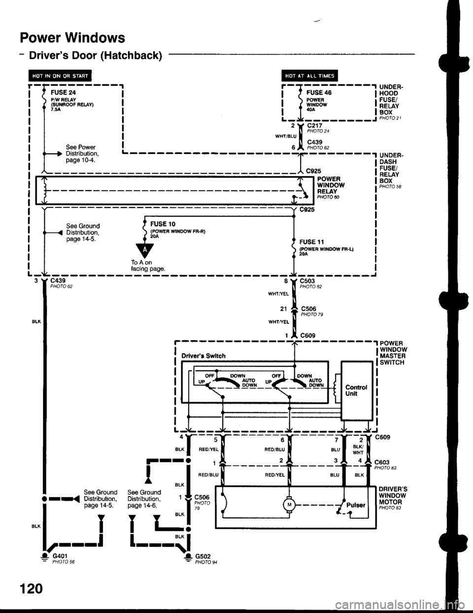
Power Windows
- Driver's Door (Hatchback)
I
Jffi;-----
f
l*n"oo"""-n
I
I ,"" ro*",
f4 Distribution,
L_il"_j___
UNDER-DASHFUSE/RELAYBOX
_t;'-----tPOWERwtNDowBELAY
See GroundD islribution,page 1+5.
c925
FUSE 11{POWEn wlt{DOW rF-I)
c439PHO|O 62c503PHOTO 62
cs06
c609
POWERwtNDowMASTERswtTcH
--------1
Drive/8 Swllch
2BLr./
4
7
BLU
3c603
DRIVER'SwtNDowMOTOR
See GroundDistribution,page 14-5.
Y
I
-l
lrr{
".* I
lllt--
120
Page 1536 of 1681
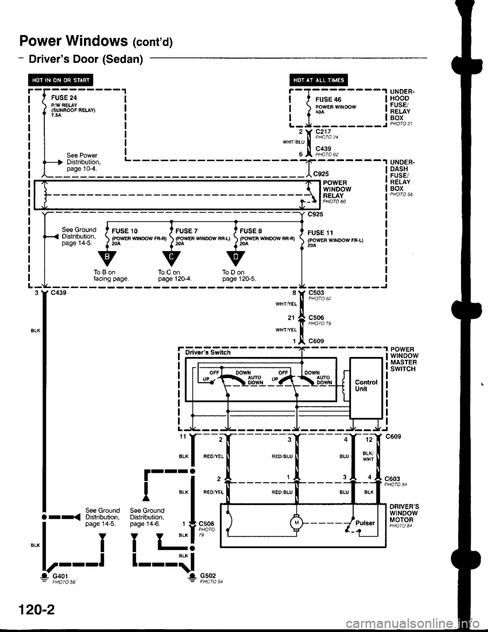
Power Windows (cont'd)
- Driver's Door (Sedan)
See GroundDistribution,page 14-5.
FUSE 10(POWEF Wrf{rOW rB€)20A
FUSE 7(FOWEA WTNOOW FB-L)204
FUSE 8{FOWEB WTNOOW Fi.F)
UNDER.HOODFUSE/RELAYBOX
UNDER-DASH
RELAYBOX
POWERwtNDowMASTEBswrTcH
i-l;;;----l
t-l::-::---i, t( Fi;/.,"*"'"1,!,
F,i';.,
BLIq
IL
-rffi;-----
f
*"oo'"'-'
I
| ,"" ro'n",
l----t Distribution,
L_i1"1'l____f;-----lPOWERwlt'IDOWRELAY
c925
FUSE 11(POWER WINDOW FF-L)204
--------Jc503
c506
toLjontacing page.touonpage 12G4.ToDonpage 120"5.
r-
l-
I
_t_
::,:1[
c609
l-fiu?'isiii-"r'--
8LU
.__,
FEO,^VEL
RED]YEI
.."^ [;;,;io I"t.
G502PHATO 91
L1
""I
ra
""1
.1.
"*rt
ra
\1,
ALK
III
BLK
Ind)n,3. 1
Y BLK
l-BLK
IIl.
1
I
See GroundDistribution,Daoe 14-6.
See GIlDistrib!page 1,
I
l--l
I
c603
See GroundDistribution,page 14'5.
Y
I
DRIVER'SwtNDowMOTORc506Orr{
".* I
llt--
-r- u4ul
I
120-2
Page 1538 of 1681
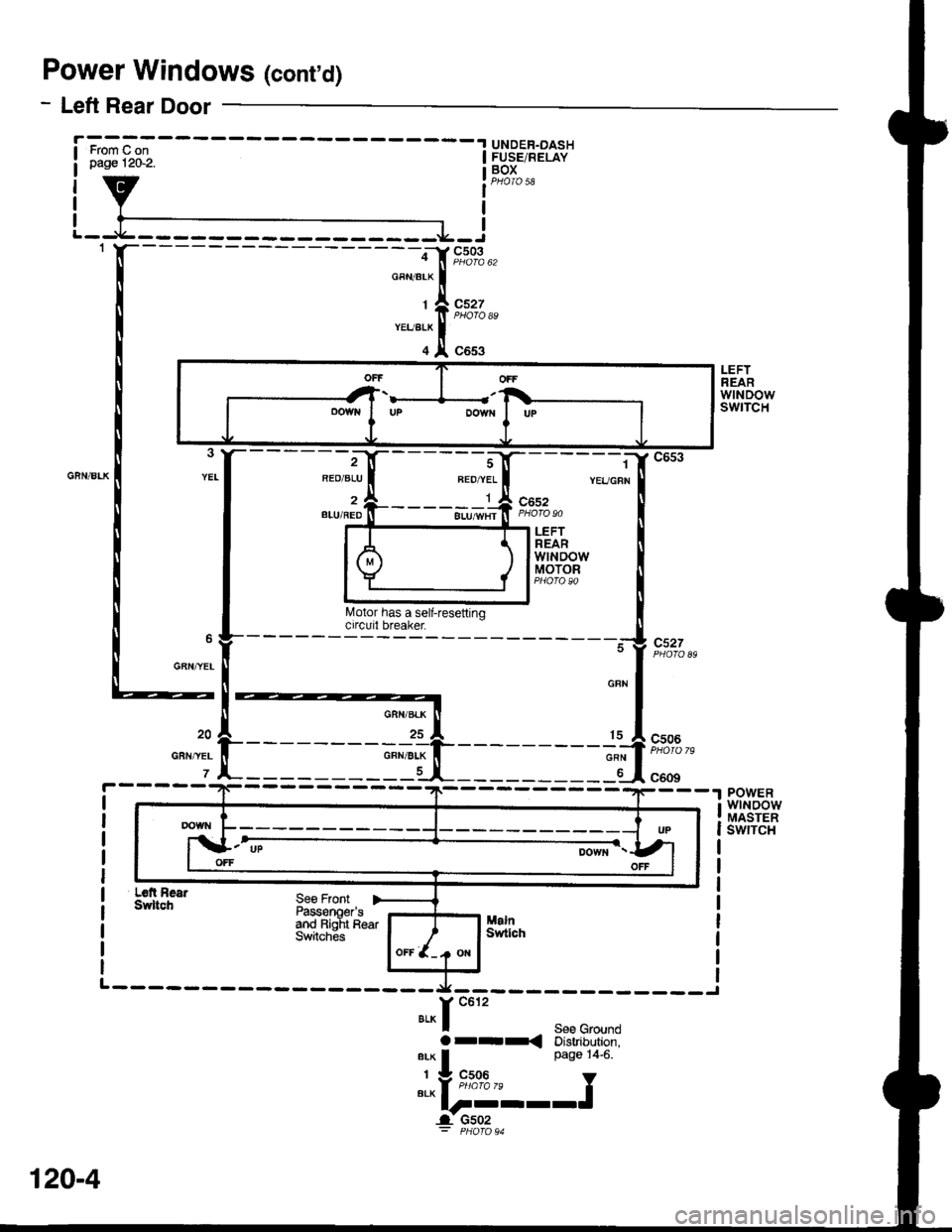
Power Windows (cont'd)
- Left Rear Door
UNDER-DASHFUSE/RELAYBOX
I
cs03
c527
c653ffi
LEFTREARwtNDowswtTcH
REO/ALU
l
2BLU/REDc652
c527
LEFTREARwtNDowMOTOR
GAN,YEL
c506
c609POWERwtNoowMASTERswrTcH
Ldt AearSwltchSee FrontPassonoer'sand Bialt R€arSwitches
-.x---------- ____J
Y c612
BLK I See GroundOr-r< Distribution,arx I Page 14-6.
' v "c;0*," Y"t"l-----J
_l u5uz
OFFOFF
oowNDOWfIUP
120-4
Page 1540 of 1681
Power Windows (conrd)
- How the Circuit Works
CAUTION: You could iniure your arms, hands,
or fingers if you unintentionally switch the
driver's window to "automatic down,' while
working in that door with the power on. Discon-
nect the window switch connector or the battery
when working in the driver's door.
System Description
The operation of the power windows is controlled by
the main switch in the power window masler switch.
When the main switch is in OFF, only the driver's
door window can be opened or closed. With the main
switch ON, all windows can be opened or closed
either by switches in the master panel, or switches in
the doors. The driver's window switch also has an
automatic down mode which is tumed on by pushing
the switch down to its second position.
The power windows are driven by reversible motors.
Each motor is protected by a built-in circuit breaker.
lf the window switch is held on too long (with the
window obstructed, or after the window is fully up or
down), the circuit breaker opens the circuit. The
circuit breaker resels automaticallV as it cools.
Driver's Window
With the ignition switch in ON (tt), vottage isprovided to the coil ol the power window relay
through fuse 24. The contacts of the power window
relay close, and voltage is applied to the driver's
switch. When you push the power window master
switch to Uq voltage is applied to the driver's power
window motor. (The motor's ground path is backthrough the power window master switch.) The
driver's window motor then drives the window uo.
When you push the switch to DOWN, voltage ls
applied in the opposite direction and the motor
drives the window down.
Automatic Down (Driver's Window)
With the ignition switch in ON (tl), vottage is applied
to the coil of the power window relay. The contacts
of the power window relay close and voltage is
applied to the power window master switch. When
you push the driver's switch to the AUTO DOWN
position, voltage is applied through the drivels
switch to the driver's window motor. The control unit
receives pulses at the pulser input while the motor
is running. When the window is fully down, the
motor stops, and pulses are no longer generated by
the pulser. This is sensed by the control unit at thepulsBr input, and voltage is no longer applied to the
driver's window motor.
Passenger Windows
With the ignition switch in ON (tt), vottage is apptied
to the coil of the power window relay through fuse
24. The contacts of the power window relay then
close, applying voltage to the individual window
switches and the power window master switch. With
the master panel main switch ON, the passenger
windows can be operated from the individual
window switches or from the master Danel switches.
When you push the front passenger's window
switch to UR voltage is applied to the front
passenger's window motor. (The motor is grounded
through the contacts in the front passenger's window
switch and the power window master switch.) The
wndow moves up as long as you hold the switch in
lhe UP position. lf you push the switch to DOWN,
voltage is applied in the opposite direction io the
front passenger's window motor, and the window
moves down as long as you hold the switch in the
DOWN position. The window switches in the other
doors operate similarly.
When you push the front passenger's switch in the
master panel to UP, voltage is applied through the
front passengeas window switch contacts to the
front passenger's window motor (The motor is
grounded through the contacts in the front
passenger's window switch and the power window
master switch.) The window moves up as long asyou hold the switch in the UP position. lf you push
the switch to DOWN, voltage is applied in the
opposite direction to the front passenger's window
motor, and the window moves down as long as you
hold the switch in the DOWN position. The otherpassenger window switches in the master panel
operate similarly.
Refer to the Service Manual (Section 23, Electrical)
for specific tests or troubleshooting procedures.
120-6
Page 1632 of 1681
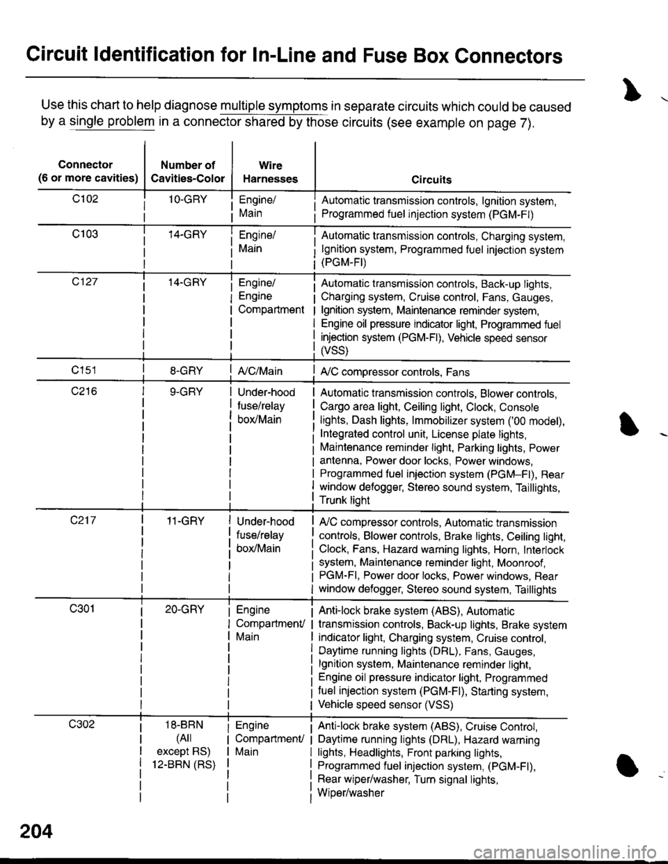
Circuit ldentification for In-Line and Fuse Box Connectors
Use this chart to help diagnose multiple symptoms in separate circuits which could be caused
by a single problem in a connector shared by those circuits (see example on page 7).
Connector
(6 or more cavities)
Number of
Cavities-Color
Wire
Harnesses
Engine/
Main
Engine/
Engine
Compartment
I Automatic transmission controls, lgnition system,
i Programmed fuel injection system (PGM-F|)
Automatic transmission controls, Charging system,
lgnition system, Programmed fuel injection system(PGM-FI)
Automatic transmission controls, Back-up lights,
Charging system, Cruise control, Fans, Gauges,
lgnition system, Maintenance reminder system,
Engine oil pressure indicator light, Programmed fuel
injection system (PGM-Fl), Vehicle speed sensor
ffss)
| {c/Main! A,/C compressor controls, Fans
Under-hood
fuse/relay
box/Main
Automatic transmission controls, Blower controls,
Cargo area light, Ceiling light, Clock, Console
lights, Dash lights, lmmobilizer system ('00 model),
Integrated control unit, License plate lights,
Maintenance reminder light, Parking lights, Power
antenna, Power door locks, Power windows,
Programmed fuel iniection system (PGM-Fl), Rear
window defogger, Stereo sound system, Taillights,
Trunk lioht
11-GRY
18-BBN
(4il
except BS)
12-BBN (RS)
Under-hood
fuse/relay
box/Main
Engine
CompartmenV
Main
Engine
CompartmenU
Main
lr,/C compressor controls, Automatic transmission
controls, Blower controls, Brake lights, Ceiling light,
Clock, Fans, Hazard warning lights, Horn, Interlock
system, Maintenance reminder light, Moonroof ,PGM-FI, Power door locks, Power windows, Rear
window defogger, Stereo sound system, Taillights
Anti-lock brake system (ABS), Automatic
transmission controls, Back-up lights, Brake system
indicator light, Charging system, Cruise control,
Daytime running lights (DRL), Fans, Gauges,
lgnition system, Maintenance reminder light,
Engine oil pressure indicator light, Programmed
tuel injection system (PGM-F|), Starting system,
Vehicle speed sensor (VSS)
Anti-lock brake system (ABS), Cruise Conkol,
Daytime running lights (DRL), Hazard warning
lights, Headlights, Front parking lights,
Programmed fuel injection system, (PGM-Fl),
Rear wiper/washer, Turn signal lights,
Wiper/washer
204
Page 1633 of 1681
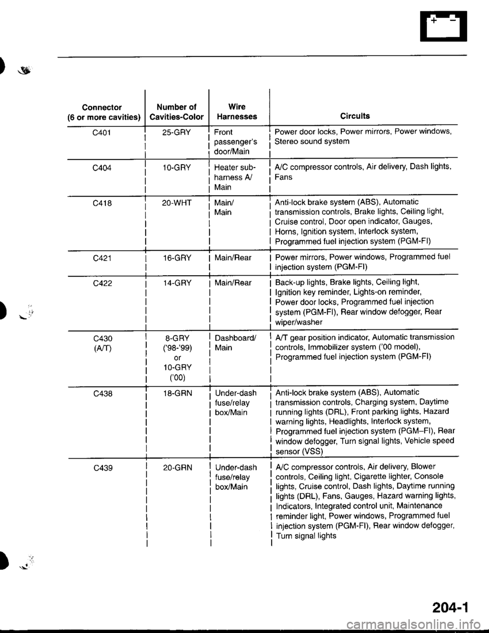
)ot
Connector
(6 or more cavities)
Number of
Cavities-Color
25-GRY
1O-GRY
Wire
Harnesses
Front
passenger's
door/Main
Heater sub-
harness A,/
Main
Circuits
Power door locks, Power mirrors, Power windows,
Stereo sound svstem
fuC compressor controls, Air delivery, Dash lights,
Fans
transmission controls, Brake lights, Ceiling light,
Cruise control, Door open indicator, Gauges,
Horns, lgnition system, Interlock system,
Programmed fuel injection system (PGM-Fl)
Main/
Main
Anti-lock brake system (ABS), Automatic
16.GRYMain/RearPower mirrors, Power windows, Programmed tuel
injection system (PGM-Fl)
14-GRYMain/RearBack-up lights, Brake lights, Ceiling light,
lgnition key reminder, Lights-on reminder,
Power door locks, Programmed fuel iniection
system (PGM-Fl), Rear window defogger, Rear
wiDer/washer) -io
tl
c430
(An)
8-GRY
(e8-'ee)
or
1O-GRY
(00)
18-GRN
Dashboard/
Main
Under-dash
fuse/relay
box/Main
A/T gear position indicator, Automatic transmission
controls, lmmobilizer system ('00 model),
Programmed fuel injection system (PGM-Fl)
Anti-lock brake system (ABS), Automatic
transmission controls, Charging system, Daytime
running lights (DBL), Front parking lights, Hazard
warning lights, Headlights, lnterlock system,
Programmed fuel injection system (PGM-Fl), Rear
window defogger, Turn signal lights, Vehicle speed
c43920-GRNUnder-dash
fuse/relay
box/Main
sensor (VSS
L/C compressor controls, Air delivery, Blower
controls, Ceiling light, Cigarette lighter, Console
lights, Cruise control, Dash lights, Daytime running
lights (DRL), Fans, Gauges, Hazard warning lights,
Indicators, lntegrated control unit, Maintenance
reminder light, Power windows, Programmed fuel
injection system (PGM-Fl), Rear window defogger,
Turn signal lights
)
204-1
Page 1634 of 1681
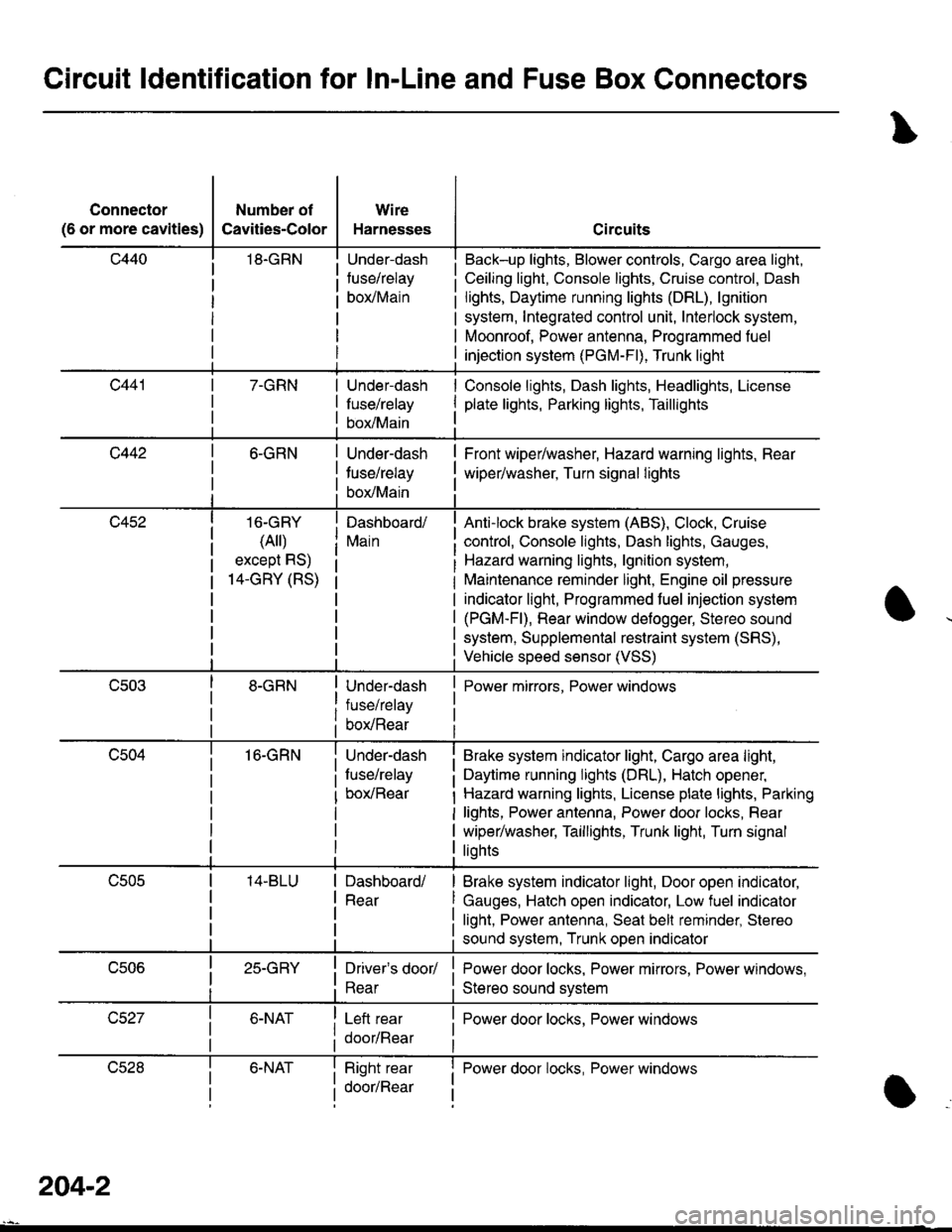
Circuit ldentification for In-Line and Fuse Box Gonnectors
Connector
(6 or more cavities)
Number of
Cavities-Color
18.GRN
Wire
Harnesses
Under-dash
fuse/relay
borMain
Circuits
Back-up lights, Blower controls, Cargo area light,
Ceiling light, Console lights, Cruise control, Dash
lights, Daytime running lights (DRL), lgnition
system, Integrated control unit, Interlock system,
Moonroof, Power antenna, Programmed fuel
injection system (PGM-Fl), Trunk light
7-GRNUnder-dash
fuse/relay
box/Main
Console lights, Dash lights, Headlights, License
plate lights, Parking lights, Taillights
c4426-GRN
16-GRY
(Ail)
except RS)
14-GRY (RS)
16-GRN
Under-dash
tuse/relay
box/Main
Dashboard/
Main
Under-dash
fuse/relay
box/Rear
Under-dash
fuse/relay
box/Rear
Front wiper/washer, Hazard warning lights, Rear
wiper/washer, Turn signal lights
Anti-lock brake system (ABS), Clock, Cruise
control, Console lights, Dash lights, Gauges,
Hazard warning lights, lgnition system,
Maintenance reminder light, Engine oil pressure
indicator light, Programmed fuel injection system
(PGM-Fl), Rear window defogger, Stereo sound
system, Supplemental restraint system (SRS),
Vehicle speed sensor (VSS)
Power mirrors, Power windows
Brake system indicator light, Cargo area light,
Daytime running lights (DRL), Hatch opener,
Hazard warning lights, License plate lights, Parking
lights, Power antenna, Power door locks, Rear
wiper/washer, Taillights, Trunk light, Turn signal
liohts
Dashboard/
Rear
Brake system indicator light, Door open indicator,
Gauges, Hatch open indicator, Low fuel indicator
light, Power antenna, Seat bell reminder, Stereo
sound system, Trunk open indicator
25-GRYDriver's door/
Rear
Left rear
door/Rear
Power door locks, Power mirrors, Power windows,
Stereo sound svstem
I Power door locks, Power windows
lJczat6-NATRight rear
door/Rear
I Power door locks, Power windowsI
a
204-2