Power windows HONDA INTEGRA 1998 4.G Workshop Manual
[x] Cancel search | Manufacturer: HONDA, Model Year: 1998, Model line: INTEGRA, Model: HONDA INTEGRA 1998 4.GPages: 1681, PDF Size: 54.22 MB
Page 833 of 1681
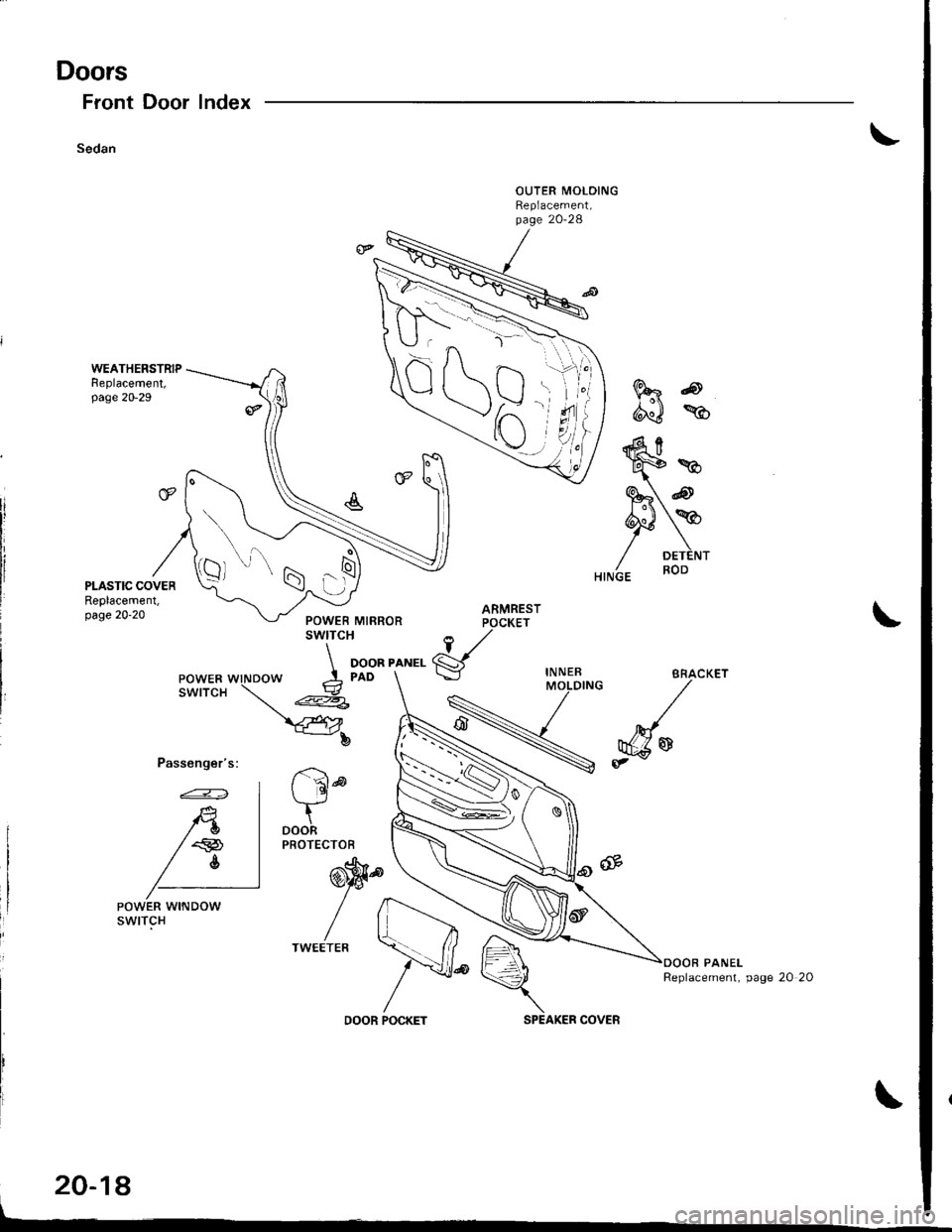
Doors
Front Door
Sedan
Index
Passenger's:
FRo
d"J %
ARMRESTPOCKET
1,/
gIN NERMOLDING
r '6ld
tDOORPROTECTOB
@'9.
//
/lTWEETEB
20-18
POWER WINDOWswtTcH
Replacement, page 20 20
DOOR POCKETSPEAKER COVER
\-^\
\
Qt
-N'a x^ l---r z
)r\
s'ti
7t"i
.1\N
J.-ra 1--
o t
:6
w*
S" @
PY/ DETENT
Page 856 of 1681
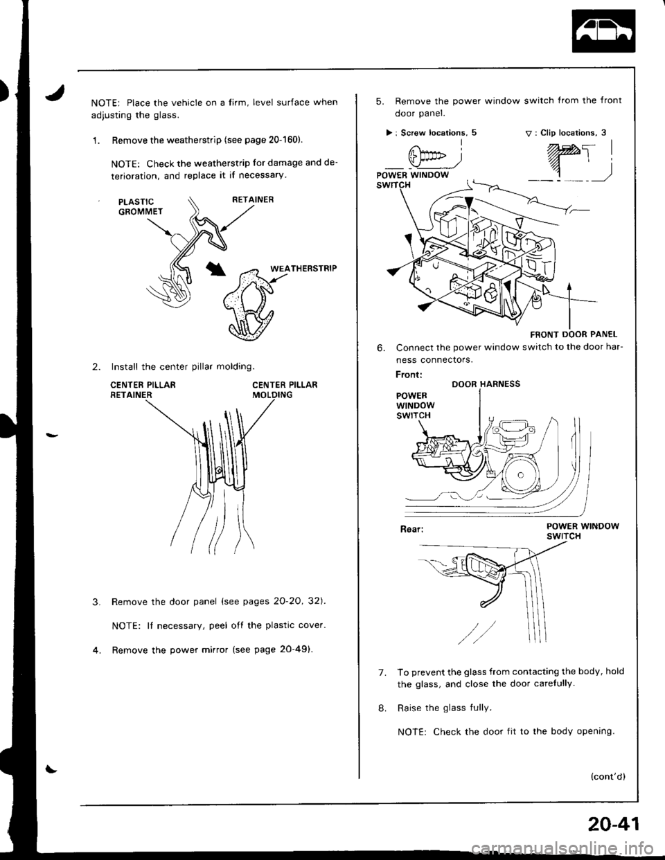
NOTE; Place the vehicle on a lirm, level surface when
adjusting the glass.
1 . Remove the weatherstrip (see page 20-1601.
NOTE: Check the weatherstrip lor damage and de-
terioration, and replace it if necessary
RETAINER
*T5FrHERsrR'P
\v
CENTER PILLAR
2. Install the center pillar molding.
CENTEF PILLARRETAINER
PLASTICGROMMET
3.Remove the door panel (see pages 2O-2O, 32]'.
NOTE: It necessary, peel off the plastic cover.
Remove the power mirror (see page 20-49).
5. Remove the power window switch from the front
ooor paner.
> i Screw locations, 5v: Clip locations, 3
FRONT DOOR PANEL
6. Connect the power window switch to the door har-
ness connectors.
Front:DOOR HARNESS
POWERWINDOWswtrcH
7.To prevent the glass from contacting the body, hold
the glass, and close the door carefully.
Raise the glass fully.
NOTE: Check the door fit to the body opening.
(cont'd)
20-41
Page 1285 of 1681
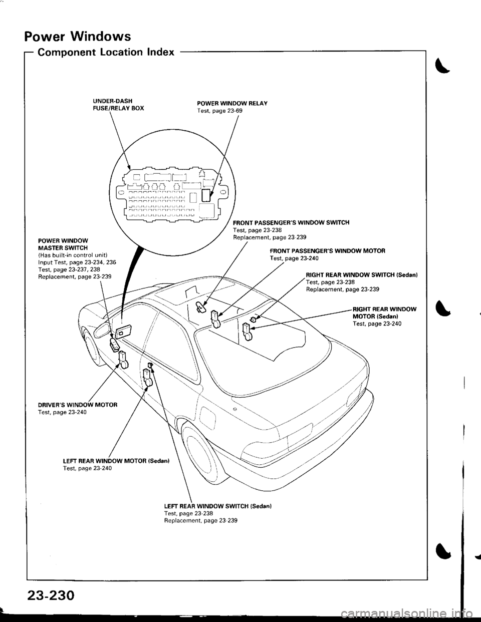
Power Windows
POWER WINDOWMASTER SWITCH(Has built-in control unitiInput Test, page 23-234, 236Iesr, page 23-23'1 ,238Replacement, page 23'239
Component Location Index
UNDER.DASHFUSE/RELAY BOX
DRIVER'STest, page 23-240
LEFT REAR WINDOW MOTOR isedan)Test, page 23 240
POWER WINDOW RELAYTest, page 23-69
LEFT REAR WINDOW SWITCH {Sedan)Test, page 23 238Replacement, page 23 239
FRONT PASSENGER'S WINDOW SWITCHTest, page 23 238Replacement, page 23 239
FRONT PASSENGER'S WINDOW MOTOFTest, page 23-240
RIGHT REAR WINDOW SWITCH (Sedanl
Test, page 23 238Replacement, page 23-239
RIGHT REAR WINOOWMOTOR lsedanlTest, page 23-240
a rrrr'---rnnrn Tl---t----, .----r- L l
(
\
23-230
Page 1287 of 1681
ir
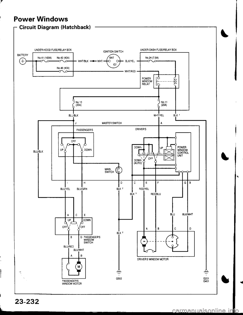
Power Windows
Circuit Diagram (Hatchback)
I'FED/BLU
DRIVER'S WINDOW MOTOR
23-232
Page 1289 of 1681
i
Power Windows
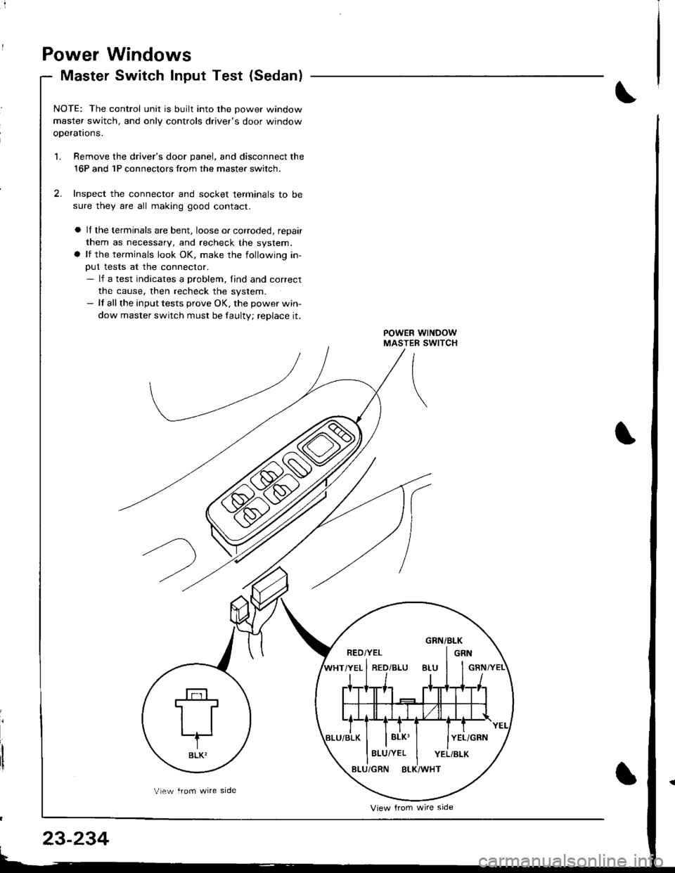
Master Switch Input Test (Sedan)
NOTE: The control unit is built into the Dower window
master switch, and only controls driver's door window
oDeratrons.
1. Bemove the driver's door panel, and disconnect the
16P and 1P connectors from the master switch.
2. Inspect the connector and socket terminals to be
sure they are all making good contact.
a ll the terminals are bent, loose or corroded, repair
them as necessary, and recheck the system.
a lf the terminals look OK, make the following in-
out tests at the conneclor.- lf a test indicates a problem, find and correct
the cause, then recheck the system.- lf all the input tests prove OK, the power win-
dow master switch must be faultV; replace it.
GRN/BLK
LT
BLK'
View trom wire side
23-234
Vlew from wire side
Page 1291 of 1681
Power
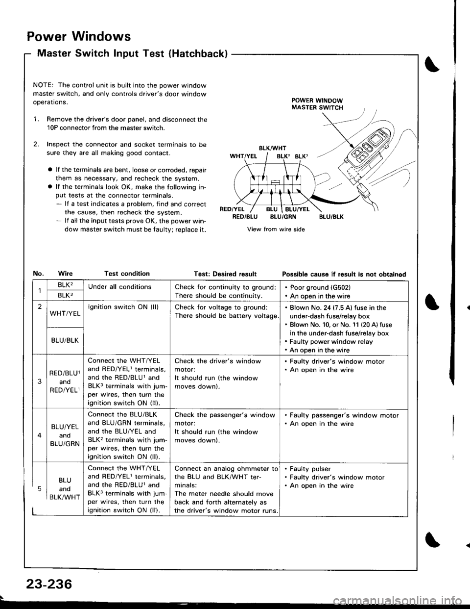
Master
Windows
Switch Input Test (Hatchbackl
NOTE: The control unit is built into the power window
master switch, and only controls driver's door window
ooerations.POWER WINDOWMASTER SWITCH
1.Remove the driver's door panel, and disconnect the
10P connectorfrom the master switcn.
Inspect the connector and socket terminals to be
sure they are all making good contact.
a lI the terminals are bent, loose or corroded, reDair
them as necessary, and recheck the system.
a lf the terminals look OK, make the following in-
put tests at the connector terminals.- It a test indicates a problem, find and correct
the cause, then recheck the system.- lf all the input tests prove OK, the power win-
dow master switch must be taulty; reDlace it.
No.WileTest condition
BLK/WHT
BLK' BLKI
RED/YELRED/BLUBLU/GRNBLU/BLK
View from wire side
Tgst: DesiredresultPossibls cause if result is not obtainsd
BLU
and
BLK/WHT
Check for continuity to ground:
There should be continuity.
Poor ground (G502)
An open in the wire
lgnition switch ON (ll)Check for voltage to ground:
There should be battery voltage
. Blown No. 24 (7.5 A) fuse in the
under-dash fuse/relay box' Blown No. 10, or No. '11 (20 A) fuse
in the under-dash fuse/relay box. Faulty power window relay. An open in the wire
Connect the WHT/YEL
and RED/YELI terminals,
and the RED/BLU1 and
BLK3 terminals with jum-
per wires, then turn the
ignition switch ON (ll).
Check the driver's window
motor:
It should run (the window
moves oownl.
. Faulty driver's window motor. An open in the wire
Connect the BLU/BLK
and BLU/GRN terminals,
and the BLU/YEL and
BLK2 terminals wjth jum-
per wires, then turn the
ignition switch ON (ll).
Check the passenger's window
motor:
It should run (the window
moves oownl.
. Faulty passenger's window motor. An open jn the wire
Connect the WHT/YEL
and RED/YEL1 terminals.
and the RED/BLUI and
BLK3 terminals with jum-
per wires, then turn the
ignition swirch ON (ll).
Connect an analog ohmmeter to
the BLU and BLK/WHT ter-
minals:
The meter needle should move
back and forth alternately as
the driver's window motor runs.
. Faulty pulser. Faulty driver's window motor. An open in the wire
23-236
Page 1293 of 1681
Power Windows
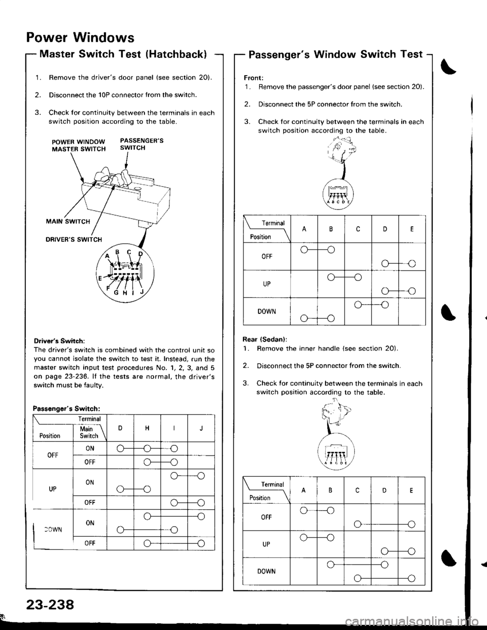
Master Switch Test (Hatchback)Passenger's Window Switch Test
Remove the driver's door panel (see section 20).
Disconnect the 10P connector trom the switch.
Check for continuity between the terminals in each
switch position according to the table.
POWERwtNDOW PASSENGER'S
MASTER SWTTCH swtTCH
Driver's Switch:
The driver's switch is combined with the control unit so
you cannot isolate the switch to test it. Instead, run the
master switch input test p.ocedures No. 1, 2, 3, and 5
on page 23-236. lf the tests are normal, the driver's
switch must be iaultv.
/+ r' \'ir=i;l,r
.JJ#iill
ryfi'\
Front:'1. Remove the passenger's door panel (see sectaon 20).
2. Disconnect the 5P connector from the switch.
3. Check for continuity between the terminals in each
switch position according to the table.
Real (Sedan):
1. Remove the inner handle (see section 20).
2. Disconnect the 5P connector from the switch.
3. Check tor continuity between the terminals in each
switch position according to the table.
Terminal
'*';__\cD
OFFo---o
o---o
UPo---o
o-
DOWN
o---o
o--'o
Terminal
t"t-* \cD
OFFo---o
o---o
UPo--_o
o---o
DOWNo---o
--oo-
Passenger's Switch:
23-238
Page 1295 of 1681
Power Windows
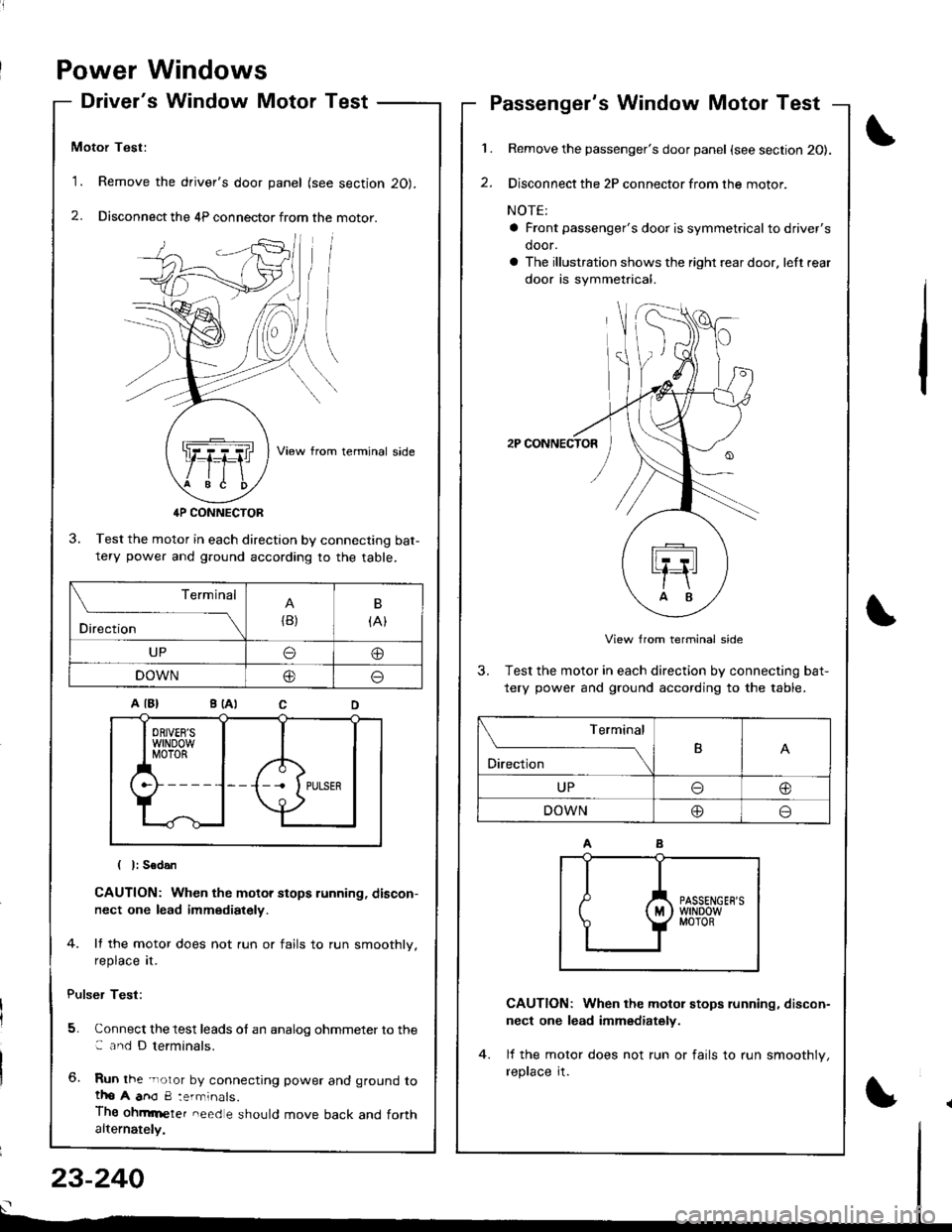
Driver's Window Motor Test
Motor Test:
'1. Remove the driver's door panel (see section 20).
2. Disconnect the 4P connector from the motor.
View from terminal side
4P CONNECTOR
3. Test the motor in each direction by connecting bat-tery power and g.ound according to the table.
CAUTION: When the motor stops running, discon-
nect one lead immediately.
4. lf the motor does not run or fails to run smoothly.
reprace rI.
Pulser Test:
5. Connect the test leads of an analog ohmmeter to the: and D terminals.
6. Run the -noror by connecting power and ground totho A anO 8:errninals.
Thg ohmrneter need e should move back and forthalternately,
1.
2.
Passenger's Window Motor Test
Remove the passenger's door panel {see section 20).
Disconnect the 2P connector from the motor.
NOTE:
a Front passenger's door is symmetricalto driver's
door.
a The illustration shows the right rear door. left rear
door is symmetrical.
2P CONNECTOR
View from terminal side
3. Test the motor in each direction by connecting bat-
tery power and ground according to the table.
CAUTION: When the motol stops running, discon-
nect one lead immediately.
lf the motor does not run or fails to run smoothlv,
reprace rI.
(
I
Terminal
Direction{B)
B
{At
UPo@
DOWN@o
Terminal
O'*"r*-TB
UPo@
DOWN@o
23-240
Page 1383 of 1681
).1
Contents
How to Use This l\.4anual 1Circuit Schematics (see Circuit Index)Fuse/Relaylnformation 6ComponentLocation Photographs 201
Connector Cavity Numbers 202Connectorldentification 203
Ground-to-Components Index 6-6Wire Harness Routing 203Circuit ldentification lor ln-Line and Fuse Box Connectors
Circuit Index
Air conditionerAir delivery 61Blower controls 60Compressor controls 62Fans 63Anti-lock brake system (ABS) 44A/T gear position indicator 89Automatic transmission controls'98199 models 39'00 models 39-4Back-up lightsHatchback 110Sedan 110- 1Brake system indicator light
USA 71Canada 71-1Brake lightsHatchback 110-6Sedan 110-7Cargo area light (Hatchback) 114-3Ceiling light 114-2Charging system 22Cigarette lighter 155
Clock 154Condenser fan 63Console lights 114Cruise control 34Dash lights 1 14Daytime running lights 110-8Door open indicator 114-2Engine coolant temperature gauge 81Engine oil pressure indicator light 72Fog lights 110-14Front parking lights 110-11Front side marker lights 110-11Fuel gauge 81Fuse/relay boxUnder-dash 6Under-hood 6-3Under-hood ABS 6-5Gauges 81Glove box light 114Ground distribution 14Ground-to-Componentsindex 6-6Hatch open indicator '114-3
Hatch opener '134
Hazard warning lightsHatchback 'l l0-2Sedan 110-4Headlights 1'10-8Headlight switch 100HeaterAir delivery 61Blower controls 60Fanswith A,/C 63without A,/C 63-2Horns 40lgnilion key reminder 73lgnition system 20
204
lmmobilizer system ('00 model) 132lndicators 80Integrated control unit 70Interlock system'98199 models 138'00 models 138-1License plate lightsHatchback 110-12Sedan 110-13Lights-on reminder 73Low fuel indicator light 74l\,4aintenance reminder light 83l\iloonroof 122Odometer 81-1Power antenna 151Power distributionBattery to ignilion switch, fuses, and relays
Fuses to relays and components 10-2Power door locksHatchback '130
Sedan 130-2Power mirrorsHatchback 141Sedan 141-1Power windowsHatchback 120Sedan 120-2Programmed fuel injection system (PGM-Fl)'98199 models 23'00 models 24Radiator fanwith tuC 63without A,/C 63-2Rear parking lightsHatchback 110-12Sedan 110- 13Rear window defogger 64Seat belt reminder 73Security system 133Speedometer Il-1Spotlights 114-2Starting syslemAutomalictransmission 21l\.4anualtransmission 21-1Stereo sound system 150Supplemental restraint system (SRS) 47Tachometer 81- 1TaillightsHatchback 110-12Sedan 110-13Trailer lighting conneclor 118Trunk lid open indicator 114-3Trunk light (Sedan) 114-3Turn signal lightsHatchback 110-2Sedan 110-4Vehicle speed sensor (VSS) 33Wiper/washerFront 91Rear 92
10
).1
I
Xr
12Fg oAmerican Honda Motor Co., Inc. - All Rights Reserved Service Communications 275 pages
Page 1415 of 1681
HOODI I a FUSE/
FUsE 43 I ruse +e I ruse ao I lFliYr{rEFroi S;,;; .' S "o"*-- laoxLlcrrr .( i!i,- / i,vr-,iiroirv lpHara2lLrGtfT a rsA a LlI7,5AttM
6lr----- -T---=(?:;t",'
""'"'.I!E-
- i i
t-----------1----ll[qi:".1*
| I
! "-J-E'11,.o"o,,o
LljF*ff: ] lj
-';[""..."'-'l
--'""'"f
t*""
f
n%-
'--l I
*","."|-i
.==.i '5l5j*,,,
I
,^lJr^r '
$ rx: - f ,*t,*""o"""",",, ;#,ii3J'"
"'
tcoNNEcroR ,n",".o
!
*","."!il""!,l""lroio'"*"'
I:18;?'alJ)"")
,
'::t:::-.
[, [
|
im-*,1,*,
::It*"xt*"'
***tr-i
""**
*HTFEDI ! i I
tl
i-"'"."1
i 'n*'"'ol -"'"."N
,1.,,, I i i"-""{
ffirT"-',-'lii : ll lfr-i
i-"'"."1
i 'n*'"."[ ","'"."[
[ I li#""i
i ,I*., i
'*""'*',{=.,
,'I=rTt':.
',;,["ff;,,-
i h*r*
iwnrneo l ' wHrREol wHrFEDl I I I !'i;-""t'l: ! : [ [ ll ! l r*"--l
: I : .. .^ I I *",n..
a a : a ai ti | ''-'----' a3l?3"1?.
| | : I I | | I I a PHoro^o I!--J ; !--J L--J L--J L-----J
SpOTLtcHTS ' CEIL1NG TRUNK/ pOWER UNDER-DASH
eaoe lti-z I LtcHT CARGO ANTENNA FUSE/RELAY Box', eige tt+-z AREA MoToR . PHoro 58faQe 114-2 AIIEA M(J |
rltl'cii Floil'sr -
, Page 114-3 pHoro 1as To Fuses 7, 8, iO, and 1.|,' With i tor dotails se€ Power Windows,'-- i/loonroof --' pagel2}o( 120-2.
(cont'd)
10-7