Transmission HONDA INTEGRA 1998 4.G User Guide
[x] Cancel search | Manufacturer: HONDA, Model Year: 1998, Model line: INTEGRA, Model: HONDA INTEGRA 1998 4.GPages: 1681, PDF Size: 54.22 MB
Page 311 of 1681
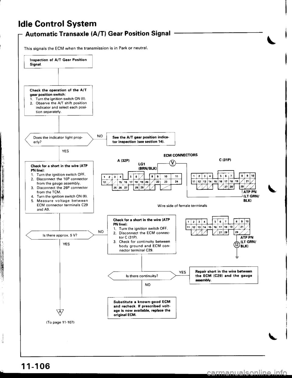
ldle Control System
Check lor a 3hon in the wiro IATPPN linel:1. Turn the ignition switch OFF.2. Disconnect the 10P connectorfrom the gauge assembly.3. Disconnect the 26P connectorfrom the TCM.4. Turn the ignition switch ON (ll).
5. Mea su re voltage betweenECM connector terminals C29and A9.
Automatic Transaxle {A/T) Gear Position Signal
1 1-106r.
This signals the ECM when the transmission is in Park or neutral.
(To page 11-107)
Check the oparation ot the A/Tg6ar posilion switch:1. Turn the ignition switch ON (ll).
2. observe the A/T shitt position
indicator and select each Posi'tion separately.
560 the A/T go.r position indice-tor inroection lseo section 141.
Check tor r 3hort in tho wiro (ATP
PN lino):1. Iurn the ignition switch OFF.2. Disconnect the ECM connec-tor C (31P).
3. Check for continuity betweenbody ground and ECM con'nector terminal C29.
ls there approx.5 V?
Rcpair short in the wir6 batwoentho ECM lc29l and the gauge
6er$lv.
Substitute a known-90od ECMand rccheck. lf prescribed volt-ago is now avail.ble, rcplacc thooriginal ECM.
,PN
GRN/
LGIIBRN/BLKI
ATP PN
ILT GRN/BLKI
Wire side of temale terminals
12355It0
11 1213t319
2A29/,a
I ArP
d llr (
Il/BLKI
Page 312 of 1681
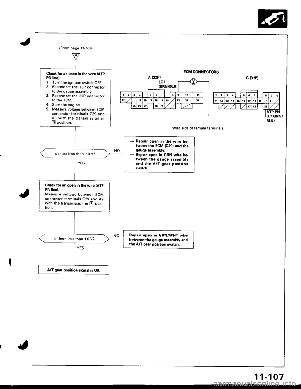
{From page 11-'106)
Check tor an op€n in the wiro {ATpPN lin€):Turn the ignition switch OFF.Fgconnect the 10P connectorto the gauge assembly.Reconnect the 26P connectorto the TCM.stan the engine.M€asure voltage between ECMconnector termanals C29 andAg with the transmission inE position.
- Ropair open in th6 wiro bo-twoen tho ECM {C291 and thogru96 a3sgmbly.- Repair open in GRN wir. bo-twaan thc gauga !srembly.nd tho A/T g.ar po3itiongwitch.
ls there less than 1.0 V?
Chod( for an opon in tho wir6 (ATPPN linel:Measure voltage between ECMconnector terminals C29 and A9with the transmission in E] posi,tron.
R.psir op.n in GRN/WHT wirob€twcan th. gaugc rsr.mbly andthc A/T ge.r po.ition 3whch.
ls there less than 1.0 V?
A/T g6er position signal i3 OK.
a l32P)LGl{BRN/BLKI
Wire side of female terminals
ATP PN{I-T GRN/BLKI
11-107
Page 330 of 1681
I
tr,
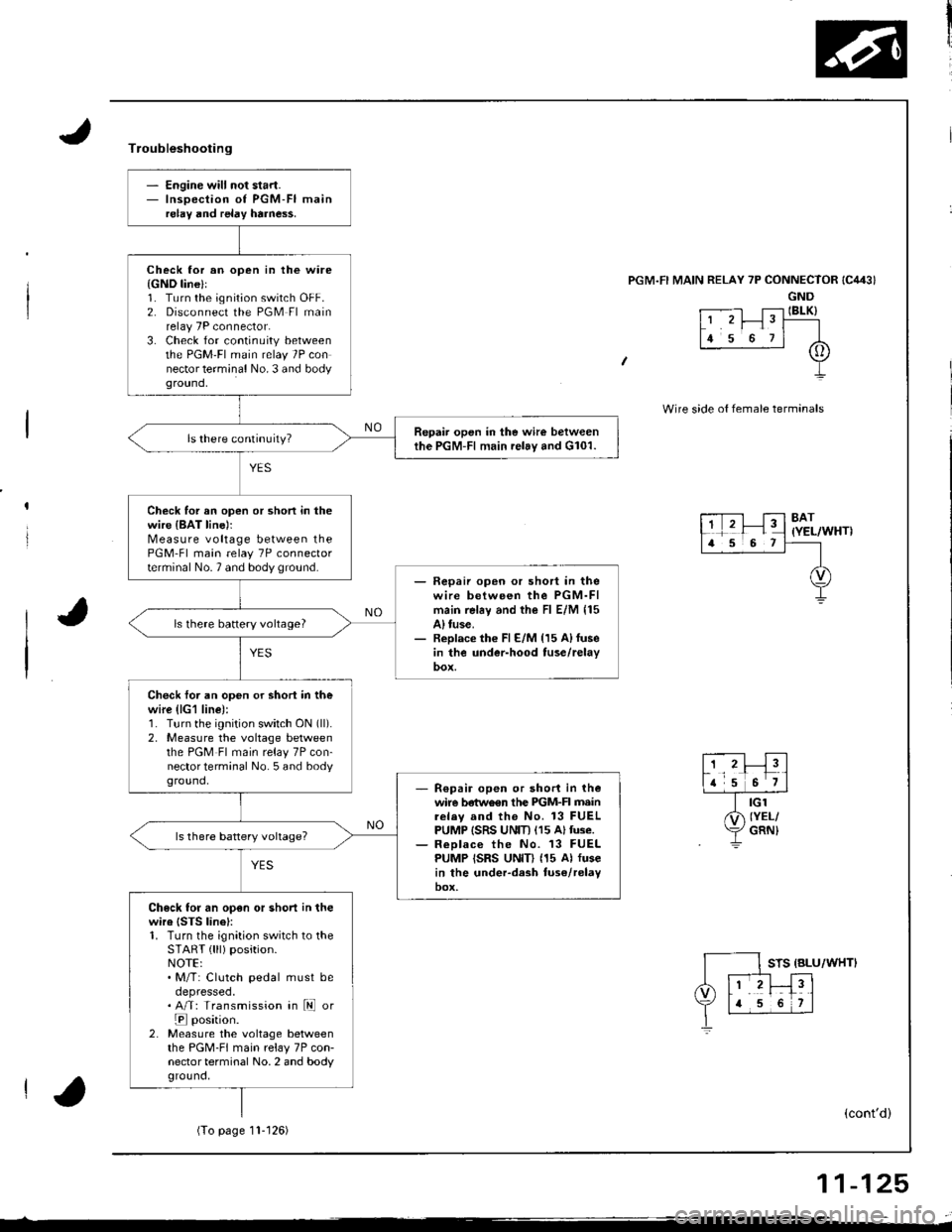
- Engine will not start.- Inspection of PGM-FI mainrelay and relay harne$.
Check lor an open in the ware{GND line}l1. Turn the ignition switch OFF.2. Disconnect the PGM Fl mainrelay 7P connector.3. Check for continuity betweenthe PGM'FI main relay 7P connector terminal No. 3 and bodyground,
Repair open in the wire betweenthe PGM-Fl main relay and G101.
Check for an open or shon in thewire {BAT line)rMeasure voltage between thePGM-Fl main relay 7P connectorterminal No.7 and body ground.- Fepaii open or short in thewire between the PGM-FImain rel6y and the Fl E/M 115A) tuse.- Replace th€ Fl E/M {15 A)fusein the under-hood tuse/relay
ls there battery vohage?
Check foi an open or shori in thewire (lG1 line):1. Turn the ignition switch ON (ll).
2, Measure the voltage betweenthe PGM Fl main relay 7P con-nector terminal No. 5 and bodyground,R€pair open or short in thewire betwo€n the PIGM-FI mainrelav and the No. 13 FUELPUMP ISRS UNIT) (15 Altuse.ReDlace the No. 13 FUELPUMP ISRS UNID (15 Al fusein the under-dash tuse/relayoox,
Check for an open or short in thewire {STS linel:1. Turn the ignition switch to theSTART { lll) position.NOTE:. M/T: Clutch pedal must beoepresseo.. A/T: Transmission in ld or
E position.2. Measure the voltage betweenthe PGM-FI main relay 7P con-nector terminal No. 2 and bodyground,
Troubleshooting
'l RELAY 7P CONNECTOR
GND
t .--.-l T;-l IBLK)L' 'r I" T----
lr s o rl A
+
Wire side o{ female termanals
8AT(YEL/WHT)
STS {BLU/WHTI
(cont'd)
(To page11- t 26)
11-125
Page 353 of 1681
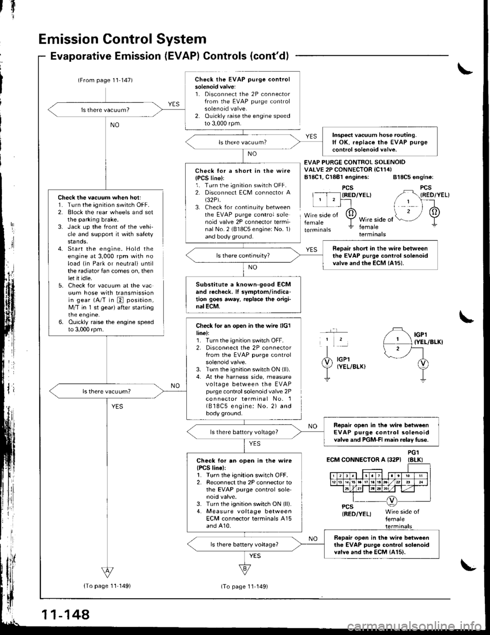
Emission Control System
Check the vacuum when hot:1. Turn the ignition switch OFF.2. Block the rear wheels and setthe parking brake.3. Jack up the front of the vehi-cle and support it with safetystands.4- Start the engine. Hold theengine at 3,000 rpm with noload (in Park or neutral) untilthe radiator fan comes on, thenlet it idle.5. Check for vacuum at the vacuum hose with transmissionin gear (A/T in E position,M/T in 'l st gear) after startingrne engrne.6. Ouickly raise the engine speedto 3,000 rpm.
Evaporative Emission (EVAP) Controls (cont'd)
(From page 1'l 147)Check the EVAP purge controlsolenoid valve:1. Disconnect the 2P connectorfrom the EVAP purge controlsolenoid valve.2. Ouickly raise the engine speedto 3,000 rpm.
{To page 11 149)
tfl'I
Check lor a short in the wire{PCS line}l1. Turn the ignition switch OFF.2. Disconnect ECM connector A(32P).
3. Check for continuity betweenthe EVAP purge control solenoid valve 2P connector termi-nal No. 2 (818C5 engine: No. 1)and body ground.
Check for an open in the wire llclline):1. Turn the ignition switch OFF.2, Disconnect the 2P connectorfrom the EVAP purge controlsolenoid valve.3. Turn the ignition switch ON (ll).
4. At the harness side, measurevo ltage between the EVAPpurge controlsolenoid valve 2Pco n nector terminal No. 1( B 18C5 engine: No. 2) andbody ground.
EVAP PURGE CONTROI SOLENOIDVALVE 2P CONNECTOR IC114)B18C1, Cl8Bl engines: 818C5 engine:
PCSIRED/YEL}
femaleWire side offemaleterminals
YES
IGPl{YEL/BLKI
IGPlIYEL/BLKI
ECM CONNECTOR A {32PIPG1IBLKI
Insp€ct vacuum hose routing.lf OK, replace the EVAP purge
control solenoid valve.
neDair short in the wire betweenthe EVAP purge control solenoidvalve and the ECM lAl5).
Substitute a known-90od ECMand recheck. lI symptom/indica-tion goes away, replace the origi-nal ECM.
Repair open in the wirc betweenEVAP purge control solenoidvalve and PGM-FI main relav fuse.ls there battery voltage?
Check for an open in the wireIPCS linel:1. Turn the ignition switch OFF.2. Reconnect the 2P connector tothe EVAP purge control sole'noid valve.3. Turn the ignition switch ON (ll).
4. Measure voltage betweenECM connector terminals A15and A10.
Bopair open in the wiro betweenthe EVAP purgo control 3olanoidvalvo and the EcM {415).
11-144
(To page 11-149)
Page 357 of 1681
Transaxle
Clutch ...........12-1
Manual Transmission ............................ 13-1
Automatic Transmission ....................... 1 4-1
Differential
Manual Transmission
B1881 engine ................................... 15-1
818C1 engine ................................... 15-9
B18C5 engine .............. 15-19
Automatic Transmission ................. .. 15-27
Driveshafts ... 16-1
Page 360 of 1681
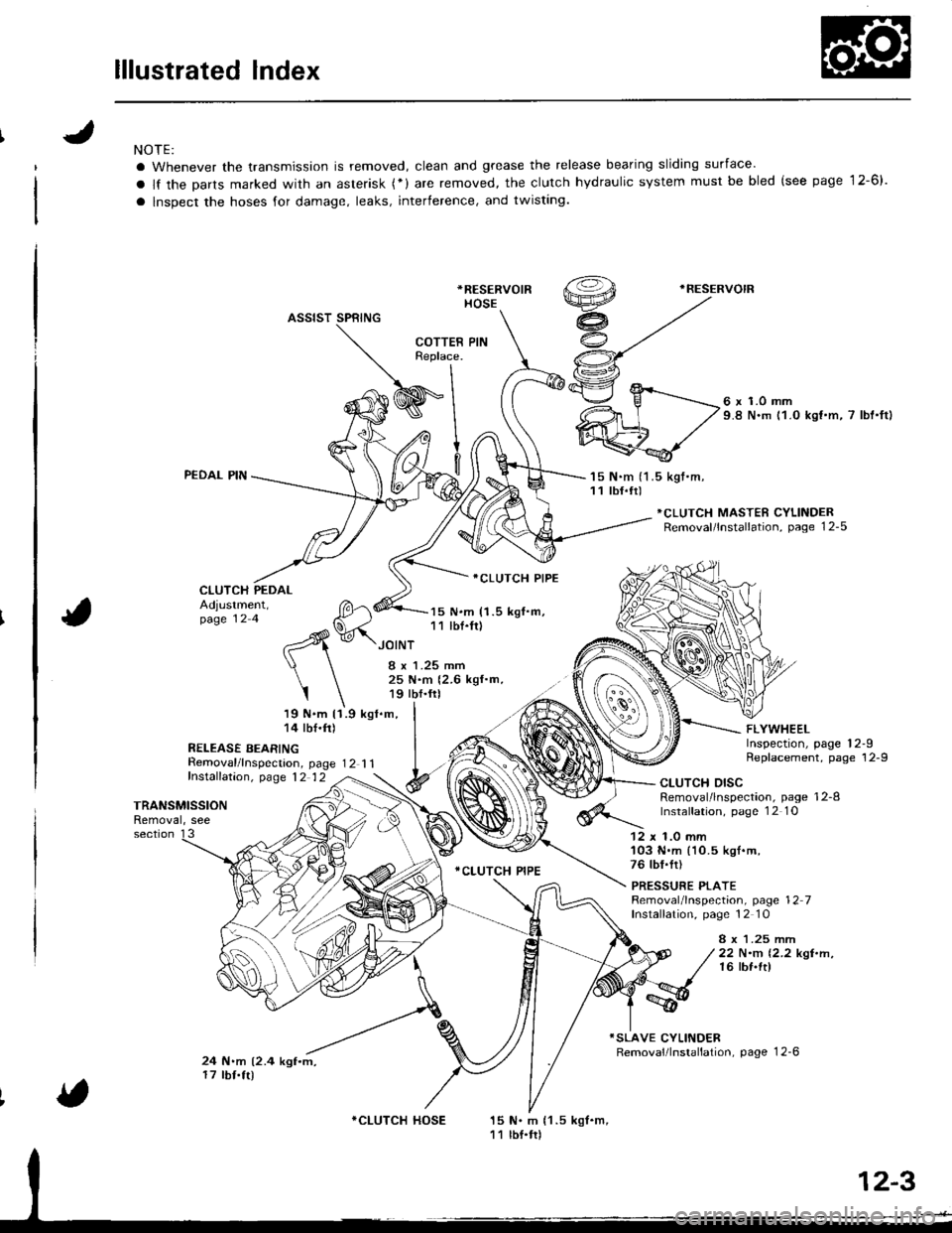
lllustrated Index
NOTE:
a Whenever the transmission is removed, clean and grease the release bearing sliding surface'
a lf the Darts marked with an asterisk (*) are removed, the clutch hydraulic system must be bled (see page 12-6).
a lnspect the hoses for damage, leaks, interference, and twisting.
*RESERVOIR
HOSE
.RESERVOIR
ASSIST SPRING
PEDAL PIN
CLUTCH PEDAL
Removal/lnspecrion, page 12 1 1fnstalfation, p,age 12 12
6 x 1.0 mm9.8 N.m 11.0 kst.m, 7 lbt'ftl
'15 N.m (1 .5 kgt.m,11 tbf.tr)
*CLUTCH MASTER CYLINDERRemoval/lnstallation, page 12-5
Adjustment,page 12 4
19 N.m 11.9 kgl.m,14 tbf.ft)
R€LEASE BEARING
15 N.m (1.5 kgf.m,11 lbf.fr)
ICLUTCH PIPE
.CLUTCH PIPE
FLYWHEELInspection, page 12-9Replacement, page 12-9
JOINT
I x 1.25 mm25 N.m {2.6 kgf.m,19 tbf.frl
I
TRANSMISSIONRemoval, see
CLUTCH DISCRemoval/lnspection, page 12-8lnstalfation, page 1 2 1O
section 1312 x 1.0 mm'103 N.m (10.5 kgl.m,76 tbf.fr)
PRESSURE PLATERemoval/lnspection, page 12 7Installation, page 12 10
8 x 1.25 mrr|22 N.m 12.2 kgt.n,16 lbf.ft)
24 N.m (2.4 kgf.m,17 tbf.tr)
15 N. m {1 .5 kgf.m,11 lbf.tr)
COTTERReplace.
I
WInl
9l
v.^- fl
*CLUTCH HOSE
Page 370 of 1681
Manual Transmission
Special Tools ............. 13-2
Maintenance
Transmission Oil .............................. 13-3
Back-up Light Switch
Replacement ......... 13-3
Transmission Assembly
Removal ................. 13-4
lllustrated Index ................................... 13-8
Transmission Housing
Removal ................. 13-10
Peverse Change Holder, Reverse ldler Gear
jGlearance Inspection ....................... 13-1 1
Removal ................. 13-12
Change Holder Assembly
Clearance Inspection .....,.,....,,.....,,.. 13-13
Removal ................. 13-15
Disassembly/Reassembly ............... 13-16
Mainshaft, Countershaft, Shift Fork
Removal ................. 13-17
Shift Rod
Removal ................. 13-18
Shift Fork Assembly
Index ................ ...... 13-19
Clearance lnspection ...................,.,. 13-20
Mainshaft Assembly
fndex ................ ......13-21
Clearance f nspection ..,,,.................. 13-22
Disassembly .......... 13-25
Inspection .............. 13-26
Reassembly ........... 13-21
Countershaft Assembly
Index ................ ...... 13-28
Clearance Inspection ....................... 13-29
Disassembly .......... 13-30
Inspestion .............. 13-31
Reassembly ........... 13-32
Synchro Sleeve, Synchro Hub
Inspection .............. 13-34
Installation ............. 13-34
Synchro Ring, Gear
Inspection .............. 13-35
Clutch Housing Bearing
Replacement ......... 13-36
Mainshaft Thrust Clearance
Adiustment ............ 13-38
Transmission
Reassembly ........... 13-41
Transmission Assembly
Installation ............. 13-46
Gearshift Mechanism
Overhaul ................ 13-51
Page 372 of 1681
aintenance
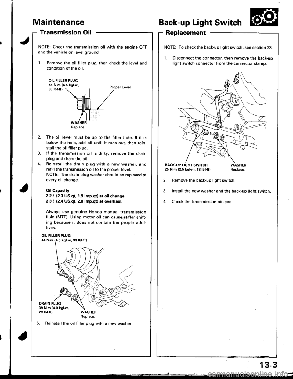
Transmission Oil
NOTE: Check the transmission oil with the engine OFF
and the vehicle on level ground.
1. Remove the oil filler plug, then check the level and
condition of the oil.
OIL FILLER PLUG44 N.m {4.5 kgf.m,Proper Level33 tbf.ftl
The oil level must be up to the filler hole. lf it is
below the hole, add oil until it runs out, then rein-
stall the oil filler plug.
lf the transmission oil is dirty, remove the drainplug and drain the oil.
Reinstall the drain plug with a new washer, and
refillthe transmission oilto the proper tevet.
NOTE: The drain plug washer should be replaced at
every oil change.
Oil Capacity
2.2 | i.2.3 US.qr,1.9 lmp.qtl at oil ch.nge.
2.3 t l2.1US.qt,2.O lmp.qtl at ovorhaul.
Always use genuine Honda manual transmission
fluid (MTF). Using motor oil can causa€tiffer shift-
ing because it does not contain the proper addi-
Back-up Light Switch
Replacement
NOTE: To check the back-up light switch. see section 23.
1. Disconnect the connector, then remove the back-up
light switch connector from the connector clamp.
l.m {2.5 kgf.m, 18lbf.ft) Replace.
Remove the back-up light switch.
Install the new washer and the back-up light switch.
Check the transmission oil level.
!ves.
OIL FILLER PLUG
DRAIN PLUG39 N.m {4.0 kg{.m,29 rbf.ftlReplace.
5. Reinstall the oil filler plug with a new washer,
Replace.
EACK.UP LIGHT SWITCH25 N.m {2.5 kgf.m, 18 lbf.ft)
13.3
Page 373 of 1681
Transmission Assembly
Removal
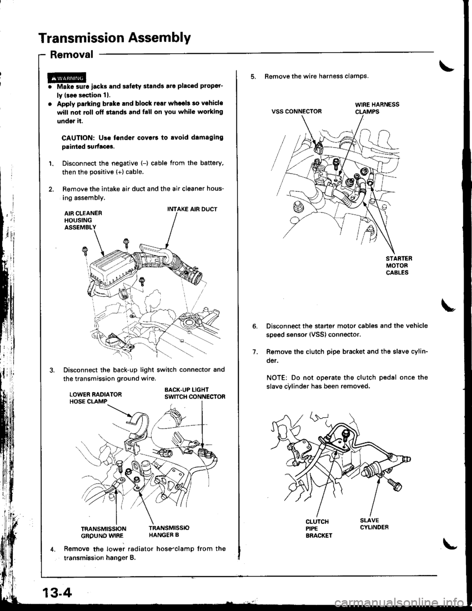
r@i Make surs iacks and safety stands sro placod propor-
ly (3ee s€ction 1).
. Apply parking brake and block resr whaeb 30 vohicle
will not roll off stands and hll on You whil6 working
under it.
CAUTION: Use fender covers to svoid damaging
paintod surtacos.
1. Disconnect the negative (-) cable from the battery,
then the positive {+) cable.
2. Remove the intake 8ir duct and the air cleaner hous-
ing assembly,
AIR CLEANERHOUSINGASSEMBL
Disconnect the back-up light switch connector and
the transmission ground wire.
BACK.UP LIGHTSWITCH CONNECTOR
TRANSMISSIONTRANSMISSIO
GROUND WIRE HANGEB B
4. Remove tne lowei radiator hose"clamp from the
transmission hsnger B.
INTAKE AIR DUCT
13-4
\-
5. Remove the wire hsrness clamps.
VSS CONNECTOR
Disconnect the starter motor cables and the vehicle
speed sensor (VSS) connector.
Remove the clutch pipe bracket and the slave cylin-
der.
NOT€: Do not operate the clutch pedsl once the
slave cvlinder has been removed.
7.
Page 374 of 1681
I
T
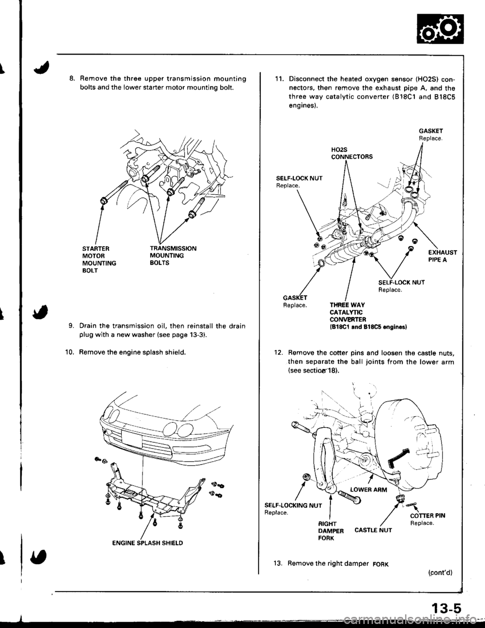
Remove the three upper transmission mounting
bolts and the lower starter motor mountino bolt.
STARTERMOTOEMOUNTINGBOLT
Drain the transmission oil, then reinstall the drainplug with a new washer (see page 13-3).
Remove the engine splash shield.10.
11.
6tr!
/
SELF.LOC1(ING NUTReplace.
Disconnect the heated oxygen sensor (HO2S) con-
nectors, then remove the exhaust pipe A. and the
three way catalytic converter (B'18C1 and B18C5
engines).
Feplace. THREE WAYCATALYNCCONVERTENlg18C1 lnd 818C5 onginrsl
Remove the cotter pins and loosen the castle nuts,
then separate the ball joints from the lower arm(see sectiotr'l8).
LOWER ARM
DAMPER CASTLE NUTFORK
13. Remove the right damper FORK
(cont'd)
13-5